HAL Id: tel-02954030
https://tel.archives-ouvertes.fr/tel-02954030
Submitted on 30 Sep 2020HAL is a multi-disciplinary open access archive for the deposit and dissemination of sci-entific research documents, whether they are pub-lished or not. The documents may come from teaching and research institutions in France or abroad, or from public or private research centers.
L’archive ouverte pluridisciplinaire HAL, est destinée au dépôt et à la diffusion de documents scientifiques de niveau recherche, publiés ou non, émanant des établissements d’enseignement et de recherche français ou étrangers, des laboratoires publics ou privés.
Modeling and Robust Control of Cable-Driven Parallel
Robots for Industrial Applications
Etienne Picard
To cite this version:
Etienne Picard. Modeling and Robust Control of Cable-Driven Parallel Robots for Industrial Appli-cations. Automatic. École centrale de Nantes, 2019. English. �NNT : 2019ECDN0067�. �tel-02954030�
T
HESE DE DOCTORAT DE
L'ÉCOLE
CENTRALE
DE
NANTES
COMUE UNIVERSITE BRETAGNE LOIRE
ECOLE DOCTORALE N°602
Sciences pour l'Ingénieur
Spécialité : Robotique – Mécanique
Modeling and Robust Control of Cable-Driven Parallel Robots
for Industrial Applications
Thèse présentée et soutenue à Bouguenais, le 17/12/2019
Unité de recherche : UMR 6004, Laboratoire des Sciences du Numérique de Nantes (LS2N)
Par
Etienne PICARD
Rapporteurs avant soutenance :
Edouard Laroche Professeur des Universités, ICUBE - Université de Strasbourg David Daney Senior Inria Researcher, Inria
Composition du Jury :
Président : Marco Carricato Associate Professor, Università di Bologna Examinateur : Claire Dumas Chargée de projets - Experte robotique, DAHER
Rapporteurs : Edouard Laroche Professeur des Universités, ICUBE - Université de Strasbourg David Daney Senior Inria Researcher, Inria
Dir. de thèse : Stéphane Caro Directeur de recherche CNRS, Centrale Nantes Co-dir. : Franck Plestan Professeur, Centrale Nantes
Co-encadrant : Fabien Claveau Enseignant-Chercheur
Modeling and Robust Control of Cable-Driven
Parallel Robots for Industrial Applications
ROCKET project
Etienne Picard
Contents
General introduction
1
Context
. . . 171.1 Cable-driven parallel robots 17
1.1.1 Workspace . . . 20 1.1.2 CDPR configuration . . . 20 1.1.3 Existing CDPRs . . . 22
1.2 ROCKET project 24
1.2.1 First application: metal plate handling . . . 26 1.2.2 Second application: window cleaning . . . 27
1.3 CDPR prototypes at IRT Jules Verne 28
1.3.1 ROMP prototype . . . 28 1.3.2 ROWC prototype . . . 32
1.4 Experimental setups 37
1.4.1 ROMP test trajectory . . . 37 1.4.2 ROWC Test trajectory . . . 37 1.4.3 Measurements . . . 39
1.5 Thesis objectives 43
1.6 Plan 44
1.7 Plan (Français) 45
I
Part I: Modeling and Calibration
2
Modeling
. . . 552.1 Geometrico-static modeling 55 2.1.1 Basic inverse geometric model (IGM I) . . . 56
2.1.2 Static equilibrium . . . 57
2.1.3 Inverse geometric model including the pulleys geometry (IGM II) . . . 57
2.2 Inverse Kinematic Model (IKM) 61 2.3 Dynamic Model 61 2.4 Cable modeling 62 2.4.1 ROMP and ROWC cables . . . 63
2.4.2 Linear cable elasticity model . . . 65
2.5 Forward kinematics of CDPRs 65 2.6 CDPR Elasto-static model 67 2.7 Payload mass and center of mass estimation 71 2.7.1 Hypotheses and equations . . . 71
2.7.2 Experimental results on ROMP . . . 73
2.8 Conclusion 81
3
Calibration
. . . 833.1 State of the art 84 3.2 Manual calibration 85 3.3 Self-calibration 86 3.3.1 Principle . . . 87
3.3.2 Problem formulation from model M1 . . . 87
3.3.3 Problem formulation from model M2 . . . 90
3.3.4 Problem formulation from model M3 . . . 91
3.3.5 Simulation results . . . 91
3.4 Conclusion 99
Part I: Conclusion
. . . 103II
Part II: Robust Control
Part II: Introduction
. . . 1074
Control
. . . 1134.1 Control design 114 4.1.1 System input and outputs . . . 114
4.1.2 Architecture choices . . . 115
4.2 CDPR position control 116 4.2.1 PC1: Basic architecture . . . 116
4.2.2 PC2: Control with feedforward . . . 117
4.2.3 PC3: Control with feedforward using real time mass estimation . . . 118
4.3 CDPR control with tension distribution 120
4.3.1 Control architectures . . . 121
4.3.2 Common tension distribution algorithms . . . 122
4.3.3 Stiffness oriented tension distribution . . . 125
4.4 Controllers 128 4.4.1 Proportional-derivative controller . . . 129
4.4.2 Balancing sliding mode/linear controller . . . 130
4.5 Position control experiments (ROMP) 135 4.5.1 PC1 control architecture joint space results . . . 135
4.5.2 PC2 control architecture joint space results . . . 141
4.5.3 PC3 control architecture joint space results . . . 145
4.5.4 PC1 to PC3 control architectures Cartesian errors . . . 147
4.5.5 Evolution of parameter α in SML based controllers . . . 154
4.5.6 PCE control architecture results . . . 157
4.6 SOTDA simulation results 159 4.6.1 Static pose . . . 160
4.6.2 Along path . . . 160
4.7 SOTDA experiments (ROWC) 163 4.7.1 Static pose . . . 164
4.7.2 Along path . . . 165
4.8 Conclusion 169
5
Emergency stop
. . . 1715.1 Recovery after cable failures 171 5.2 CDPR emergency stops 173 5.2.1 Immediate top and controlled deceleration . . . 174
5.2.2 CDPR emergency stop . . . 174
5.3 Constant jerk deceleration of a suspended CDPR 176 5.3.1 Experimental setup . . . 176
5.3.2 Results . . . 177
5.4 SOTDA and overwhelming force 181 5.5 Conclusion 182
Part II: Conclusion
. . . 182Perspectives
Bibliography
Appendix
A
HTC VIVE system
. . . 207A.1 Hardware 207 A.1.1 Software . . . 209
A.2 Tracking performances 209
B
Friction identification on CAROCA prototype
. . . 211C
SML behavior in TC2 architecture
. . . 215D
SOTDA: grid versus corner
. . . 219List of Figures
1.1 Serial and parallel mechanisms. . . 18
1.2 Gough-Stewart platform 3D model (left) and the AMiBA telescope (right). . . 18
1.3 CDPR used for sandblasting and painting operations [GGC18]. . . 19
1.4 Two Cable-Driven Parallel Robot configurations. . . 21
1.5 Skycam in a football stadium in the USA. . . 23
1.6 Fraunhofer CableRobot Simulator. . . 23
1.7 CDPR used as haptic interfaces. . . 24
1.8 Haption INCA 6D at ICube laboratory [CCL17]. . . 25
1.9 The COGIRO prototype developed at LIRMM [Gou+15]. . . 25
1.10 Metal plates with of different shapes and masses. . . 26
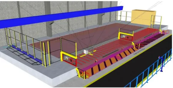
1.11 Possible CDPR implementation for metal parts handling in an industrial environment. . . 26
1.12 ROCKET Human Machine Interface (HMI) with augmented reality. A camera installed on the platform shows the magnets status while the operator controls the platform motion with joysticks. . . 27
1.13 Left. Side view of a cruise ship, which requires regular rinsing of the outer shell and windows. Right. Current solution on rails. . . 28
1.14 CAROCA cell at IRT Jules Verne (Technocampus Ocean). . . 29
1.15 ROMP prototype Top. The moving-platform (MP) equipped with five magnets to pick metal parts and eight dynamometers to measure cable tensions. Bottom. A motor, a winch and a pulley. . . 30
1.16 Close-up view of Left. A Magswitch® magnet under ROMP platform Right. A Tractel® force sensor located between a cable and an anchor point. . . 30
1.17 ROMP prototype static workspace for tmax= 2667 N. . . 32
1.18 ROMP software architecture. . . 33
1.19 ROMP software and hardware interactions. . . 34
1.21 ROWC platform CAD model with retracted and deployed end-effector. 35
1.22 ROWC prototype wrench feasible workspace. . . 36
1.23 Top and side views of ROMP test trajectory. . . 37
1.24 ROMP test trajectory in blue and CDPR prototype configuration with pulleys in orange. . . 38
1.25 ROMP test trajectory desired position, speed and acceleration. . 38
1.26 Trajectory for window cleaning. . . 39
1.27 Simulated ROWC model, with trajectory portion (cyan) and external wrench due to water pressure (magenta). . . 40
1.28 Desired pose along y axis for ROWC test trajectory. . . 40
1.29 VIVE principle between a base station and a tracker. . . 41
1.30 Reference frames involved in the platform (orange) tracking relatively to the frame (blue) using two VIVE trackers (grey circles) and a base station (grey square). . . 42
1.31 The two trackers and a base station. . . 42
2.1 Direct and inverse geometric models input/output. . . 56
2.2 CDPR geometric parametrization. . . 56
2.3 ROMP pulley of diameter 150 mm. . . 58
2.4 ROWC upper (left) and lower (right) pulleys of diameter 20 mm. . 59
2.5 Top and side views of a two-DoF pulley. . . 59
2.6 Usual cable modelings. . . 64
2.7 The two prototypes cables with straight lines overlaid for comparison Left. ROMP cables Right. ROWC cables. . . 64
2.8 Metal plates M1(122 kg) and M2(249 kg). . . 73
2.9 Estimated mass (kg) with the two models defined in Sec. III.A and III.B and for the three payloads along the test trajectory; the cable tensions are measured with force sensors. . . 74
2.10 Comparison between estimated mass along ROMP test trajectory with Models I and II for the three payloads Left.Mean of mass estimation Right. Mean of mass estimation error. . . 75
2.11 Center of mass position estimation in frame Fpfor the heaviest pay-load MP+M2(615 kg) along the test trajectory with Models I and II (Top). along x-axis (Bottom). along y-axis. . . . 75
2.12 Moving platform (MP) displacing payload M2. There is an offset be-tween the center of mass of M2and axis zpalong axis xp. . . 76
2.13 Cable tension 1 (N) with force sensors measurements, raw motor torque and torque minus frictions, for the heaviest payload MP+M2(615 kg) along the test trajectory. . . 77
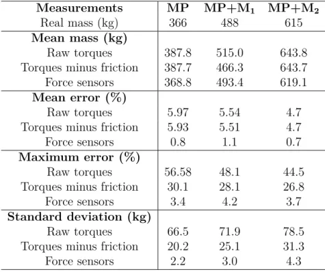
2.14 Estimated mass (kg) along the trajectory from force sensors measures, raw motor torques and motors torques minus friction model, for the heaviest payload MP+M2(615 kg). . . 78
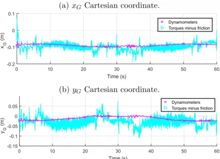
2.15 Center of mass position estimation in frame Fpfor the heaviest pay-load MP+M2(615 kg) along the test trajectory from force sensor measure-ments and motor torques minus frictions (Top). along x-axis (Bottom). along y-axis. . . 79
2.16 MP with 15 degrees rotation about y-axis. . . 79
2.17 Estimated mass (kg) of MP during orientations. . . 80
2.18 Starting with payload MP+M2, estimated mass (kg) during a sudden drop of M2. . . 80
3.1 ROMP calibration support. . . 86
3.2 Errors introduced between perfect model and initial solution. DAis the coordinate difference between A and A0, and DX the pose difference between X and X0. . . 94
3.3 3D view of of the 30 platform center poses represented by the frames, perfect Aipoints as magenta asterisks and solution A∗i as blue circles. . 95
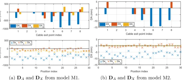
3.4 DA, DX and DL obtained with self-calibration based on model M1, from input generated from model M1. . . 96
3.5 DAand DX obtained with self-calibration based on models M1 and M2, from input generated with model M2. . . 97
3.6 DLobtained with self-calibration based on models M1 and M2, from input generated with model M2. . . 97
3.7 Results with generation from M3 and self-calibration based on model M1, M2 and M3. . . 100
4.1 System input, outputs and perturbations. . . 114
4.2 PC1 control architecture. . . 117
4.3 PC2 control architecture with feedforward terms. . . 117
4.4 PC3 ontrol architecture real-time mass compensation. . . 119
4.5 Position controller with cable elasticity compensation (PCE) . . . . 120
4.6 Controller architecture with TDA in external loop (TC1). . . 122
4.7 PC2 control scheme with tension distribution on feedforward and con-troller block outputs. . . 123
4.8 Polygon associated to feasible cable tensions in green (Left), for ROWC platform pose p = [1.5, 0.350, 0.590]T with platform mass m = 14 kg (Right) 125 4.9 Representation of intermediate point (IS) inside the feasible polygon 128 4.10 Internal structure of the PD controller. . . 129
4.11 Internal structure of the SML controller for one motor. . . 133
4.12 The four loads experimented on prototype ROMP . . . 136
4.13 Position errors eq (degrees) of the eight motors for the heaviest pay-load (615 kg) with PD and SML controllers. . . 137
4.14 Cable tensions t (N) of the eight motors for the heaviest payload (615 kg) with PD and SML controllers. . . 138
4.15 Motor 4 position error along trajectory for PC1 control scheme, with PD and SML controllers. . . 140
4.16 PC1 control input for Motor 4 with the heaviest load (MPM2). . . 140
4.17 Analysis of eq for Motors 1 to 8 (left to right), with PC1 along trajectory second half (degrees). . . 141
4.18 Motor 4 position error along trajectory for PC2 control scheme, with PD and SML controllers . . . 142
4.19 Analysis of eq for Motors 1 to 8 (left to right), with PC2 along trajectory second half (degrees). . . 143
4.20 PC2 control input for Motor 4 with the heaviest load (MPM2). . . 144
4.21 Torque of feedforward terms τf f as a function of mass, in case MPM2. 144 4.22 Motor 4 position error along trajectory for PC3 control scheme, with PD and SML controllers. . . 145
4.23 Analysis of eq for Motors 1 to 8 (left to right), with PC3 along trajectory
second half (degrees). . . 146
4.24 Estimated mass (kg) for the four payloads with PC3-PD and PC3-SML control schemes along trajectory. . . 146
4.25 PC3 control input for Motor 4 with the heaviest load (MPM2) . . . 147
4.26 Cartesian position of tracker along zb during trajectory . . . 148
4.27 Cartesian error along axis zb at tracker along test trajectory . . . 149
4.28 Mean position error along axis zb for all controllers and loads (mm) for trajectory second half (t = 30s to t = 60s) . . . 151
4.29 Cartesian error along axis xbat tracker along test trajectory . . . 152
4.30 Cartesian error along axis yb at tracker along test trajectory . . . 153
4.31 Evolution of the mean value of α for control schemes PC1, PC2 and PC3 with several payloads. . . 155
4.32 Value of α versus time with PC1 control scheme for Motor 4. . . . 156
4.33 MP center P position along Z axis (mm) with control schemes PC2+ and PCE, along the test trajectory. . . 157
4.34 MP center P initial position error along Z axis (mm) with control schemes PC2+ and PCE, for the first 15 seconds and last 30 seconds of the test trajec-tory. . . 158
4.35 Mean Cartesian position error P along axis zb (mm) with control schemes PC2+ and PCE along the second half of the trajectory. . . 159
4.36 Surface of feasible polygon with platform displacement δpy (mm) as vertical axis. . . 161
4.37 Simulated ROWC model, with test trajectory (cyan) and external wrench in (magenta) . . . 161
4.38 Effect of small external wrench amplitude δwe (N) on platform dis-placement δpy (mm). . . 162
4.39 Platform displacement δpy (mm) with upper tension limit set to 400 N. 162 4.40 Simulated tension distributions along the test trajectory subject to a 30 N lateral force. . . 163
4.41 Static pose setup with 50 N force applied along along yb axis . . 164
4.42 Measured platform displacement δpyunder a 50 N force along ybaxis depending on value of ν. . . 165
4.43 Component fc,y of the resulting force applied by the PD controllers onto the platform in the presence of the external wrench we, for ν = {0, 0.5, 0.9}. . . 166
4.44 Experimental results of tension distributions along the test trajectory under a 30 N lateral force. . . 166
4.45 Distributed torques τT DA as a function of coefficient ν. . . 167
4.46 Motor position errors eq as a function of coefficient ν. . . 168
4.47 Applicable control architectures on ROMP. . . 170
5.1 ROMP static workspace after failure of cable 1 (in red). . . 172
5.2 Identified possible emergency strategies for redundant CDPRs. . 175
5.3 Generated trajectory along y-axis for soft stop in a 500 ms time window. 177 5.4 Absolute values of motors velocities after emergency stop request at t= 1 s with immediate stop and deceleration. . . 178
5.6 Cables tensions after emergency stop request at t = 1 s with immediate
stop and deceleration. . . 180
5.7 Measurements when an external force is applied onto the platform starting at t = 1 s. . . 181
5.8 Evolution of feasible polygon depending on applied lateral wrench we,y. . . 182
A.1 VIVE components . . . 208
A.2 VIVE Tracker coordinate systems . . . 210
B.1 Considered friction models. . . 212
B.2 Measured motor torques as a function of motor velocity. . . 212
B.3 Measured torque using motor speed control, in blue, and and torque from estimated friction model, in red. . . 213
C.1 Motor position errors eq for PD and SML controllers with TC2 control architecture . . . 216
C.2 Controller torque output τc for PD and SML controllers with TC2 control architecture . . . 217
C.3 Controller force fc for PD and SML controllers with TC2 control architec-ture. . . 218
C.4 Measured motor torques τmwith for PD and SML controllers with TC2 control architecture. Lower and upped limits are shown in dashed lines and middle in dotted line. . . 218
D.1 Difference in selected λ1and λ2. . . 220
D.2 Difference ∆(δpy) between obtained displacements . . . 220
D.3 Difference in cable tension solutions between grid and corners meth-ods. . . 220
E.1 IRT Jules Verne ROCKET project specification sheet. . . 222
E.2 IRT Jules Verne ROCKET presentation poster. . . 223
E.3 IRT Jules Verne CAROCA presentation poster. . . 224
List of Tables
1.1 Coordinates of ROMP cable exit points Ai on the frame and cable
anchor points Bi on the platform, with i = 1 . . . 8 for a suspended CoGiRo
configuration, when neglecting the pulleys geometry. . . 31
1.2 ROMP cables properties. . . 31
1.3 Manufacturers and components. . . 31
1.4 ROWC cable exit points A (m). . . 36
1.5 ROWC cable anchor points B (m). . . 36
1.6 ROWC cables properties. . . 36
2.1 Estimated mass along the test trajectory with Models I and II. . . 75
2.2 Estimated mass along the test trajectory with force sensor measure-ments and motor torques. . . 78
3.1 Input and outputs values . . . 87
3.2 Unknown parameters in the self-calibration method. . . 89
3.3 Known parameters in the self calibration method. . . 90
3.4 Perfect matrix of cable exit points A from ROMP CAD model and approximated matrix A0used as a starting point in the optimization problem. 92 3.5 Components of solution vector X . . . 92
3.6 Randomly generated platform positions. . . 93
3.7 Output of lsqnonlin with models M1 and M2. . . 96
3.8 Output criteria of lsqnonlin with models M1, M2 and M3. . . 99
4.1 Ziegler-Nichols equations for PD control and chosen values. . . 130
4.2 SML controller parameter values for ROMP. . . 134
4.3 Control architectures experimented on prototype ROMP . . . 135
4.4 Position error along trajectory at tracker along axis zb(mm) for trajectory second half (t = 30s to t = 60s) . . . 150
14
4.5 Orientation error along trajectory at tracker about axis zb (degrees) for
trajectory second half (t = 30s to t = 60s) . . . 150 4.6 Simulation parameters . . . 159 5.1 Standard safety functions provided by B&R Automation hardware. 173 B.1 Static and viscous friction coefficient ROMP 8 motors . . . 213
1. Context
In this chapter, Section 1.1 presents the concept of cable-driven parallel robots; existing prototypes and current applications of CDPRs, before going into more details about unique characteristics of this type robot. Section 1.2 puts in context the ROCKET project and the thesis work. Then, two CDPRs developed at IRT Jules Verne for the project are detailed in Section 1.3. Finally, Section 1.4 describes the experimental setup and test trajectories used to analyze the performance of the CDPRs under study.
1.1
Cable-driven parallel robots
The following definitions about serial and parallel mechanisms are extracted from
[Mer06] and [Gos88]. A link is a rigid body and its connection degree is the number of
rigid bodies attached to this link by a joint. A simple kinematic chain is a set of links in which each link has a connection degree of 2, except for the base and end-effector which have a connection degree of 1. On the other hand, a closed loop kinematic
chain has one link - other than the base - with a connection degree of 3 or more.
Fig. 1.1 presents serial and parallel mechanisms. On the left, the serial mechanism is composed of a single simple kinematic chain of n links and its end-effector has a connection degree of 1. On the right, a parallel mechanism is composed of m legs of n links and an end-effector with a connection degree of m. The end-effector is usually composed of a moving-platform on which is mounted a tool depending on the targeted application.
A well known parallel manipulator is the Gough-Stewart platform composed of six UPS limbs as shown in Fig. 1.2. U, P and S stand for Universal, Prismatic and
18 Chapter 1. Context
(a) n-links serial mechanism. (b) m-legs parallel mechanism with n-links per leg.
Figure 1.1: Serial and parallel mechanisms.
Spherical joints. The prismatic joint within each limb is actuated. This type of robot
was proposed by Gough in 1954 [GW62], but its concept has since been applied to
different applications such as the AMiBA telescope [Raf+04] in Hawaii, for motion
simulators [KJ75] or medical devices [Mer01].
Figure 1.2: Gough-Stewart platform 3D model (left) and the AMiBA telescope (right).
Cable-Driven Parallel Robots (CDPRs) form a particular class of parallel robots whose moving platform is connected to a fixed frame by cables, as illustrated in Figure 1.4a. The cables are coiled on motorized winches. Passive pulleys may guide the cables from the winches to the cable exit points. Accordingly, the motion of the moving platform is controlled by modifying the cable lengths. Figure 1.3 shows a CDPR and its core elements.
The use of cables instead of rigid links leads to characteristics such as low mass of the moving parts, as only the moving-platform and cables are in motion. The gearmotors and winches used to control the cable lengths can be remotely mounted on the ground and are stationary during operation, which greatly reduces the load in motion. Cable weight is also low compared to the rigid links of classical parallel mechanisms (Delta, Gough-Stewart, etc.).
1.1 Cable-driven parallel robots 19
Figure 1.3: CDPR used for sandblasting and painting operations [GGC18].
A direct consequence of the low weight in motion is the possibility of achieving high dynamics of the end-effector. The scalability of CDPRs is also an advantage, as cable lengths can easily be increased to fit a larger structure, compared to rigid links, and reach large workspaces. This flexibility of CDPR also allows their concept to be applied in various ranges of dimensions and degrees of freedom.
Another specificity of CDPRs is the possibility of reconfiguration. By displacing the pulleys onto the frame, a new robot configuration can be quickly achieved, better suited for a particular task. The robot footprint can be modified to avoid cable collisions with the environment or to work around objects of awkward shapes. Recent
works on this topic include [Gag+15] for painting and sandblasting applications
illustrated in Fig. 1.3, where the robot configuration is modified to adapt the
workspace, and [SRB15] in the medical field and in industry.
It should be noted that CDPRs can be more appropriate for accurate pick-and-place operations of large parts than overhead cranes as they suffer less from load swinging than the later. Moreover, CDPRs can control both the position and the orientation of the object to some degree depending on the robot configuration, which extends their application range.
Nevertheless, CDPRs have some drawbacks as well. CDPRs are nonlinear, possibly redundant systems, which leads to complication in their modeling. Hypotheses are usually made to simplify the geometric model of CDPRs, such as the consideration
of massless, inelastic, straight cables. [Gag+15] However in reality, cables present
elasticity, sagging or slackness [Irv92; Bak+17] which significantly complicates the
modeling and control of CDPRs, and can be detrimental to their accuracy and stiffness. Depending on the prototype size, configuration and application, the necessity of a model which takes these behaviors into account might be necessary to achieve the desired precision and repeatability.
CDPRs usually have a lower maximum load capacity than standard or overhead
20 Chapter 1. Context the platform reaches the upper limits of the CDPR structure, cables tensions can become infinitely high, which imposes limits on the feasible workspace of CDPRs based on their hardware limitations.
1.1.1 Workspace
The workspace of a CDPR is the total volume that can be reached by its moving-platform. CDPRs can work in one, two or three dimensions and can have up to 6 degrees of freedom. Different types of workspace are considered, depending on the
conditions in which they are accessible [EUV04].
The wrench closure workspace is the set of platform poses where a set of positive cable tensions can be found to satisfy the platform static equilibrium. However in this workspace, the cable tensions leading to the static equilibrium can have values too large to be feasible by the robot hardware. The wrench feasible workspace is the set of platform poses where the static equilibrium of the platform can be achieved with a set of cable tensions respecting the hardware upper and lower tensions limits. Finally, the dynamic feasible workspace is the set of platform poses where a range of platform accelerations can be achieved through a set of acceptable cable tensions. The maximum acceleration must be defined to study this workspace, a higher value of desired acceleration usually leading to a smaller dynamic feasible workspace. The feasibility of CDPR workspace is still an ongoing research subject, with recent
publications such as [Gag16; GGC18;GG16; PK16].
1.1.2 CDPR configuration
The CDPR configuration is a function of the cable arrangement onto the moving-platform and the base. The configuration has a great importance on the CDPR behavior. It can be optimized to prioritize some aspects such as mobility, feasible workspace, stability or stiffness.
Suspended and fully-constrained configurations
Cable configuration can be put in two categories: suspended and fully-constrained. In a suspended configuration (Fig. 1.4a) the platform is only held by cables coming from the top of the structure. This configuration minimizes the risks of collision between the cables and elements in the workspace. This type of robot can achieve the full 6 degrees of freedom but cannot apply a downward force greater than its own weight under gravity.
On the other hand in a Fully-constrained configuration (Fig. 1.4b) cables are pulling from both the top and the bottom of the structure, allowing the platform and its end-effector to exert a force in every direction of the workspace, included in the vertical axis directed to the ground. However, downward pulling cables can be problematic in a cluttered environment as they increase the risk of collision.
1.1 Cable-driven parallel robots 21
(a) Suspended configuration.
(b) Fully-constrained configuration.
22 Chapter 1. Context Both suspended and fully constrained configurations can allow for orientation of the platform. The rotation limits depend on the geometry of the structure and the platform, but also on the location of the cable anchor points on the moving-platform and of the cable exit points on the base. The typical range of feasible platform orientation is of 30 degrees about an axis using the CoGiRo cable configuration
[Lam+13].
Actuation redundancy
Let m be the number of cables of a CDPR, and n the number of degrees of freedom (DoF) of the platform. There is actuation redundancy when m > n, that is when there are more cables than degrees of freedom. The Degree of Redundancy (DoR) r is then defined as r = m − n.
Redundancy is a necessity for fully-constrained CDPR, while in the case of suspended cable robots the gravity can act as an additional cable. CDPRs usually have a DoR of 1 or 2, as it is a good compromise between the benefits of redundancy,
such as improved feasible workspace, and modeling and control complexity [Gou+15].
This thesis is focused on CDPRs with 6 degrees of freedom and 8 cables (r = 2) a popular configuration for its large homogeneous workspace and symmetrical frame.
1.1.3 Existing CDPRs
One of the first CDPR prototypes was developped by Kawamura et al from Rit-sumeikan University, who designed in 1995 the FALCON, a 6 DoF cable robot with
7 cables [Kaw+95] aiming at achieving high speed for assembly operations.
CDPRs can be used in several applications such as heavy payload handling and
airplane painting [ABD92], cargo handling [HC04], warehouse applications [HK09],
large-scale assembly and handling operations [PMV10], and fast pick-and-place
operations [Kaw+00]. Other possible applications include haptic devices [RGM07],
support structures for giant telescopes [Yao+10], and search and rescue deployable
platforms [Mer08b; MD10]. Some recent works at IRT Jules Verne have dealt
with the design and reconfiguration planning of reconfigurable CDPRs that can be used in cluttered industrial environments for painting and sandblasting large
structures [Gag+15] (Fig. 1.3).
The Skycam shown in Fig. 1.5 is the most widespread CDPR currently in use. It is used to displace a camera for the broadcasting of sporting events. It can bring video-game-like camera angles to television sports coverage and can provide a more immersive view to the remote viewer than still cameras. Two well known brands are
Skycam 1 and Spidercam 2. A typical skycam camera weighs around 14 kg and can
travel up to 13 m/s. Skycams use a suspended configuration with four cables and
1
Skycam website (link)
2
1.1 Cable-driven parallel robots 23 three degrees of freedom.
Figure 1.5: Skycam in a football stadium in the USA.
Similarly to Gough-Stewart platforms, CDPRs are good candidates for motion
simulator, as proved by the CableRobot Simulator [Mie+16] built by Fraunhofer IPA
in Stuttgart, Germany, and shown in figure 1.6. The work on industrial CDPR at
Fraunhofer started with the IPAnema robot family [Pot+13].
Figure 1.6: Fraunhofer CableRobot Simulator.
With the development of virtual reality, systems that allow humans to interact with a computer through bodily sensations and movements are also on the rise. These are called haptic interfaces and refers to human-computer interface technologies that encompasses tactile feedback or other bodily sensations to perform actions on a computing device. CDPRs are also being developed as haptic interfaces, for example
at Université Laval, Québec, Canada [FCCG14a]. The prototype developed at "The
Laboratoire de Robotique" of Laval University is shown in Fig. 1.7a is a 3 DoF haptic interface with a handle which allows the user to feel interaction with virtual objects
24 Chapter 1. Context
such as collisions. Similarly, [Kam+16] used a six DoF CDPR to apply external
loads on an industrial serial arm during its elasto-geometrical calibration with a laser tracker, as shown in Fig.1.7b.
(a) 3 DoF haptic interface [FCCG14b].
(b) CDPR for serial arm calibration [Kam+16].
Figure 1.7: CDPR used as haptic interfaces.
In France, the company Haption started the commercialization of a CDPR based
haptic interface named as Inca3. The ICube laboratory in Strabsourg uses an Inca
6D, visible in Fig.1.8, in the frame of project PEPS IDRAC for developments in
CDPR identification [Che+13] and control [Lar+13]; including vision-based control
thanks to six infra-red cameras [CCL15; CCL17].
The Laboratoire d’Informatique, de Robotique et de Microélectronique de
Montpel-lier (LIRMM) built a prototype for the COGIRO project [Gou+15] of size 15×11×6m with a payload capacity equal to 500 kg. This prototype visible in Fig. 1.9 is com-posed of eight cables and has a suspended configuration. The cable arrangement was optimized to find a good compromise between stability and mobility.
At high speed and acceleration, cable robots can exhibit vibrations due to the flexibility of the cables that can be harmful to the robot’s performance, precision and
stability. [Kaw+95] made use of cable actuation redundancy to increase the robot
stiffness and reduce vibrations. Others research are made to counteract this effects,
such as using reaction wheels in [WCG15]. However in this thesis, the dynamic of
the platform should be low enough to not experience this kind of behavior.
1.2
ROCKET project
Launched in 2016 for a duration of three years, the IRT JV ROCKET project focused on two applications: i) metal plates handling and ii) cleaning of cruise ship facades.
3
1.2 ROCKET project 25
Figure 1.8: Haption INCA 6D at ICube laboratory [CCL17].
26 Chapter 1. Context
1.2.1 First application: metal plate handling
The project aimed at developing an industrial CDPR for handling and sorting of metal parts by means of a human machine interface (HMI) with augmented reality. Some metal plates shown in Fig. 1.10 constitutes factual cruise ship parts provided by Chantier de l’Atlantique. ROCKET project specification sheet and final poster are available in the Appendices.
The metal handling application was validated on the semi-industrial prototype CAROCA at IRT Jules Verne using a specially built platform, with the ultimate goal of assembling a full-scale industrial CDPR at Chantier de l’Atlantique, as illustrated in Figure 1.11.
Figure 1.10: Metal plates with of different shapes and masses.
Figure 1.11: Possible CDPR implementation for metal parts handling in an industrial environment.
The main technical and economic impacts of the project are cost reduction, as CDPRs are typically twice cheaper than standard systems, fast handling of parts
1.2 ROCKET project 27 and better control of the parts compared to other systems in terms of positioning, orientation and traceability. CDPRs are complementary to the classical six-revolute industrial serial robots in terms of workspace size, stiffness, dynamic performance and heavy payload capacity.
The project presents innovative features compared to traditional cranes. Aug-mented reality is integrated in the man/machine interface, allowing the operator to use intuitively the technology, with a color code for parts categories, and im-prove traceability as well as ergonomics. The use of a CDPR will provide imim-proved maintenance of the system as mechanical and electronic components such as motors, gearboxes and winches are mounted to the floor, offering better accessibility.
The industrial partners of the ROCKET project are IRT Jules Verne, Chantiers de l’Atlantique, Clemessy, LS2N (UMR CNRS, Centrale Nantes, Université de Nantes, IMT Atlantique), B&R Automation and Clarté. At the end of the project, the prototype confirmed the proof of concept for handling and storing parts efficiently in a plant. The human machine interface shown in Figure 1.12 allows the operator to pilot the CDPR through and embedded camera on the platform, with augmented reality elements to show the position and status of ss located under the platform.
Figure 1.12: ROCKET Human Machine Interface (HMI) with augmented reality. A camera installed on the platform shows the magnets status while the operator controls the platform motion with joysticks.
1.2.2 Second application: window cleaning
The second use case of IRT ROCKET lies in the (window) cleaning of cruise ship facades. Large boats (Fig. 1.13) require rinsing of the outer shell to prevent degradation from salt. Existing systems are based on rails attached to the side of the ship. The main problems with the current installation are the necessity of one rail system per level to clean and the limited range of each machine, as it can only cover a single level of windows. Moreover, the system must be stored when not in
28 Chapter 1. Context use, sometimes in front a window, obstructing passenger view as visible in the figure on the right.
In this application, the main benefits of CDPR are their large possible workspace, reconfigurability and low moving weight. The project goal is to design a fully-constrained redundant CDPR able to replace the current system by superseding its range and reducing the total number of robots through the use of a single CDPR to cover multiple levels.
On of the main challenges of this application is to cover different depths. The external surface of the ship is not flat as levels can present stairs-like arrangement, as visible in the left picture of Fig. 1.13. In addition, brackets supporting the upper level bridges can also restrain access to the windows. Accordingly, a multi-level mock-up of the ship facade was assembled for the project in order to simulate a surface of different levels, as shown in Fig. 1.26.
This second application was experimented in june and july 2019 on a planar fully-constrained CDPR prototype specially assembled for the project and denoted as ROWC (ROCKET Window Cleaning), presented in Sec. 1.3.2. It is equipped with a deployable axis to deal with the different depths of the ship surface.
Figure 1.13: Left. Side view of a cruise ship, which requires regular rinsing of the outer shell and windows. Right. Current solution on rails.
1.3
CDPR prototypes at IRT Jules Verne
Several CDPR prototypes have been developped at IRT Jules Verne in previous
research projects, including IRT Jules Verne CAROCA [Gag+15] and FASTKIT
[Ras+18] projects. These two robots have been upgraded and used in the framework
of ROCKET for experimental demonstrations and validations.
1.3.1 ROMP prototype
The ROCKET Metal Plate handling prototype (ROMP) is based on the CAROCA
1.3 CDPR prototypes at IRT Jules Verne 29 for the application.
Hardware
CAROCA is a reconfigurable CDPR cell developed at IRT Jules Verne for industrial applications experimentation such as photogrammetry, sandblasting and painting simulation, multi-robot collaboration and pick and place operations. Videos of
applications tested on IRT Jules Verne prototypes, including CAROCA, are available4.
The frame of CAROCA is presented in Fig. 1.14. The prototype is 7 m long, 4 m wide and 3 m high. It is composed of eight cables coiled around 120 mm diameter
HuchezTM winches, which are pulling a moving-platform (MP). The winches are
actuated by synchronous motors of nominal speed and nominal torque equal to 2200 rpm and 15.34 Nm, respectively. A two-stage gearbox of reduction ratio equal to 40 is mounted between each motor and each winch. As a consequence, the prototype is capable of lifting up to one ton. The prototype has pulleys of radius 150 mm with two degrees of freedom that can be displaced in a discrete manner on its frame. Thanks to its reconfigurability, the robot can be assembled both in a suspended or fully-constrained configuration depending on the application at hand.
Figure 1.14: CAROCA cell at IRT Jules Verne (Technocampus Ocean). A specific platform was designed for ROCKET, equipped with five magnets for the metal plates handling application and force sensors located at the cable anchor points on the platform. The robot equipped with this specific platform and working in a suspended configuration constitutes the ROMP prototype, shown in
4
30 Chapter 1. Context Fig. 1.15. Table 1.1 gives the Cartesian coordinates of the cable exit points in the
base frame Fb and the Cartesian coordinates of the cable anchor points expressed
in the moving-platform frame Fp. The MP size is 1.5 m×1.5 m×1 m and its mass
equals to 366 kg (Fig. 1.15). Five magnets are embedded under the moving platform to pick metal parts. A close-up view of a magnet and a force sensor are illustrated in Fig. 1.16. Each magnet can lift up to 147 kg and weighs 6 kg.
Figure 1.15: ROMP prototype Top. The moving-platform (MP) equipped with five magnets to pick metal parts and eight dynamometers to measure cable tensions.
Bottom. A motor, a winch and a pulley.
Figure 1.16: Close-up view of Left. A Magswitch® magnet under ROMP platform
1.3 CDPR prototypes at IRT Jules Verne 31 X (m) Y (m) Z (m) A1 1.659 -2.850 3.221 A2 1.350 -3.159 3.221 A3 -1.350 -3.159 3.221 A4 -1.659 -2.850 3.221 A5 -1.659 2.850 3.221 A6 -1.350 3.159 3.221 A7 1.350 3.159 3.221 A8 1.659 2.850 3.221 X (m) Y (m) Z (m) B1 0.760 0.725 0.450 B2 -0.725 -0.760 -0.450 B3 0.725 -0.760 0.450 B4 -0.760 0.725 -0.450 B5 -0.760 -0.725 0.450 B6 0.725 0.760 -0.450 B7 -0.725 0.760 0.450 B8 0.760 -0.725 -0.450
Table 1.1: Coordinates of ROMP cable exit points Ai on the frame and cable anchor
points Bi on the platform, with i = 1 . . . 8 for a suspended CoGiRo configuration,
when neglecting the pulleys geometry.
Table 1.2: ROMP cables properties.
Prototype Cable material Young modulus E (GPa) Cross sectional area S (m2)
ROMP Metal 102.2 7.1675 × 10−06
The cable properties are listed in Tab. 1.2. The prototype is equipped with typical industrial metal wires able to support an effort of up to one ton.
The components manufacturers are listed in Tab. 1.3. Commercial industrial hardware was chosen for all elements of the prototype in order to facilitate the transfer towards industrial partners of the project.
Manufacturers Component
Europe Technologies Custom reconfigurable frame
B&R Automation Control bay, electronics and gearmotors
Huchez Winches
Tractel Force sensors
Magswitch Permanent magnets
Table 1.3: Manufacturers and components.
ROMP static workspace was traced in Fig. 1.17 using the ARACHNIS software
for the analysis and parametric design of CDPRs [Gua+14; Rui+15].
Software
The software architecture of ROMP is presented in Fig. 1.18. At the center is the control bay, powered by a B&R Automation® XCPU3586 processor which executes a Linux-based real-time operating system. The robot code can be run at up to 500 Hz (2 millisecond cyclics).
Most of the thesis work was done in Matlab® and Simulink® (version R2016b), including the creation of a CDPR dynamic simulator, programming of trajectory generation, testing of control laws and data analysis.
B&R Automation® provides an integrated software development environment called Automation Studio® to develop codes compatible with its hardware (servo
32 Chapter 1. Context
Figure 1.17: ROMP prototype static workspace for tmax= 2667 N.
drives, motors, coders). Programming of the robot was done in C/C++, although the software also supports Ladder, Instruction List, Structured Text and Sequential Function Chart. Version 4.3 of Automation Studio was used in the project for the final developments. A Simulink toolbox was purchased from B&R Automation for automatic code conversion from Matlab to the hardware. This allowed to reduce implementation time and testing of new controls laws on the robot. Simulink Coder and Simulink Compiler toolboxes are required for the automatic code generation. Figure 1.19 presents the general flow and interaction of software and hardware for the robot control. Digital and analog inputs/outputs permits the connection of sensors and magnets to the control bay. All connections between the control bay and the
platform transits through a triflex® R sheath from igus®.
1.3.2 ROWC prototype
The second prototype of the ROCKET project was assembled for the testing of a large scale Window Cleaning application (ROWC). This prototype is based on
the frame of FASTKIT [Ras+18], a deployable autonomous CDPR developed in
the context of the EU-funded project ECHORD++, for logistics applications in warehouses. It uses a fully-constrained cable configuration and has an almost planar
workspace. A video of the window cleaning application is available5.
Hardware and software
The prototype also uses B&R Automation hardware. As a consequence, the software is the same as ROMP and the system overall architecture is similar. This prototype is actuated by synchronous motors of nominal speed and nominal torque equal to 2100 rpm and 2.6 Nm. The motors are coupled to planetary gearboxes with a reduction ratio of 5, and its winches have a diameter of 80 mm. As such, the
prototype can achieve maximum speed of up to 0.9 m s−1. However in the considered
application of window cleaning, slower trajectories are considered. Contrarily to
5
1.3 CDPR prototypes at IRT Jules Verne 33 Control bay (XCPU3586) Magnets Force sensors Analog I/O (X20AI) Variators (ACOPOS) Motors Coders Emergency stop Kill switch HMI Automated trajectory Manual control Computer (Windows) Automation Studio 4.3 MATLAB & Simulink R2016b HTC VIVE
34 Chapter 1. Context HMI Trajector y gener ation XYZ In v er se model Contr oller B&R softw ar e Ser v o dr iv es CDPR Encoder s For ce sensor s Platf or m tr ajector y Motor tr ajector y Motor position IR T JV B&R lay er Softw ar e Har dw ar e Figure 1.19: R OMP soft w are and hardw are in terac tions.
1.3 CDPR prototypes at IRT Jules Verne 35 ROMP, the prototype is not equipped with force sensors, and cable tensions can only be estimated from motor torques. Figure 1.20 presents the real prototype projecting water onto a boat model.
Figure 1.20: ROWC prototype projecting water on a boat model.
A specific platform was designed for the window cleaning application, equipped with a water nozzle placed at the extremity of a deployable mechanism. Since the robot configuration is close to planar, the platform cannot move towards the surfaces of variable depths. The deployable mechanisms, based on a pantograph linkage, can compensate for the distance differences between the surface and the robot workspace. The mechanism CAD model is presented in Fig. 1.21 and is actuated by two linear motors, for a total end-effector course of 900mm. The total weight of the platform equals 14 kg.
Figure 1.21: ROWC platform CAD model with retracted and deployed end-effector. The workspace of the robot is presented in Fig. 1.22. The cable configuration of the prototype was chosen as a compromise between achieving the high platform rigidity and avoiding cable collisions. As such, only the lower cables are crossed and can effectively apply a force in the y axis of the robot.
The coordinates of ROWC cable exit points Ai on the frame and cable anchor
points Bi on the platform, with i = 1 . . . 8 for a fully-constrained configuration with
crossed-cables are written in Tab. 1.4 and Tab. 1.5.
ROWC uses polymer cables which are lighter than standard metal cables but still provide high stiffness. The Young modulus and cross sectional area of the cables are provided in Tab. 1.6.
36 Chapter 1. Context
Figure 1.22: ROWC prototype wrench feasible workspace.
Table 1.4: ROWC cable exit points A (m).
A A1 A2 A3 A4 A5 A6 A7 A8
x -0.54 -0.08 -0.08 -0.54 3.41 2.95 2.95 3.41
y 0.02 0.13 0.57 0.68 0.68 0.57 0.13 0.02
z 2.71 0.44 0.44 2.71 2.71 0.44 0.44 2.71
Table 1.5: ROWC cable anchor points B (m).
B B1 B2 B3 B4 B5 B6 B7 B8
x -0.21 -0.21 -0.21 -0.21 0.21 0.21 0.21 0.21
y 0.19 0.19 -0.19 -0.19 -0.19 -0.19 0.19 0.19
z -0.24 0.24 0.24 -0.24 -0.24 0.24 0.24 -0.24
Table 1.6: ROWC cables properties.
Prototype Cable material Young modulus E (GPa) Cross sectional area S (m2)
1.4 Experimental setups 37
1.4
Experimental setups
The experimental setup and test trajectory for the metal plate handling and window cleaning applications are described thereafter.
1.4.1 ROMP test trajectory
The trajectory presented in Fig. 1.23 and Fig. 1.24 simulates a typical pick-and-place operation corresponding to the metal plate handling application, and was used as a basis in the results presented thereafter.
The trajectory consists of the following sections: 1. AB: 200 mm vertical displacement up;
2. BC: arc along the diagonal of the base footprint, with simultaneous displace-ments of 300 mm up, 300 mm along the x-axis and 1400 mm along the y-axis; 3. CD: arc along the diagonal of the base footprint, with simultaneous displace-ments of 300 mm down, 300 mm along the x-axis and 1400 mm along the y-axis;
4. DE: 200 mm vertical displacement down;
5. EA: back to point A while following the same path.
The platform takes 30 seconds to move from point A to point E, then 30 seconds from E back to A.
Figure 1.23: Top and side views of ROMP test trajectory.
The trajectory is generated using s-curves, which ensure continuous velocity and
acceleration trajectory profiles [Ger+13]. The desired platform positions, speeds and
accelerations are traced in 1.25.
1.4.2 ROWC Test trajectory
In the window cleaning application, the water jet must sweep the surface in a succes-sion of horizontal and vertical motions. During the demonstration, the prototype must showcase its ability to deal with the different depths of the actual ship surface,
38 Chapter 1. Context
Figure 1.24: ROMP test trajectory in blue and CDPR prototype configuration with pulleys in orange. 0 10 20 30 40 50 Time (s) -2 -1 0 1 2 Position (m) x y z 0 10 20 30 40 50 Time (s) -0.3 -0.2 -0.1 0 0.1 0.2 0.3 Speed (m/s) x y z 0 10 20 30 40 50 Time (s) -0.15 -0.1 -0.05 0 0.05 0.1 0.15 Acceleration (m/s 2) x y z
1.4 Experimental setups 39 as discussed in Sec. 1.3.2 and visible in Fig. 1.13. The complete trajectory for validation of the prototype is shown in Fig. 1.26.
Figure 1.26: Trajectory for window cleaning.
Since the demonstration trajectory is purely constituted of a set of straight lines, the test trajectory considered for the design of ROWC control architecture is a straight line in the center of the workspace. The platform moves along the x axis at a constant orientation. Figure 1.27 shows the prototype, its configuration and the desired trajectory in cyan. The desired trajectory is centered in the workspace of the robot, at mid-height of the wrench feasible workspace. In the considered cable configuration, all cables are crossed so cables can apply a small force component along the y-axis.
The desired path is a simple linear motion along the x-axis at a constant height, representing a section of the window cleaning motion. The platform maximum desired speed is fixed at 0.1 m/s to allow the water jet to properly clean the surface. The trajectory is generated from G-code, a standard industrial trajectory programming language, then interpreted by B&R Automation numerical control (CNC) toolbox. The control bay realizes a linear interpolation between the way points written in a
script. The top acceleration is fixed at 0.2 m/s2 and the resulting desired pose along
axis y is plotted as a function of time in Fig. 1.28.
1.4.3 Measurements
Internal sensors
On both ROMP and ROWC prototypes, hardware such as motors and control board
40 Chapter 1. Context 0 0.2 0.4 0.6 0.8 y [m] 0.6 0.8 1 1.2 1.4 1.6 1.8 2 2.2 2.4 2.6 z [m] C1 C2 C3 C4 C5 C6 C7 C8 -0.5 0 0.5 1 1.5 2 2.5 3 3.5 x [m] 0.6 0.8 1 1.2 1.4 1.6 1.8 2 2.2 2.4 2.6 z [m] C1 C2 C3 C4 C5 C6 C7 C8
Figure 1.27: Simulated ROWC model, with trajectory portion (cyan) and external wrench due to water pressure (magenta).
0 1 2 3 4 5 6 7 8 9 10 Time (s) 1 1.5 2 p y (m)
1.4 Experimental setups 41 position and velocity are available for each motor and the delivered torque is assessed from the motor current.
The ROMP prototype is equipped with TractelTM force sensors located between
the cables and the anchor points of the platform to give a direct measurement of the efforts applied by the cables onto the platform, as shown in Fig. 1.15. These sensors output a current of magnitude between 4 and 20 mA proportional to the tension in the corresponding cable, up to 25000 N. They have been calibrated for the typical working range of the robot comprised between 0 and 5000 N while using a reference force sensor.
External sensors (ROMP)
In order to estimate the CDPR accuracy in the Cartesian space, a HTC VIVE was used to compute the position and orientation of ROMP platform about its six degrees of freedom. This systems relies on VIVE base stations which emits infrared light and VIVE trackers which are equipped with infrared sensors. A computer receives via WiFi the time data between laser swipes and detection, and computes the trackers poses by solving an optimization problem. In the experimental setup, two base stations and two trackers were used.
Figure 1.29: VIVE principle between a base station and a tracker.
To track the platform pose, one tracker is fixed to the robot frame and the other is attached to the platform. The trackers poses are recording along the trajectory and the data is treated out-of-the-loop. The platform position in the world frame is computed in MATLAB from the knowledge the trackers poses respectively to the world and platform reference frames. The different frames for one tracker and one base station are presented in Fig. 1.30 and the installation on ROMP in Fig. 1.31.
This system has several benefits compared to other vision based tracking systems. The VIVE does not rely on camera pixel precision but on the difference in laser impact time on the sensors of the tracker. Moreover, the absence of a light source is an advantage for the VIVE compared to cameras which often require high and homogeneous luminosity in the environment. Compared to inertia measurement units (IMU), the VIVE does not suffer from drift as it is a vision based system. While the VIVE can rely on internal inertia measurements to estimate the tracker
42 Chapter 1. Context
Figure 1.30: Reference frames involved in the platform (orange) tracking relatively to the frame (blue) using two VIVE trackers (grey circles) and a base station (grey square).
1.5 Thesis objectives 43 position between two optical detection, a new absolute position measure is realized at each laser swipe. Due to its commercial ambitions, the VIVE is a very low cost and readily product, much more available than laser tracker and high resolution cameras. Finally, multiple trackers can be followed by the system at the same time. In the current experimental setup two VIVE trackers were used at the same time.
With an average accuracy of 0.3 mm in the plane perpendicular to the laser, and of 2 mm in the direction of the laser, the VIVE is not as precise as a laser tracker or similar professional measurement system. However, its availability at IRT Jules Verne made possible a large number or recordings on the prototypes. More information on the VIVE and recording setup are available in Appendix A.
1.5
Thesis objectives
The main objective of this doctoral thesis is the development of a suitable control method for the metal plate handling application and its implementation on a semi-industrial prototype.
Due to luminosity inconsistencies and dust in the industrial environment of ROMP, the use of visual control had to be set aside. As a consequence, only internal sensors are used in the control law. However, in addition to the usual motor readings, force sensors are available on the prototype to check cable tensions.
In order to achieve good trajectory tracking performance with the controller, aspects such as modeling and calibration must be considered. It also appeared during development that the case of an emergency stop should be considered in order to determine the maximum travel of the platform.
Metal plate handling application objectives
The main challenges for the metal plate handling application will be to ensure precision and repeatability of the platform positioning despite the mass variation. Consequently, the control architecture must be: i) robust and repeatable with respect to payload changes ii) real-time compatible, and iii) stable. It is expected that the largest error sources in the CDPR modeling will come from the consideration of the ROMP prototype large pulleys and cable elasticity.
Window cleaning application objectives
In the window washing application, platform rigidity in a planar configuration will be the most important control aspect as the robot stiffness is more important than absolute positioning accuracy. The goals are to: i) ensure tension in all cables, and ii) implement a tension distribution algorithm which maximizes the robot
44 Chapter 1. Context
1.6
Plan
This first chapter presented the concept of cable-driven parallel robots and featured the large variety of existing CDPR applications. The ROCKET project which aimed at exploring handling of metal plates of various masses and sizes, and large scale window washing was presented. The context of the thesis and the prototypes at IRT Jules Verne were also detailed. Finally, the test trajectories and experimental setup for the next chapters were defined.
The rest of this document is organized in two parts: the first part is dedicated to the establishment of CDPR models for the prototypes at IRT Jules Verne, while the second part is focused on the development and testing of control architectures that are robust towards a wrench applied to the platform due to load variation or water pressure.
The modeling of CDPRs is detailed in Chapter 2, including the geometric, kinematic and dynamic models. At first, cables are considered to be straight, inelastic and massless and the geometry of the pulleys is neglected. A second modeling includes the geometry of ROMP two degrees of freedom pulleys. Then, a linear cable elasticity model is given, based on the identified properties of the metal cables of the ROMP prototype, and the elasto-static model of a CDPR is written. Under some hypotheses on the dynamics of the ROMP test trajectory, a method for mass and center of gravity estimation is presented. This information can be useful in the control a CDPRs, in a feedforward term in the control architecture or for safety purposes.
Chapter 3 presents the CDPR manual calibration procedure and details a method for self-calibration, which calculates the CDPR cable lengths and cable exit points locations based on internal sensors alone, such as motor coders and cable tension sensors. Simulation results are provided to compare the method precision depending on the models introduced in chapter 2.
Chapter 4 is dedicated to the control of CDPRs for the two targeted applica-tions. Two families of controllers have been implemented on ROMP for the metal plate handling application, based on either a proportional-derivative controller or a balancing sliding mode/linear controller. Three control architectures for platform position control have been implemented on the prototype and compared along the test trajectory. Their precision at the motor or at the platform position are studied and their overall robustness towards payload increments is observed. In order to improve platform precision and stability, two other control architectures are considered: cable elasticity compensation on ROMP and tension control on ROWC. A novel criteria is proposed for a tension distribution algorithm (TDA) based on the feasible polygon of the CDPR and its the stiffness matrix. This stiffness oriented tension distribution algorithm (SOTDA) was implemented on the ROWC prototype. Simulation and
1.7 Plan (Français) 45 experimental results are provided in a static pose and along a test trajectory. Using the SOTDA, the platform displacement due to an external wrench was reduced compared to the classical barycenter method.
CDPRs safety is still a challenge for their expansion in the industry. Chapter 5 initiates a discussion on the emergency stop of CDPRs, and provides experimental results on the behavior of the Jules Verne IRT prototypes, based on the proposed control architectures. On ROMP, the impact on the platform displacement and cable tensions of an immediate stop is compared to those of a controlled deceleration in 500 ms. In the case of ROWC, the application of an overwhelming force and its consequences on the tension distribution is observed.
Finally, conclusions are drawn and perspectives on future works are provided in a closing chapter.
1.7
Plan (Français)
Cette thèse a été réalisée à l’IRT Jules Verne dans le cadre du projet ROCKET, dont l’objectif est le développement de robots parallèles à câbles (RPC) pour deux appli-cations industrielles dans le domaine naval: i) un RPC en configuration suspendue dédié à la manipulation de plaques métalliques et ii) une RPC en configuration pleinement-contrainte pour le lavage de vitres de paquebots. Deux prototypes ont été assemblés à l’IRT Jules Verne pour les développements de ces deux applications, dénommés ROMP (ROCKET Metal Plate handling) et ROWC (ROCKET Window
Cleaning). Les objectifs de cette thèse sont le développement des modèles et lois de
commandes nécessaires pour le contrôle précis et répétable de ces deux prototypes. Par conséquents, les hypothèses de modélisation de ces deux robots sont adaptés en fonction de leur configuration et géométrie.
Ce document est organisé en deux parties : la première partie est dédiée à l’établissement du modèle et à la calibration des prototypes de RPC présents dévelop-pés à l’IRT Jules Verne. La deuxième partie est concentrée sur le développement et les essais expérimentaux de lois de contrôle robustes vis à vis de la variation de masse embarquée dans le cas du prototype ROMP, et de perturbations externes telles que le jet d’eau pressurisé dans le cas de ROWC.
Les RPC utilisent des câbles dont la longueur formant des chaines cinématiques parallèles pour déplacer une plateforme ou un effecteur dans l’espace. La longueur des câbles est contrôlée par un ensemble d’enrouleurs actionnés par des moteurs et des poulies sont utilisées pour acheminer les câbles jusqu’à la plateforme. Les RPC se distinguent des robots parallèles classiques à membres rigides par l’utilisation de câbles flexibles. Cette particularité fournit certains avantages tels qu’un poids réduit des parties en mouvement en opération et de potentiels très grands espaces de travail. Des contraintes spécifiques aux RPC sont cependant à prendre en compte tels que
46 Chapter 1. Context leur générale redondance d’actionnement et l’impossibilité pour les câbles d’exercer un effort de poussée sur la plateforme.
Le chapitre 1 a d’abord introduit le concept de RPC, les termes associés et leurs caractéristiques. Les robots parallèles à câbles disposent d’un grand champ d’applications possibles, dont certaines sont présentées dans ce chapitre. Le projet ROCKET ensuite été présenté, ainsi que les deux prototypes assemblés pour les applications visées, ROMP et ROWC. Enfin, le chapitre a exposé le montage expéri-mental mis en place pour ROMP et des trajectoires définies pour l’étude des deux prototypes.
La modélisation des RPC est abordée dans le chapitre 2, y compris les modèles géométrique, cinématique et dynamique. Dans un premier temps, le cas d’un RPC aux câbles droits, sans masse et inélastiques est considéré. Ces hypothèses sont souvent réalisées dans l’étude des RPC et sont en particulier vraies pour les robots de petite dimensions tels que souvent développés en laboratoires. Dans cette modélisation, les poulies redirigeant les câbles vers la plateforme sont considérées ponctuelles. Cependant, dans le cas de ROMP les poulies ont une dimension autour desquelles le câble s’enroule en fonction de la position de la plateforme dans l’espace. De plus, les poulies sont équipées d’un second axe de rotation vertical qui leur permet de suivre la plateforme lors de ses déplacements latéraux, afin d’être toujours orientée dans l’axe du câble. Ainsi, une seconde modélisation considérant la géométrie des poulies est détaillée pour prendre en compte leur effet sur les longueurs de câbles à générer pour contrôler avec précision le robot. Bien que les hypothèses de câbles inélastiques soient répandues dans l’analyse des RPC, les câbles réels ont une élasticité et subissent un allongement en fonction de leur tension. La modélisation des câbles élastique est discutée et le modèle linéaire de l’élasticité des câbles est rappelé. A partir de ce modèle, la matrice de raideur d’un RPC peut être exprimée. Elle permet de lier un petit effort extérieur appliqué sur la plateforme à son petit déplacement engendré, et sera utilisée dans le cas de ROWC pour minimiser le déplacement de la plateforme du au jet d’eau latéral. Enfin, à partir du modèle dynamique et de la connaissance des tensions dans les câbles de ROMP, une méthode est présentée pour réaliser l’estimation de la masse embarquée et du centre de gravité de l’ensemble composé de la plateforme et de sa charge. L’impact sur ces estimations de la considération de la géométrie des poulies dans le modèle est étudié, ainsi qu’une comparaison entre les résultats obtenus par l’estimation des tensions depuis les courants moteurs ou via l’utilisation de capteurs d’efforts mesurant directement les tensions des câbles.
Le chapitre 3 est dédié à la calibration des RPC. Afin de pouvoir débuter une trajectoire, la position initiale des éléments du système et en particulier de la plateforme doivent être connus. La procédure de calibration manuelle de ROMP est d’abord présentée, puis la calibration automatique des RPC est discutée. La calibration automatique consiste à retrouver la pose (position et orientation) de la
1.7 Plan (Français) 47 plateforme ainsi que les longueurs de câbles correspondantes, voir à reconstituer le modèle géométrique complet du robot. Pour cela, des méthodes basées sur des capteurs externes (caméras, lasers, etc.) ont été développées, mais aussi des méthodes d’auto-calibration internes, uniquement basées sur les capteurs proprioceptifs du RPC (codeurs moteurs et capteurs d’effort). Dans ce chapitre, une méthode d’auto-calibration interne est appliquée en simulation à partir de trois modélisations du robot: la modélisation basique, la modélisation considérant les poulies, et la modélisation considérant les poulies et incluant l’allongement des câbles par élasticité. Les résultats obtenus sont comparés en fonction du modèle ayant servi à la génération des données simulaées et celui utilisé pour la reconstruction du modèle du robot afin d’observer leur impact sur les résultats.
Le chapitre 4 concerne le contrôle des RPC appliqué aux prototypes ROMP et ROWC. Dans le cas de ROMP, l’objectif principal est d’assurer la précision et la répétabilité du robot malgré la variation de charge de la plateforme due à la masse des plaques métalliques. À cette fin, plusieurs architectures sont expérimentalement testés sur le prototype. ROMP ne disposant pas de capteurs extéroceptifs et devant être compatible avec une implémentation en temps réel pour un cadre industriel, les méthodes proposées sont basées sur le contrôle dans l’espace articulaire des moteurs. Au centre de ces architectures, deux contrôleurs sont comparés : un contrôleur basé proportionnel dérivée et un contrôleur alternant entre un comportement basé modes glissants et un comportement linéaire récemment proposé dans la littérature. Ces contrôleurs permettent d’obtenir de bonnes performances de suivi de consignes au niveau de positions motrices, mais la plateforme subit toujours les effets de l’allongement des câbles dû à la masse. Une architecture supplémentaire est alors implémentée, intégrant une boucle de compensation en temps réel de l’allongement des câbles, basée sur les mesures de tensions effectuées par les capteurs d’effort du prototype et le modèle de câble élastique linéaire. Cette architecture permet d’augmenter la répétabilité du robot vis à vis de l’augmentation de masse. ROWC est un RPC pleinement contraint et requiert par conséquent une gestion des tensions dans les câbles pour éviter tout risque de surtensions de câbles opposés, et une éventuelle casse de câble. Un algorithme de distribution de tensions, ou TDA (Tension
Distribution Algorithm) doit alors être inclut dans l’architecture de contrôle afin
d’assurer la bonne répartition des tensions dans les câbles et leur faisabilité. À partir d’un algorithme basé sur le polygone de faisabilité, un nouveau critère de sélection des tensions est proposé, basé sur la matrice de raideur du robot. Parmi un ensemble de tensions réalisables assurant l’équilibre statique de la plateforme, le
stiffness oriented TDA (SOTDA) proposé permet de sélectionner le set de tensions
minimisant le déplacement de la plateforme dû à la force exercée par le jet d’eau sous pression. Des résultats obtenus en simulation et expérimentalement sur ROWC sont présentés et comparés à ceux obtenus via la sélection des tensions par la méthode du