Analysis of hybrid hydraulic vehicles and comparison with
hybrid electric vehicles using batteries or super capacitors
Yannick Louvigny
1, Jonathan Nzisabira
2, Pierre Duysinx
3 1,2,3Université de Liège, LTAS - Automotive Engineering, Chemin des Chevreuils 1, bat B52, B-4000 Liège yannick.louvigny@ulg.ac.be / jnzisabira@student.ulg.ac.be / P.Duysinx@ulg.ac.be
EET-2008 European Ele-Drive Conference
International Advanced Mobility Forum
Geneva, Switzerland, March 11
th-13
th, 2008
Abstract
Hybrid Hydraulic Vehicle (HHV) technology is an alternative solution to classical Hybrid Electric Vehicles (HEV). The authors’s previous studies of hybrid hydraulic systems clearly demonstrated that HHV can lead to fuel savings even though smaller than HEV. Hydraulic energy recovery systems are well adapted for heavy urban vehicles with frequent starts and stops because the weight penalty of the hydraulic system can be mitigated while taking benefit of their high specific power property for power assist. This recent work investigates and compares, from an economical and technical point of view, both HHV and HEV buses using batteries or super capacitors as energy storage systems. The fuel consumption of different hybrid busses is simulated using ADVISOR on the basis of three European SORT driving cycles. The results show that HHV and HEV with super capacitors can not rival from the consumption point of view with the HEV using batteries as energy storage system. But they can be economically interesting because of their lower cost and the longer service life of their energy storage system.
Keywords: simulation, bus, energy storage, battery, super capacitor
1 Introduction and objectives
1.1
Introduction
21st century is faced with the challenge of the pollution generated by the human activities, which reached an alarming level as demonstrated by the IPCC experts’s work [1]. This pollution is likely to be responsible for climate changes, health troubles, species extinctions… Recently, scientists works have push political leaders to adopt a common ecological policy. One of these steps is the famous Kyoto Protocol [2] covering the 2008-2012 periods. The developed nations that have signed up the protocol have made a commitment to reduce their greenhouse effect gases emissions by 5.2% compared to the level of 1990.
Transportation sector is strongly involved in this process. Indeed according to L. Bastard [3], 24% of the total emissions of CO2, which is the most
contributing greenhouse gas, is produced by the transport sector (see figure 1) while 91.7% of the transport emissions stem from the road transport.
In addition road transportation activities experience a steadily increase as stressed by many studies such as the White Paper of EU Commission on transportation policy [4]. This explains the great focus on reducing CO2 emissions of the transport sector.
Figure 1: part of the transport sector in the CO2 emissions [3]
This work tries to develop a novel generation of cleaner vehicles using less fuel while making use of internal combustion engine (ICE). One promising research directions alternative solution to date is the hybrid electrical vehicle that combines an internal combustion engine with an electric motor and battery [5]. HEV can offer the same performance as conventional vehicles but with reduced fuel consumption and CO2 and even potentially lower emissions of all pollutants. HEV technology is nowadays popularized by the Toyota Prius or Honda Insight for instance. However generally speaking, coming back to its very definition, hybrid vehicles are those that combine two or more kinds of energy storage and converters for propulsion. Therefore one can imagine hybrid hydraulic systems see for instance Ref. [6]. Hybrid Hydraulic Vehicles have recently been the subject of a revival interest with a series of works [7, 8, 9, 10] devoted to the design, the simulation and the optimization of hybrid hydraulic systems for trucks. The authors of this work investigated the topic of hybrid hydraulic systems while studying the applications of a novel reversible hydraulic motor/pump [11]. This preliminary study [12] of hybrid hydraulic vehicle (HHV) clearly demonstrated that HHV can lead to fuel savings even though smaller than HEV. Hydraulic energy recovery systems are well adapted for heavy urban vehicles with frequent starts and stops because the weight penalty of the hydraulic system can be mitigated while taking benefit or their high specific power property for power assist.
Because of the low specific energy of the fluid accumulators (compared to batteries), the hydraulic system is suitable for a parallel architecture and a power assistance to the engine (mild hybrid). As investigated in technical report [11], the new generation of reversible hydraulic motor/pump with low neutral drag is nicely suited to be used in HHV. The hydraulic converter can be geared permanently directly onto the driveline shafts working as a pump during braking phases and as a motor during accelerations. However all these studies underline that one major advantage of hydraulic systems comes from the mature and reliable technology of hydraulic accumulators. They give high charge/discharge efficiency while having a proved very long life time. Therefore previous works [11, 12] suggested that hybrid hydraulic systems could be interesting alternatives to HEV when considering simultaneously technical and economical considerations.
1.2
Goal of this study
This second work investigates and compares, from an economical and technical point of view, both HHV and HEV using batteries or super capacitors as energy storage systems. As demonstrated in the previous studies, HHV can be implemented only for heavy urban vehicles so that the comparison will be conducted in the context of urban busses.
The fuel consumption of different hybrid busses will be simulated using ADVISOR while following the three European driving cycles SORT, which were recently proposed by UITP institution [16] to evaluate the fuel consumption of busses.
Four urban buses using different propulsion systems will be considered in the following: • A conventional internal combustion diesel
engine that will serve as a reference configuration;
• A mild HEV using batteries as energy storage system;
• A mild HEV using super capacitors as energy storage system;
• A HHV based on a reversible hydraulic motor pump and hydraulic accumulators. All of them will be modeled and simulated thanks to the software ADVISOR (advanced vehicle simulator). The simulation tool allows estimating the fuel consumption of each configuration of bus and then, the fuel saving compared to the reference ICE powertrain. As these hybrid technologies have a non-negligible extra cost related to the second propulsion system and mostly to the energy storage, we conduct in a second step an economical estimation of each technology taking care of the cost of the second system (motor, accumulator…) but also maintenance and so on. One major issue is related to the life time of the energy storage system. So it will be interesting to balance the cost of each technology with its potential fuel savings. Then non-expensive solutions may become an overall optimum when considering the global cost of the hybrid solution and thus be a better solution for a faster dissemination over the market allowing a larger global reduction of CO2 emissions.
2 Simulation tools
All vehicles have been modeled and simulated in ADVISOR. ADVISOR is a software code allowing to model quickly one vehicle (conventional or hybrid electric) and to simulate its fuel consumption on given drive cycles. This software was initially developed by the National Renewable Energy Laboratory [13] from 1994 to 2002 while later its license has been sold to the AVL Company [14] for commercial dissemination.
ADVISOR is developed in the MATLAB/Simulink environment; each parts of the propulsion system, from the engine to the wheels, being represented graphically by block diagrams [15]. ADVISOR uses three main graphical user interface (GUI) windows.
The first GUI (see figure 2) describes the vehicle configuration. After choosing the topology (conventional, series, parallel…) of the vehicle, all components are selected from a library. It is possible to modify existing constitutive parts from the library, using scale factor or to modify the components characteristic by editing the different variables. It is also possible to create
Figure 5: SORT 2 drive cycle, for easy urban cycle
Figure 4: SORT 3 drive cycle, suburban cycle
completely new component models in a MATLAB file.
The second GUI screen (illustrated in figure 3) defines the drive cycle. It can be chosen from a pre-existing library or be built and imported from MATLAB files. This window also allows simulating acceleration and gradeability performance tests. A very important simulation option for the hybrid vehicle is the “SOC correction” option, which constrain to the state of charge (SOC) at the end of the cycle to be equal to the SOC at the beginning of the cycle within a given tolerance chosen by the user. If this option is not selected, the SOC could decrease along the cycle, underestimating the fuel consumption by using initially stored energy.
The last main GUI window is the results one. In this screen, the fuel consumption, the emissions of the engine (if this information is available) and the result of the acceleration and gradeability tests are given.
3 SORT drive cycles
The drive cycles that have been chosen to simulate and compare the different bus powertrain configurations are the three SORT (standardized on-road test) drive cycles developed by the UITP (International association of public transport [16]) in collaboration with
several bus manufacturers. These drive cycles has been developed in order to provide representative and repeatable tests for European transport public vehicle operators.
They include the concept of commercial speed, which is the average speed of the vehicle taking account of the cruising speed, the stops and stall time in traffic jams. The commercial speed is an important parameter for bus operators because the fuel consumption usually drastically increases with smaller commercial speed.
The three drive SORT cycles are illustrated in figures 5, 6 and 7.
All of them are synthesis drive cycles based on three trapezoidal speed patterns consisting in an acceleration phase, a plateau representing cruising phase and finally a braking phase followed by an idle period. The size of each
Figure 3: second GUI screen of ADVISOR
phases come from the accumulated background of the UITP.
The first SORT drive cycle, shown in figure 4, is representative of heavy vehicle urban cycles. It is characterized by a commercial speed of 12 kph and a maximal speed of 40 kph. The maximum acceleration is 1.03 m/s² while maximum deceleration is 0.8 m/s². The distance of the drive cycle is 0.52 km.
The second cycle (see figure 5), with a commercial speed of 17 kph, mimics an easy urban cycle. The maximum speed is 50 kph, the total duration and the traveled distance are bigger.
The third drive cycle, shown in figure 6, simulates a suburban cycle with a commercial speed of 27 kph and a maximum speed of 60 kph. The maximum acceleration of 0.77 m/s² is smaller than in SORT 1. The traveled distance is more important (1.45 km) than the two first cycles due to the longer distance between bus stops in suburban area.
4 Simulated vehicles
4.1
Conventional bus
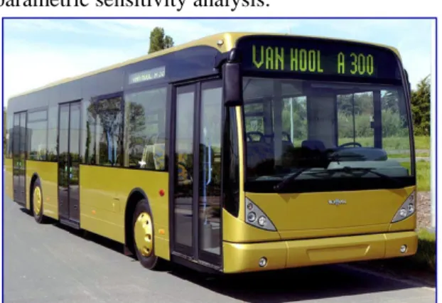
The simulated buses are based on the Vanhool A300 bus [17], illustrated in figure 7. It is a 12 meters length bus classically used by public transportation company in Belgium with 33 seats and a maximum capacity of 110 persons. It is powered by a 205 kW diesel Man engine.
This bus is modeled in ADVISOR using the conventional drivetrain configuration available in the standard library. Taking advantage of ADVISOR library, the bus is modeled using pre-existing components for buses or other heavy vehicles with only minor changes. The most important vehicle parameters are given in Table 1.
Table 1: Vanhool A300 characteristics
Engine Power 205 kW
Max Efficiency 44%
Aerodynamics S 7.24 m²
Cx 0.79
Tires Rolling resistance 0.00938
Rolling Radius 0.5 m
Curb weight mass 11280 kg
As no information on the original Man engine was available, it was substituted for our study by a 205 kW diesel engine from Detroit Diesel that is present in the library.
The total mass of the vehicle for simulation is the mass of the chassis plus a cargo mass. This one has been chosen arbitrary to 2475 kg which corresponds to 33 passengers of 75 kg. As the vehicle mass fluctuates a lot during the day with the number of passengers, the important impact on the fuel consumption and on the performance
of the bus [18, 19] will be assessed using a parametric sensitivity analysis.
The mechanical power consumption of the auxiliary systems is set to 9.3 kW according to literature [20].
The final drive ratio has been modified to give the bus a maximum speed of 100 kph.
The goal of the hybridization is to reduce the fuel consumption of the vehicle while keeping the same performances as the conventional vehicle. At first the vehicle has to be able to perform all the SORT drive cycles. The other performance criteria are defined as identical maximum speed (100 kph), acceleration time (0 to 60 kph test) and gradeability (maximum grade at 30 kph test) tests from Advisor.
4.2
HEV bus with batteries
The hybrid buses that are modeled and simulated in this study are parallel mild hybrid. This configuration is chosen to be consistent with the architecture of hybrid hydraulic bus and hybrid electric vehicle using super capacitors so that a fair comparison can be conducted. Indeed the parallel architecture is the best configuration to take advantage of the low specific energy of the hydraulic accumulator and low specific energy of the super capacitors. Batteries, which have a higher specific energy, would allow considering other technical solutions like parallel full hybrid or series hybrid.
In ADVISOR, the parallel configuration can be selected from the drivetrain menu. Compared to the conventional drivetrain, there are a couple of components to choose: the motor, the energy storage system and the powertrain control. The electric motor is chosen from the ADVISOR library among the AC induction motors AC75 family. The power of the motor will be determined by a parametric study.
The batteries retained for the simulation are nickel-metal hydride batteries also taken from the library. The NiMH batteries are high energy batteries that are used in standard commercial hybrid vehicle applications (e.g. Toyota Prius and Honda Insight). The size of the batteries will also be calculated thanks to the parametric study. The chosen powertrain controller is the parallel controller from ADVISOR.
For other characteristics, one notices also a few changes. The engine power is determined by the parametric study while the final drive ratio is adapted to the current power of the engine to keep the same maximum speed.
Because of high electrical energy source available on board, the consumption of the auxiliary systems is reduced from 9.3 kW to 5.25 kW [20] because one can save the efficiency of a converter.
The parametric study is carried out to determine the optimal sizing of the components to minimize the fuel consumption. The parameters of the study are the fuel converter torque scale (equivalent to the engine power), the motor torque scale (equivalent to the motor power) and the energy storage system number of modules (equivalent to the size of the storage system). It comes that an engine power of 150 kW, an electric motor of 39 kW and NIMH battery pack with 568 modules (8 blocks of 71 modules in parallel, which gives a voltage of 547V, an energy of 26.25 kWh and a mass of 567 kg) gives rise to a minimum fuel consumption while enabling the bus to have the same or even better performances than the conventional one. This bus has a hybridization rate of 20.6%.
4.3
HEV bus with super capacitors
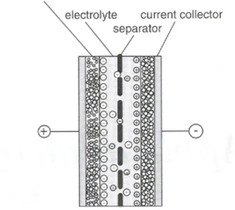
The super capacitors, whose principles are illustrated in figure 8, are double layer electrochemical capacitors [21] that have a remarkable high capacitance (several kilofarads).
Compared to batteries, super capacitors have a higher specific power but they have a smaller specific energy (see Ragone diagram presented in figure 9). The super capacitors fill in the gap between capacitors and batteries. The others great advantages of the super capacitors are their high charge/discharge efficiency and their very long service life
The model of HEV bus with super capacitors is very close to the model of HEV bus with batteries. The only important difference comes from the energy storage system characteristics. We chose the energy storage system based on a super capacitor component that is the Maxwell
BMOD0018-390V super capacitor module [22], modeled in ADVISOR by 153 super capacitor models from the library. The difference of mass between the real module and the model is introduced via a modification of the cargo mass. A new parametric study is conducted to determine the optimal component sizes, i.e. the
power of the engine, the power of the motor and the number of super capacitor modules. The optimal characteristics are the following. The diesel engine has a power of 160 kW, a little more than the engine of the HEV bus with batteries to compensate the smaller stored energy. The motor has a power of 64 kW a little more than the motor of the HEV bus with batteries to take advantage of the higher available electric power. The energy storage system is composed of two Maxwell modules that represent a useful energy of 0.564 kWh and a total energy of 0.752 kWh for a total mass of 330 kg. This bus has a hybridization rate of 28.6%. This design is close to the hybrid bus built by ISE Corporation and using two thunderpacks [23].
4.4
HHV bus
In a hybrid hydraulic vehicle the energy storage system consists of pressurized oil or water. The hydraulic circuit is composed of a low pressure reservoir, a high pressure accumulator and a reversible hydraulic machine operating in two modes, motor and pump. The basic principles of are HHV are drawn in figure 10: during braking phases, water or oil is pumped from the reservoir to the high pressure accumulator (the hydraulic machine is working as a pump). This energy stored is then used by emptying the accumulator through the hydraulic machine (working as a motor) when needed.
There is no model of hydraulic components in ADVISOR. So the hydraulic accumulators and the motor/pump models are derived by developing equivalent (fictitious) electric component models. As previously, the sizes of the energy storage system, the power of the engine and of the motor/pump are deduced from a parametric study.
Figure 7: scheme of a super capacitor
Figure 6: Ragone diagram of specific power and energy of different electrical storage systems
The storage system is composed of hydraulic accumulators, reservoirs and fluid. In this study, the hydraulic fluid is water because we investigates the applications of a novel design of reversible motor pump [11] that is able to work with water and does not need extra lubricant. The water has two main advantages on other hydraulic fluids such as oil: water has a very low cost and water is clean for the environment in case of leakage. Low pressure reservoir and high pressure accumulator can be found on the market. We selected here reservoir and accumulators for HYDAC catalogue [24]. The sizes of the reservoir and accumulator are based on parametric study aiming to minimize the fuel consumption. It comes that 5 hydac accumulators of 15 gallons, meaning that there is a maximum of 136 litres of fluid in motion. It leads to use a reservoir of 200 litres of capacity (for practical purpose: 4 hydac tanks of 50 l). This system can store 0.771 kWh of energy and weight 1194 kg. Hydraulic accumulator models in ADVISOR have been derived from the super capacitor model. The super capacitors are closer, from the specific energy and specific power points of view, to the accumulators than the batteries. In the model, an equivalent number of super capacitors is chosen to obtain the required energy while the mass difference between the two systems is introduced via the cargo mass of the vehicle.
As the reversible water motor pump is still under development and not fully characterized, we have selected a commercial product that has similar performance albeit using oil. The motor/pump is thus chosen among the large range of variable volume piston pumps built by Parker [25]. Our interest goes to the PE 60 that has a maximum power of 64 kW and weight 37 kg. The pump has also similar efficiency curves than the induction motor present in the ADVISOR library, so that the motor/pump model is tailored from the characteristic curves of an AC induction motor. However its mass has to be modified because the pump is lighter than the equivalent electric motor.
The parametric study recommends using a 160 kW diesel engine as primary energy converter for the HHV bus. This means that the bus has a hybridization rate of 28.6%. One can notice that the HHV configuration is close to the HEV bus with super capacitors. This comes from the
similitude in terms of power and energy between the hydraulic system and the super capacitors.
5 Results and comparisons
5.1
Fuel saving and performances
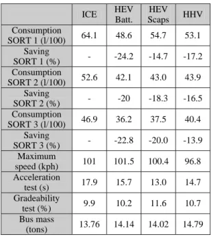
The summary of simulation result obtained with ADVISOR is given in the table 2. The different simulated configurations (conventional, HEV with batteries, HEV with super capacitors and HHV) are given in columns. The different tests are given through the lines: consumption for the three SORT cycles (in liters by 100 km), fuel saving compared to the conventional bus (in percents), maximum speed of the bus (in kph), acceleration test (time needed, in seconds, to accelerate from 0 to 60 kph), gradeability test (maximum slope, in percents, that the bus can climb at 30 kph during at least 10 seconds) and the weight of the bus (in metric tons). The weight of the bus is necessary to explain some performances.
Table 2: fuel consumption and performance of the different buses ICE HEV Batt. HEV Scaps HHV Consumption SORT 1 (l/100) 64.1 48.6 54.7 53.1 Saving SORT 1 (%) - -24.2 -14.7 -17.2 Consumption SORT 2 (l/100) 52.6 42.1 43.0 43.9 Saving SORT 2 (%) - -20 -18.3 -16.5 Consumption SORT 3 (l/100) 46.9 36.2 37.5 40.4 Saving SORT 3 (%) - -22.8 -20.0 -13.9 Maximum speed (kph) 101 101.5 100.4 96.8 Acceleration test (s) 17.9 15.7 13.0 14.7 Gradeability test (%) 9.9 10.2 11.6 10.7 Bus mass (tons) 13.76 14.14 14.02 14.79
First, we discuss the achievable performance by the hybrid buses and we compare it with the conventional bus.
The maximum speed of the two HEV is higher than the reference speed of 100 kph, while the HHV maximum speed is too low (3 %). By comparison with the HEV using super capacitors which is very close to the HHV in terms of stored energy and available power, the explanation appears to be the higher weight of the hydraulic system that increase the loss due to the rolling resistance. One quick calculation shows that the maximal reachable speed of the bus with these characteristics and using only the engine is approximately 108 kph. If the bus does not reach this speed, it is because of the transmission ratio.
The extension of the final drive ratio has been considered but it penalizes the acceleration and gradeability performances of the bus. The ideal solution consists to extend only the last gearbox reduction ratio.
In terms of acceleration, all the hybrid vehicles are clearly better than the conventional one (performance improvement from 12 to 27 %). In particular, the HEV with super capacitors that benefits from the high power and low weight of its secondary propulsion system.
All the hybrid buses have succeeded in the gradeability test and slightly improve (from 2 to 17 %) the results of the conventional bus.
5.2
Cost and payoff
In this last section, we discuss the development, fabrication and operating cost of the different hybrid systems. These costs are linked with the economies (fuel saving and economy on the maintenance of the braking system) allowed by the hybridization on the different cycles.
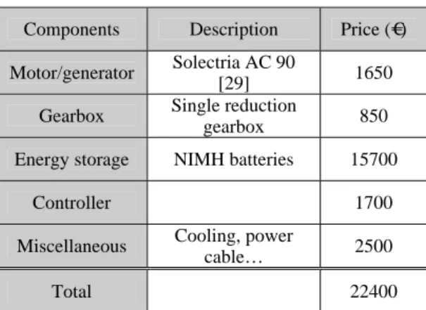
The cost estimation of the components of these systems is mainly based on three studies [26, 27, 28]. The expected cost for the components of the HEV with batteries, the HEV with super capacitors and the HHV bus are shown respectively in table 3, 4 and 5. The energy storage system is responsible for an important part of the total cost of the hybrid system (from 45 to 70 % of the cost). It is the price of the storage system that is responsible for the important difference of costs between some studied solutions. The batteries are far more expensive than the two other systems but they enable to store more energy and to obtain a better fuel economy.
Table 3: cost estimation of the hybrid electric system with batteries
Components Description Price (€)
Motor/generator Solectria AC 90
[29] 1650
Gearbox Single reduction
gearbox 850
Energy storage NIMH batteries 15700
Controller 1700
Miscellaneous Cooling, power
cable… 2500
Total 22400
Another very important point is the service life time of the system. The super capacitors and the hydraulic accumulators can perform a huge number of charge/discharge cycles and it is reasonable to consider that they do not need to be replaced during the life of the bus. The case of the NIMH batteries is different. The batteries can not accept as much charge/discharge cycles and it is also recommended to avoid deep discharge
of the batteries to protect their life time. This is one of the reasons why the energy of the battery pack is so important compared to the energy of the other systems. A normal service life for a battery system of a hybrid bus is evaluated at 6 years [30]. So a fraction of the cost of a new battery pack is included in the annual cost of the HEV with batteries.
Table 4: cost estimation of the hybrid electric system with super capacitors
Components Description Price (€)
Motor/generator Solectria AC 120
[29] 2700
Gearbox Single reduction
gearbox 850
Energy storage 2 * Maxwell [22]
BMOD0018-390V 6400
Controller 1700
Miscellaneous Cooling, power
cable… 2500
Total 14150
Table 5: cost estimation of the hybrid hydraulic system
Components Description Price (€)
Motor/pump Parker PE60 [25] 1800
Gearbox Single reduction
gearbox 850
Energy storage Hydac
SB600+SB40 [24] 8900
Controller 1700
Miscellaneous Cooling, pipe… 2500
Total 15750
To the price of the components, the final price of the hybrid systems has to include the fabrication cost (estimated here at 15 % of the components cost) and the cost to develop the system. The total development cost for one of these hybrid systems, including the fabrication of one prototype, has been estimated to 2,000,000 € [26]. If we count on the fabrication of 1,000 vehicles, which is a reasonable for a bus manufacturer, it implies an extra cost of 2,000 € per bus to pay off the development cost.
The hybrid system adds an important extra cost to the vehicle in the counter part of reducing the annual cost of fuel and braking system maintenance. The economy on the braking system is evaluated at 850 € by year [26]. The annual saving on the fuel cost is calculated on the basis of the fuel prize (the average prize of one litre of diesel, in Belgium, for the year 2007, is 1.094 € [31]), an annual traveled distance of 45000 km [17] and the fuel economy realized on one of the SORT cycles. It implies that since
there are three SORT cycles, there are three simulated fuel consumptions and thus three different payoff periods.
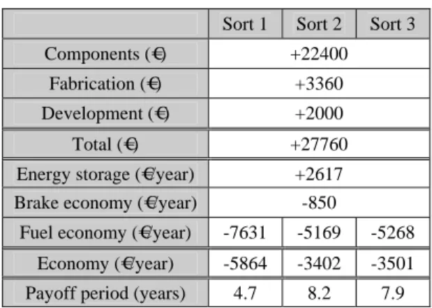
The expected payback period of the HEV with batteries, the HEV with super capacitors and the HHV bus are shown respectively in table 6, 7 and 8.
Table 6: payback period estimation for the HEV bus with batteries
Sort 1 Sort 2 Sort 3
Components (€) +22400
Fabrication (€) +3360
Development (€) +2000
Total (€) +27760
Energy storage (€/year) +2617
Brake economy (€/year) -850
Fuel economy (€/year) -7631 -5169 -5268
Economy (€/year) -5864 -3402 -3501
Payoff period (years) 4.7 8.2 7.9
Table 7: payback period estimation for the HEV bus with super capacitors
Sort 1 Sort 2 Sort 3
Components (€) +14150
Fabrication (€) +2123
Development (€) +2000
Total (€) +18273
Energy storage (€/year) 0
Brake economy (€/year) -850
Fuel economy (€/year) -4628 -4726 -4628
Economy (€/year) -5478 -5576 -5478
Payoff period (years) 3.3 3.3 3.3
Tableau 8: payback period estimation for the HHV bus
Sort 1 Sort 2 Sort 3
Components (€) +15750
Fabrication (€) +2363
Development (€) +2000
Total (€) +20113
Energy storage (€/year) 0
Brake economy (€/year) -850
Fuel economy (€/year) -5415 -4283 -3200
Economy (€/year) -6265 -5133 -4050
Payoff period (years) 3.2 3.9 5
The hydraulic system and the super capacitor system are quite close in terms of payoff. The payback period in heavy urban traffic of the HHV is a little shorter than the one of the HEV with super capacitors. But the HEV is better in easy urban and suburban cycles with the
advantage that the payoff period is the same for every kind of driving conditions.
From the economical point of view, the HEV using batteries is penalized, compared to the two others hybrid systems, by the cost of the batteries and the cost for renewing the batteries. That does not mean that the technology is not profitable but it takes more time to get its investment back than with the other solutions.
6 Conclusions
This study compares from a technical and economical point of view three different hybrid solutions adapted to an urban bus. It has of course its limitations. For example, the hybridization rate and the size of the storage system of one given solution has been chosen in order to have the minimal fuel consumption. Other criteria, like the cost of the storage system, could be use instead or in conjunction with this criterion. The cost of the components is based on a review of the literature and not on real data from the manufacturers.
Nevertheless, this work has shown that all the solutions offer significant reduction of fuel consumption (from 13.9 to 24.2 %) and that they can all be economically profitable in a quite short period (from 3.2 to 8.2 years). It allows also highlighting the advantages and drawbacks of each hybrid system.
The HEV using batteries is the best solution from the pure consumption and CO2 emissions points
of view. Moreover, this system is compatible with more radical solutions like full hybrid and ZEV mode. But its commercialization is penalized by the prize of the battery pack and its limited service life that imposes the replacement and the recycling of the batteries.
The HEV using super capacitors offers a short payoff period in every driving conditions and a long service life. Furthermore, the cost of the super capacitors will decrease more and more in the coming years. But for the moment, the super capacitors technology remains very new and experimental. Another disadvantage is that it is not adapted to other hybrid configurations. The HHV has a good payback, in particular in heavy urban traffic. The hydraulic storage system has reached an industrial maturity and has a very long life time. But it is penalized by its important weight and, as the HEV with super capacitors, it is not compatible with full hybrid solutions.
References
[1] IPCC Intergovernmental Panel on Climate Change, http://www.ipcc.ch, accessed 2008-01
[2] UNFCCC United Nations Framework Convention
on Climate Change, http://unfccc.int, accessed 2008-01
[3] L. Bastard, Managing oil demand in transport Key
messages from SMP 2030, presentation to
IEA-EMCT workshop, February 2005
[4] WHITE PAPER European transport policy for 2010:
time to decide,
http://ec.europa.eu/transport/white_paper/, accessed 2008-01
[5] C.C. Chan, The state of the art of electric and hybrid
vehicles, Proc. IEEE, vol 90 pp.247-275 2002
[6] G. Genta, The motor vehicle dynamics: modeling and
simulation, World Scientific, 1997
[7] Z. Filipi, L. Louca, B. Daran, C.-C. Lin, U. Yildir, B. Wu, M. Kokkolaras, D. Assanis, H. Peng, P. Papalambros, J. Stein, D. Szkubiel, and R. Chapp,
Combined optimisation of design and power management of the hydraulic hybrid propulsion system for the 6x6 medium truck, Int J. of Heavy
Vehicle Systems Vol. 11, Nos 3-4, pp 372-402. 2004 [8] Wu B., C.-C. Lin, Z. Filio, Peng H. et Assanis D.,
Optimal power management for a hydraulic delivery truck, Vehicle System Dynamics Vol. 42 Nos 1-2,
pp 23-40. 2004
[9] Kepner R., Hydraulic power assist – demonstration
of hydraulic hybrid vehicle regenerative braking in a road vehicle application, SAE Paper
2002-01-3128
[10] Matheson P. and Stecki J., Development and
simulation of a hydraulic hybrid powertrain for use in commercial heavy vehicles, SAE Paper
2003-01-3370, 2003
[11] F. Van Loo, S. Christiaens, J Nzisabira, P. Mathieu and P. Duysinx, Technical and economical study of
a new hydraulic motor pump, ENERCARE Project
Technical Report for the Walloon Region of Belgium 2005 (in French)
[12] Y. Louvigny, J. Nizisabira, P. Duysinx, Analysis of
hydraulic hybrid vehicles and economical comparison with hybrid electric vehicles,
Proceedings of EET2007, Brussels, May 2007 [13] NREL National Renewable Energy Laboratory,
http://www.nrel.gov, accessed 2008-01
[14] AVL, http://www.avl.com, accessed 2008-01
[15] T. Markel, A. Brooker, T. Hendriks, V. Johnson, F. Kelly, B. Kramer, M. O’Keefe, S. Sprik, K.Wipke,
ADVISOR: a systems analysis tool for advanced
vehicle modeling, Journal of Power Sources,
110(2002), 255-266
[16] UITP, Union internationale des transports publics, http://www.uitp.org, accessed 2008-01
[17] Vanhool, http://www.vanhool.be, accessed 2008-01
[18] N. Andreu, Simulation et étude
technico-économique comparative de bus hybrides électriques et hydrauliques, master thesis,
University of Liège, 2006
[19] A. Olivares, Simulation et étude
technico-économique comparative de bus hybrides hydrauliques et électriques avec supercondensateurs, master thesis, University of
Liège, 2007
[20] C. Andersson, On auxiliary systems in commercial
vehicles, doctoral dissertation, Lund University,
2004
[21] E. Frackowiak, Development of high voltage super
capacitor materials, presentation to COST-542
action in Liège, September 2006
[22] Maxwell, http://www.maxwell.com, accessed
2008-01
[23] T. Bartley, Ultracapacitors and batteries for energy
storage in heavy-duty hybrid electric vehicles,
presentation to the 22nd international battery seminar and exhibit in Fort Lauderdale, March 2005
[24] Hydac, http://www.hydac.com/, accessed 2008-01
[25] Parker hydraulic pump/motor division, http://www.parker.com/ead/cm1.asp?cmid=261, accessed 2008-01
[26] P. Drozdz, Hybrid refuse truck feasibility study, Technical Report for the Transportation development centre of transport Canada, September 2005
[27] Analysis and forecast of the performance and cost of
conventional and electric-hybrid vehicles, Technical
Report for the California Energy Commission, February 2002
[28] J. Auer, G. Sartorelli, J. Miller, Ultracapitors –
improving energy storage for hybrid vehicles,
Proceedings of EET2007, Brussels, May 2007 [29] Azure dynamics Solectria AC motors,
http://www.azuredynamics.com, accessed 2008-01 [30] Allison transmission hybrid system,
http://www.allisontransmission.com/product/electric drive, accessed 2008-01,
[31] Petrolfed fédération pétrolière belge, http://www.petrolfed.be, accessed 2008-01,
Authors
Yannick Louvigny obtained its engineering diploma in the field of electro-mechanic from the University of Liege (Belgium) in 2006. Now, he is working as a research assistant in the automotive engineering lab of the university. His research interests incorporate engine dynamic, fuel cell, hybrid vehicles and clean transportation in general.
Jonathan Nzisabira obtained his master in Engineering Sciences from the University of Liege. His research interests include hybrid electric vehicle simulation and optimization. He works now (for a graduate) on clean propulsion technologies. He participate actively in transportation projects organized by the Walloon region After his Electro-mechanical Engineering degree at University of Liege (Belgium) in 1990, Pierre Duysinx obtained his PhD in Structural optimization from the same University in 1996. He worked as an Assistant Professor at Danish Technical University (DTU) in Copenhagen in 1996 and at University of Liege from 1999. In 2003, he was promoted Professor at University of Liege and became head of Automotive Engineering lab. Research interests are advanced simulation and optimization methods for vehicle design and clean propulsion technologies.
![Figure 1: part of the transport sector in the CO2 emissions [3]](https://thumb-eu.123doks.com/thumbv2/123doknet/5643064.136491/1.892.534.728.745.971/figure-transport-sector-co-emissions.webp)