HAL Id: hal-01662699
https://hal.archives-ouvertes.fr/hal-01662699
Submitted on 7 Dec 2018
HAL is a multi-disciplinary open access
archive for the deposit and dissemination of
sci-entific research documents, whether they are
pub-lished or not. The documents may come from
teaching and research institutions in France or
abroad, or from public or private research centers.
L’archive ouverte pluridisciplinaire HAL, est
destinée au dépôt et à la diffusion de documents
scientifiques de niveau recherche, publiés ou non,
émanant des établissements d’enseignement et de
recherche français ou étrangers, des laboratoires
publics ou privés.
Influence of isothermal aging conditions on APS TBC’s
interfacial fracture toughness
Yankuan Liu, Yinghui Liu, Philippe Lours, Thierry Sentenac, Vanessa Vidal,
Zhiping Wang, Kunying Ding
To cite this version:
Yankuan Liu, Yinghui Liu, Philippe Lours, Thierry Sentenac, Vanessa Vidal, et al.. Influence of
isothermal aging conditions on APS TBC’s interfacial fracture toughness. Surface and Coatings
Tech-nology, Elsevier, 2017, 313, pp.417-424. �10.1016/j.surfcoat.2017.01.008�. �hal-01662699�
Influence of isothermal aging conditions on APS TBC's interfacial
fracture toughness
Yankuan Liu
a,⁎
, Yinghui Liu
b, Philippe Lours
b, Thierry Sentenac
b, Vanessa Vidal
b,
Zhiping Wang
a, Kunying Ding
aaTianjin Key Laboratory of Civil Aircraft Airworthiness and Maintenance, Civil Aviation University of China, Tianjin, China bUniversité de Toulouse, CNRS, Mines Albi, INSA, UPS, ISAE, ICA (Institut Clément Ader), Campus Jarlard, F-81013 Albi, France
a b s t r a c t
Interfacial toughness is an important factor to address thermal barrier coating's (TBC) durability. In this paper, a promising method, based on interfacial indentation, is used to analyze apparent interfacial toughness of TBC de-posited by Atmospheric Plasma Spray (APS). The specimens made by APS were treated using different oxidation holding times and temperatures, namely 1050 °C-100 h, 1100 °C-100 h, 1050 °C-300 h and 1100 °C-300 h, re-spectively. The morphology of the interface between the TBC and the underlying bond coat was analyzed by Scanning Electron Microscopy (SEM). Results have shown that the fracture toughness of the interface between the bond coat and the top coat decreased as the oxidation conditions become more severe that is the temperature and/or to a lesser extent the exposure time is increased. Simultaneously, the thickness of the thermally grown oxide (TGO) generated on top of the aluminum reservoir bond coat increases as well. The TGO is a “double layer” oxide successively composed of a first scale of Al2O3close to the bond coat and a second scale of CoCrNiO
close to top coat. In addition, it was also found that the possible thermally activated spallation of APS TBC's system occurs in the zone of the TGO layer, especially within the CoCrNiO oxide scale. Consequently damage of APS sys-tems is shown to initiate at the interface through complex mechanism of delamination in relation with both the toughness and the microstructure of the interface. In order to inhibit the growth of the detrimental CoCrNiO oxide and in turn favors the development of a dense and stable alumina scale, a Supersonic Fine Particles Bombarding (SFPB) method was used to optimize the quality of APS coating.
Keywords:
APS (Atmospheric Plasma Spray) TBC (thermal barrier coating) Interfacial indentation TGO (thermally grown oxide) Interfacial fracture toughness
Supersonic Fine Particles Bombarding (SFPB)
1. Introduction
TBCs (thermal barrier coating) are widely used in components oper-ating at high temperature such as gas turbines and aero-engines. The objective of TBCs is to protect and insulate the underneath metallic parts in order to permit specific design able to be run under optimized high temperatures, thus increasing turbine efficiency. Even though TBC systems allow superior improvement of component performance
[1,2], thermal strains and stresses resulting from transient thermal gra-dients developed during in-service thermal and mechanical cyclic expo-sure limit the durability of the multi-material system, often by provoking early cracking and detrimental spallation of the protective deposit.
The adherence properties of TBC systems usually decrease following exposure at high temperature because of the growth of a TGO (thermally grown oxide) layer in service and the development of residual stress in the TBC[3,4]. This layer, acting as a diffusion barrier, generally exhibits
roughly parabolic growth kinetics, until either out-of-plane or in-plane cracking develops, which stands as the onset to the degradation usually through the detachment and ejection of TBC or TBC plus TGO particles. Consequently, this spallation-induced damage strongly limits the lifetime of the TBC systems. As a matter of fact, the interfacial toughness, indicat-ing the capacity of the system to resist to the initiation and propagation of cracks throughout the TGO or at the interface that the TGO develops either with the top coat or the bond coat, is one of the most important factors to assess for the durability of TBC systems[5]. According to differ-ent manufacturing approaches and various aging conditions, several specific interfacial toughnesses and spallation location in relation with microstructural details such as rumpling, barbules development, have been investigated[6,7].
Following aging, different crack locations, mainly controlled by the bond coat composition and the top coat deposition methods, are identi-fied. In sol-gel TBC, defects occur within the YSZ (Yttria-Stabilized Zirco-nia) layer as well as at the bond coat/TGO interface or even within the TGO itself[6]. Meanwhile, the EB-PVD (Electron Beam Physical Vapor Deposition) TBC delaminates mainly between the bond coat/TGO inter-face for TGO layers thicker than circa 3 μm and at the TGO/top coat
⁎ Corresponding author.
interface for thinner TGO[8], In this paper, a complete TBC system has been developed including not only the top coat but also the bond coat both deposited using the APS (Atmospheric Plasma Spraying) method. In some cases and for the purpose of comparison, an additional step of surface modification, namely Supersonic Fine Particles Bombarding (usually SiO2particles) (SFPB) has been implemented on bond coat
prior to the final deposition of the top coat. As the consequence, grain refinement and enhancement of the dislocation density occurring in APS-SFPB barriers, provide short-circuit for the diffusion of aluminum, thus changing the nature of the TGO as compared to that grown on sim-ple APS barriers.
The TBC system produced either by APS or APS-SFPB is a layered multi-material. The system is composed of the nickel base superalloy substrate, a sub-layer (bond coat) of MCrAlY and a ceramic layer (top coat) of YSZ. The main degradation of this type of system is due to an al-teration of the adhesion at interfaces of the thermal barrier as a conse-quence of isothermal oxidation (physical-chemical) or cyclic oxidation (thermo-mechanical)[9].
In this paper, specimens have been oxidized according to various isothermal aging conditions in order to grow oxide scales with different thicknesses and different proportions of Al2O3versus CoCrNiO. Using
in-terfacial indentation test[10,11,12], interfacial toughness of specimens relative to the different aging treatments were explored respectively. 2. Experimental
Substrates are cylinders with a diameter of 25 mm and a thickness of 5.6 mm. The substrate material is a nickel based alloy-718, whose chem-ical composition and physchem-ical properties are given inTables 1 and 2 re-spectively. CoCrAlY powders were used to prepare the bond coat whose thickness is 220 μm. CoCrAlY is composed of 23 wt% of chromium (Cr), 13 wt% of aluminum (Al), 0.5 wt% of yttrium (Y) and remaining cobalt (Co). YSZ powders were used to deposit the top coat, the thickness of this layer is 330 μm. The typical equilibrium YSZ components are 93 wt% and 7 wt% of ZrO2and Y2O3respectively.
The equipment used to prepare the TBC is the Control System APS 3710 model manufactured by PRAXAIR, US. To ensure a consistent and accurate distance and projection speed, the model 2400M six axes robot automatic hand manufactured by ABB was utilized for spraying. The spraying parameters are given inTables 3 and 4:
Isothermal oxidation tests may be classified into four (4) groups, all conducted in the same furnace. Two (2) groups are carried out for 100 h exposure time and oxidation temperatures of 1050 °C and 1100 °C, re-spectively. The other two (2) groups correspond to a longer exposure time, i.e. 300 h and to the same oxidation temperatures that is, 1050 °C and 1100 °C, respectively.
The cross sections of the coated specimens were investigated by Scanning Electron Microscopy (SEM) to reveal details of the morpholo-gy, the possible damage and the overall microstructure. The coatings were evaluated by X-ray diffraction using a Bruker D8 Advance with Cu-Kα radiation to detect and analyze the different phases. The hard-ness and Young's modulus values of the coatings (bond coat and top coat) were obtained by using a CSM Indentation Tester and nano-in-denter (Berkovich innano-in-denter).
For bi-materials, a simple model basically based on a rule of mixtures to quantitatively measure the apparent toughness of the interface, is proposed in[13]for hard coatings. It is shown that the apparent
toughness of the interface (Kca) can be calculated by using the following
formula: Kca¼ 0:015aPc c3=2 E H ! " I1=2 ð1Þ
where:Pcis the critical value (in Newton) of the load P exerted using
Vickers indentation at the interface between the two materials of the system and acis the critical crack size (in meter). They both correspond
to the values of load and crack size related to the initiation of cracking at the interface due to indentation.
The value of the ratio ðE HÞ
1=2
I relative to the interface between the
bond coat and the top coat is given by the following equation: E H ! "1=2 I ¼ E H # $1=2 S 1 þ HS HTC % &1=2þ E H # $1=2 TC 1 þ HTC HS % &1=2 ð2Þ
where subscripts S and TC stand for substrate (bond coat) and top coat (ceramic layer), respectively.
The methodology relies on the determination of the threshold force or critical load Pcrequired to initiate a crack with a critical size ac. If the
applied load is lower than Pc, only the indent resulting from the
inden-tation is observed. If it is higher than Pc, a crack originating from the
in-dent is formed. The length of the crack increases with the applied load. For very high load, the complete TBC delamination can occur. Then, from the values of Pcand crack length, the apparent interfacial
tough-ness (Kca) is calculated using Eq.(1)with the value of ðHEÞ 1=2
I determined
from Eq.(2). The method employs a pyramidal indenter and can be ap-plied for a large range of coating thicknesses (greater than 100 μm). Typically, it is specifically used for investigating adhesion of TBC systems
[14]. For one specimen on a given treatment condition, each indentation load P generates a square-shaped indent imprint with diagonal b and, if any (when P ≥ Pc) a crack with size a (a ≥ ac). Four (4) to five (5)
inden-tations were performed for each load to be as representative as possible and minimize error. Note that to transpose the approach developed in
[13]for bi-materials to the case of TBC systems, the thickness of the TGO on which the indentation is performed can be considered much lower than the size of the imprint. The influence of the TGO is thus rea-sonably neglected[7], which is perfectly justified for most cases includ-ing as-received condition, all oxidations at 1050 °C and 100 h oxidation at 1100 °C and to a lower extent for the most time and thermally activat-ed oxidation (1100 °C/300 h). In addition, the method does not take into account the possible metallurgical evolution of both the bond coat and the TBC during high temperature exposure. However, at least in the frame of the approach essentially comparative developed in the paper and as far as the interface is only involved in the mechanical response
Table 1
Weight percent composition of nickel based alloy-718.
Alloy C Cr Mo Fe Nb Ti Al P B Ni
Ni-718 0.125 18 2.8 18 5.4 1 0.5 0.006 0.004 Balance
Table 2
Physical properties of the nickel based alloy-718.
Alloy Young's modulus Poisson's coefficient
Ni-718 204 GPa 0.3
Table 3
Parameters for preparing the CoCrAlY bond coat.
Item Gas Value
Primary gas/PSI Ar 60 Secondary gas/PSI He 120 Carrier gas/PSI Ar 40 Current/A 835 Voltage/V 38 Spray distance/mm 85
Gun moving velocity/mm·s−1 450
of the system, the method can be beneficially used to estimate the ap-parent interfacial toughness. Quantitative approach is derived by plot-ting two lines, i.e. lnP versus lnb (the so-called hardness line) and lnP versus lna (the so-called induced-crack line). The intercept between the two lines gives the critical load Pcand the critical crack size ac. The
values of a and b are initially measured by SEM (Fig. 1). 3. Results and discussion
Hardness and Young's modulus of both the bond coat and the top coat tested by Berkovich method are shown inTable 5. They are issued from images and elastic force-displacement curve as shown for the top coat inFig. 2(a) and (b). The principle of the measurement is based on the depth-controlled indentation of the material. Once the fixed pene-tration (here 2 μm) is reached, the load is kept constant for a short time (in our case under a force of 460 nN), giving rise to a slight material relaxation. The force is then released to retrieve the elastic strain pro-duced by the indentation. The hardness and Young's modulus are re-spectively appreciated by measuring the size of the indent imprint and the slope of the elastic curve upon stress release.
The linear relationship between (lnb) and (lnP) (Fig. 3) showing a slope close to 0.5 (calculated to be 0.485) is in good agreement with the general standard formula relating the Vickers hardness (HV) of bulk materials to the ratio between the applied load P and the square of the diagonal length d2.
The general formula of the Vickers hardness is: Hv ¼1:8544F
d2 ð3Þ
where F is the applied load for the indentation and d is the diagonal length of the indentation imprint, (note that in the case presented here F = P and d = b). so : d2¼1:8544FHv ð4Þ giving: ln dð Þ ¼12 ð Þ þF 12 ln 1:8544Hv ! " ð5Þ then: ln bð Þ ¼12 ð Þ þ KP ð6Þ with Ka constant K ¼12 ln 1:8544 Hv ! " ð7Þ InFig. 3is plotted the curve gathering the whole set of hardness data obtained for the whole bunch of specimens, respectively aged and non-aged, the so-called master curve. As this master curve basically
Table 4
Parameters for preparing the YSZ top coat.
Item Gas Value
Primary gas/PSI Ar 60 Secondary gas/PSI He 120 Carrier gas/PSI Ar 30 Current/A 860 Voltage/V 38.7 Spray distance/mm 72
Gun moving velocity/mm·s−1 250
Powder source speed/RPM 4.0
Fig. 1. Principle for measuring 2a (crack size) and 2b (indentation imprint size) by Scanning Electron Microscopy.
Table 5
Values of hardness and Young's modulus measured by nano-indentation (Berkovich).
Layer Hardness (HV) Young's modulus (GPa)
Top coat 587 73.5
Bond coat 485 125.5
Fig. 2. Imprint of the nano-indentation (Berkovich) (a), and load-penetration and relaxation curve in the top coat (b).
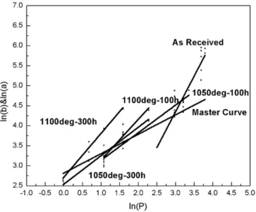
corresponds to a typical hardness curve, the slope (roughly 0.5) is un-changed independently of the aging condition. It was also confirmed that the position of the straight line is independent of the aging temper-ature and holding time. Both conditions justify to gather all values on a same master curve[8]. As well, crack curves (lna) versus (lnP) giving the evolution of the load-induced crack length for the various oxidation conditions tested are superimposed to the graph. Note that for given ox-idation time and temperature, that is a given oxox-idation thickness, the variation of the length a of the indentation-induced crack versus the ap-plied load P also fits a single regression line in a Log-Log scale. This can beneficially serve to evaluate the critical load Pcnecessary to initiate
in-terfacial detachment. The principle for the graphical determination of this critical load is given inFig. 3where both the (lnb)–(lnP) and the various (lna)–(lnP) lines corresponding to all oxidation conditions are plotted. The intercept between the master curve (hardness curve) and the crack curves discriminates the two domains where the applied load is respectively, i) too low to initiate interfacial cracking, ii) high enough to provoke the initiation and the propagation of an interfacial crack. This procedure can be repeated as often as necessary to deter-mine graphically the critical load for each condition, i.e. each oxide thickness. For the cases shown inFig. 3, results in terms of line slope and linearity are given inTable 6and critical load Pc, critical crack size
ac, apparent toughness Kcaand oxide thickness ζ are given inTable 7.
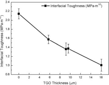
As expected, the critical load to efficiently indent the interface between the CoCrAlY bond-coat and the YSZ top-coat and subsequently produce a measurable interfacial crack, as well as the interfacial toughness, de-crease with the severity of the high temperature exposure (Fig. 4) and the thickness of the TGO that grows according to a thermally activated process (Fig. 5). It can be noticed that the values of the interfacial tough-ness for all conditions are significantly lower in the case of APS TBC than for EB-PVD as reported in[8]suggesting a lower resistance to crack ini-tiation and propagation for APS systems.
Besides, the toughness of the YSZ layer is about 1.970 MPa·m1/2[15],
which is nearly the same as the interfacial toughness of as-received specimen and higher than those of specimens corresponding to the dif-ferent aging conditions. This can explain satisfactorily why failure oc-curs systematically at the interface through a combined process of delamination and spalling but not within the ceramic itself. This type of adhesive failure is favoured at the expense of a purely cohesive failure within the barrier itself because the interface is less resistant to crack initiation and propagation than the YSZ top coat.
Fig. 6presents the morphology and microstructure of the oxide ther-mally grown between the bond coat and the top coat following isother-mal oxidation at 1050 °C during 100 h.
The oxide layer (TGO) is composed of two layers, respectively shown in dark (layer 1) and light (layer 2) contrast on the SEM micrograph in
Fig. 6.Figs. 7 and 8show the elemental composition determined by EDS (Energy Dispersive Spectroscopy) for layer 1 and layer 2. The mass ratio of Al/O for layer 1 is 50.17/42.77, which is pretty close to the ratio for the stoichiometric alumina Al2O3(1.125) suggesting that the main
compo-nent in layer 1 is Al2O3, formed during high temperature exposure using
the aluminum contained in the bond coat reservoir. In layer 2, in addi-tion to Al and O, large amounts of Co, Cr and Ni are identified, giving rise to the occurrence of a complex thermally grown oxide. The forma-tion of such oxide cannot be due to the exhausforma-tion of Al, as the temper-ature and the exposure time are both too low to generate the full depletion of the Al reservoir.
This is because, before the final formation of the Al2O3oxide layer,
the elements Co, Ni and Cr were filtered through Al2O3in the ceramic
layer and with the increase of heating time, the elements have had an oxidation reaction thus generating a CoCrNiO layer.
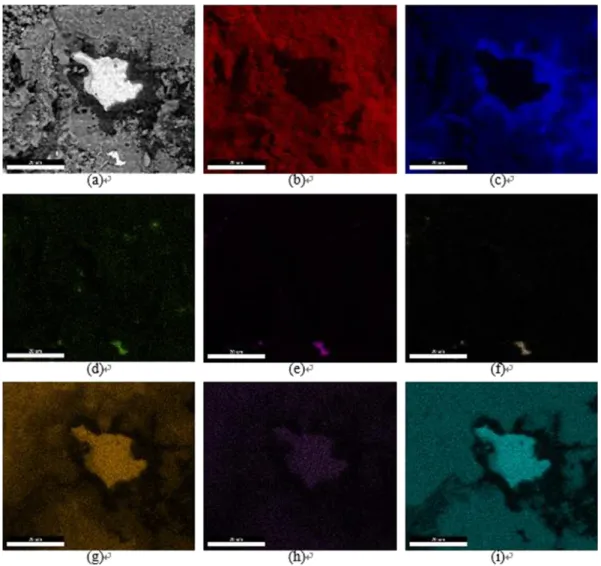
Fig. 9details the elements distribution at the surface of a failed spec-imen as revealed by Energy Dispersive X-ray Spectroscopy (EDS). Only a spot in the centre of the image, showing nickel, is relative to the bond
Fig. 3. Graphic determination of critical loads causing delamination of the thermal barriers.
Table 6
Equations of curves under different conditions.
Conditions Equations Linearity (correlation coefficient R values) Master curve ln(b) = 0.485ln(P) + 2.817 0.966 As-received ln(a) = 1.783ln(P) − 1.000 0.834 1050 °C-100 h ln(a) = 0.690ln(P) + 2.446 0.963 1100 °C-100 h ln(a) = 1.018ln(P) + 2.124 0.880 1050 °C-300 h ln(a) = 0.712ln(P) + 2.540 0.848 1100 °C-300 h ln(a) = 1.094ln(P) + 2.715 0.981 Table 7
Critical load, critical crack size, interfacial toughness and thickness of the TGO for the dif-ferent oxidation conditions.
Conditions Pc(N) ac(μm) Kac(MPa·m1/2) ζ (μm) As-received 18.935 69.69 2.14 0 1050 deg-100 h 6.110 40.25 1.57 5.79 1100 deg-100 h 3.670 31.41 1.38 9.64 1050 deg-300 h 2.718 25.84 1.36 9.17 1100 deg-300 h 1.182 18.14 1.01 15.1
coat. Note that elements constituting the top coat, namely yttrium and the zirconium, are rarely observed except concomitantly on very local-ised zone. Al2O3and CoCrNiO oxides, mainly cover the surface of the
spalled specimen in a complementary way. Cobalt and chromium can be observed on most parts of the image. Aluminum seems also rather homogeneously distributed, but only the zone around the centred spot is intense. The rest of the observed aluminum distribution can be the result of electron-specimen interactions where the thickness of the CoCrNiO is not high enough to efficiently limit the phenomenon.
Fig. 10shows the example of a specimen where crack is located within the CoCrNiO layer. Actually, indentation is initially applied on the Al2O3layer, and as a consequence cracks initiates from the Al2O3
layer or the Al2O3/bond coat interface. However, it ends up almost
every time within the CoCrNiO layer, which suggests that crack propa-gation is easier in the CoCrNiO layer than in the Al2O3layer.
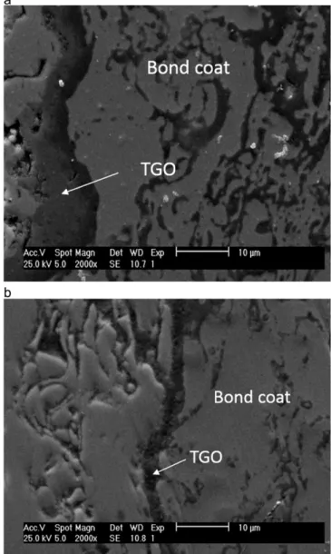
The SEM images ofFig. 11(a) and (b) showing the exact location of the APS TBC's spallation, correspond to two cracked specimens respec-tively aged 300 h at 1050 °C and 300 h at 1100 °C. The images show clearly that the spallation occurs in the TGO layer. It initiates and
extends within the CoCrNiO layer eventually resulting in a separation of the top coat and the bond coat.
Spallation of APS TBC's system is mainly located within the TGO layer. The results of interfacial toughness show that cracks propagate preferentially in the CoCrNiO. This is the reason why fragments of CoCrNiO layer remain on most part of the surface of the spalled speci-mens. The toughness of the CoCrNiO layer decreases when the aging condition becomes more severe in term of temperature and/or holding time.
Fig. 12(a) and (b) show the TGO morphology after aging 100 h at 1050 °C for an APS coating and an APS-SFPB coating, respectively. Con-trarily to the case of APS coatings where the thermally grown oxide is a complex multi-layered scale, the TGO in APS-SFPB coatings only con-sists in a thin, black-contrast Al2O3layer. Fine particles bombarding of
the bond coat has produced a significant grains refinement and a huge enhancement of dislocation density, which drastically increase the dif-fusion channels for Al[16]. It is expected to obtain a more compact and stable oxide layer with a straightforward reduction of the diffusion of Co, Ni and Cr.Fig. 13shows the XRD patterns (X-ray diffraction) in the TGO region for specimens oxidized 100 h at 1050 °C. Note that no Ni(Cr,Al)2O5is identified within the APS-SFPB coating.
The optimized morphology and composition of the oxide scale grown at the interface between the bond coat and the top coat should unambiguously improved the lifetime of the TBC upon thermal cycling. The interfacial toughness should as well be increased by such a promis-ing treatment, leadpromis-ing to a better resistance to spallation and degrada-tion. Lifetime of APS and APS-SFPB coatings were tested in cyclic conditions, following successive 30 minute heating at 1050 °C and
Fig. 5. Evolution of the interfacial toughness as a function of the oxide thickness.
Fig. 6. Oxide morphology.
Fig. 7. EDS peaks in TGO zone-1.
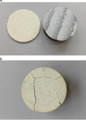
subsequent cooling by pulsed air for 5 min.Fig. 14shows macro-photo-graphs of the failure for TBCs processed by simple APS and APS-SFPB. The number of cycles to failure for the APS coating is 230 where the TBC fully detaches from the substrate, indicating a sudden and entire spallation of the barrier. For the APS-SFPB coatings, the numbers of cy-cles to failure is higher, reaching 350, and the mode of failure appears to be slightly different as only cracks are observed at this stage, the bar-rier remaining partly adherent to the substrate in this case.
4. Conclusion
Interfacial indentation has been employed to address interfacial ad-hesion and derive interfacial toughness in TBC (thermal barrier coat-ings) systems produced by Atmospheric Plasma Spray technique, after various isothermal aging, in the temperature range 1050 °C–1100 °C and holding times from 100 to 300 h. As compared to the as-deposited, unaged TBC, it is shown that the toughness degrades with both the ox-idation time and temperature, remarkably decreasing quasi-linearly with the thickness of the TGO (thermally grown oxide) that develops upon holding at high temperature. Typically for APS processed TBC, the TGO is a multi-scale oxide composed of successive layers of Al2O3
and CoCrNiO. It is shown that the measured interfacial toughness for aged TBC is systematically lower than the toughness of the top coat resulting in a preferential path for crack-induced spallation along the
Fig. 9. SEM image and EDS map of a failed specimen's surface after isothermal oxidation at 1100 °C-300 h. (a) SEM image, (b) oxygen, (c) aluminum, (d) yttrium, (e) phosphorus, (f) zirconium, (g) chromium, (h) manganese, (i) cobalt.
Fig. 10. An example of the crack location for a specimen aged 300 h at 1050 °C (indentation load of 300 g).
TGO rather than within the ceramic top coat itself. More precisely, the exact location for crack propagation is mainly confined in the CoCrNiO oxide scale. This suggests that limiting the growth of the CoCrNiO scale would enhance the resistance of the system to spallation. This can be efficiently achieved by post-processing the bond coat, prior to the ceramic top coat deposition, using a promising newly developed technique consisting in bombarding the surface with fine SiO2particles
to create preferential diffusion channels for aluminum, increasing the alumina-forming capability of the system. The resulting occurrence of a dense, compact and stable alumina scale allows to inhibit the growth of CoCrNiO and to significantly improve the quality of both the interface and the overall system. It is proved by measuring the number of cycles to failure upon cyclic oxidation of such processed TBCs, that the lifetime can be significantly increased. Work is in progress to correlate the life-time to the interfacial toughness that can be straightforwardly mea-sured using interfacial indentation as well.
Acknowledgements
This work was financially supported by the projects of National Natural Science Foundation of China (51501222), Civil Aviation Author-ity Science and Technology Program (MHRD20160106),Provincial and Ministerial Scientific Research Institution Opening Fund of CAUC (Re-search on Reliability Evaluation Technology of Non - Destructive Testing Based on POD) and Ressourcement Carnot M.I.N.E.S 2013 at Institut Clément Ader.
Fig. 11. SEM image of cracked specimens, following 300 hour oxidation at 1050 °C (a) and 300 hour oxidation at 1100 °C (b).
Fig. 12. (a). TGO morphology following 100 hour oxidation at 1050 °C for APS specimen (a) and APS-SFPB specimen (b).
References
[1] N. Padture, M. Gell, E.H. Jordan, Thermal barrier coatings for gas-turbine engine ap-plications, Science 296 (2002) 280–284.
[2] B. Goswami, K. Ray Ashok, S.K. Sahay, Thermal barrier coating system for gas turbine application—a review, High Temp. Mater. Processes 23 (2004) 73–92.
[3] W.R. Chen, X. Wu, D. Dudzinski, Influence of thermal cycle frequency on the TGO growth and cracking behaviors of an APS-TBC, J. Therm. Spray Technol. 21 (6) (De-cember 2012) 1294–1299.
[4]M. Gupta, K. Skogsberg, P. Nylén, Influence of topcoat-bondcoat interface roughness on stresses and lifetime in thermal barrier coatings, J. Therm. Spray Technol. 23 (1– 2) (January 2014) 170–181.
[5]W.R. Chen, R. Archer, X. Huang, B.R. Marple, TGO Growth and Crack Propagation in a Thermal Barrier Coating, J. Therm. Spray Technol. 17 (5–6) (2008) 858–864 (Mid-December).
[6] L. Pin, V. Vidal, F. Blas, F. Ansart, S. Duluard, J.P. Bonino, Y.L. Maoult, P. Lours, Opti-mized sol-gel thermal barrier coatings for long-term cyclic oxidation life, J. Eur. Ceram. Soc. 34 (2014) 961–974.
[7]J. Sniezewski, V. Vidal, P. Lours, Y.L. Maoult, Thermal barrier coatings adherence and spallation: interfacial indentation resistance and cyclic oxidation behavior under thermal gradient, Surf. Coat. Technol. 204 (2009) 807–811.
[8]Y. Liu, V. Vidal, S. Le Roux, F. Blas, F. Ansart, P. Lours, Influence of isothermal and cy-clic oxidation on the apparent interfacial toughness in thermal barrier coating sys-tems, J. Eur. Ceram. Soc. 35 (2015) 4269–4275.
[9]H.M. Tawancy, N. Sridhar, N.M. Abbas, Failure mechanism of a thermal barrier coat-ing system on a nickel-base superalloy, J. Mater. Sci. 33 (1998) 681–686.
[10] D. Choulier, Contribution à l'étude de l'adhérence de revêtements projetés a la torche a plasma. Modélisation et utilisation d'un test d'indentation à l'interface(Thèse de doctorat) Université de Technologie, Compiègne, 1989.
[11] J.L. Vasinonta, A. Beuth, Measurement of interfacial toughness in thermal barrier coating systems by indentation, Eng. Fract. Mech. 68 (2001) S843–S860.
[12] W.G. Mao, J. Wan, C.Y. Dai, J. Ding, Y. Zhang, Y.C. Zhou, C. Lu, Evaluation of micro-hardness, fracture toughness and residual stress in a thermal barrier coating system: a modified Vickers indentation technique, Surf. Coat. Technol. 206 (2012) 4455–4461.
[13] D. Chicot, P. Démarécaux, J. Lesage, Apparent interface toughness of substrate and coating couples from indentation tests, Thin Solid Films 283 (1996) 151–157.
[14] L.T. Wu, R.T. Wu, X. Zhao, P. Xiao, Microstructure parameters affecting interfacial ad-hesion of thermal barrier coatings by the EB-PVD method, Mater. Sci. Eng. A 594 (2014) 193–202.
[15] R. Taylor, J.R. Brandon, P. Morrell, Microstructure, composition and property rela-tionships of plasma-sprayed thermal barrier coatings, Surf. Coat. Technol. 50 (2) (1992) 141–149.
[16] E.P. Busso, J. Lin, S. Sakurai, M. Nakayama, A mechanistic study of oxidation-induced degradation in a plasma sprayed thermal barrier coating system, part II: life predic-tion model, Acta Mater. 49 (2001) 1529–1536.
Fig. 14. Failure of an APS specimen after 230 cycles (a), and an APS-SFPB specimen after 350 cycles (b) (diameter of specimens is 25 mm).