HAL Id: hal-02321060
https://hal.archives-ouvertes.fr/hal-02321060
Submitted on 20 Oct 2019
HAL is a multi-disciplinary open access
archive for the deposit and dissemination of
sci-entific research documents, whether they are
pub-lished or not. The documents may come from
teaching and research institutions in France or
abroad, or from public or private research centers.
L’archive ouverte pluridisciplinaire HAL, est
destinée au dépôt et à la diffusion de documents
scientifiques de niveau recherche, publiés ou non,
émanant des établissements d’enseignement et de
recherche français ou étrangers, des laboratoires
publics ou privés.
using ambient WiFi signals
Kai Niu, Fusang Zhang, Yuhang Jiang, Jie Xiong, Qin Lv, Youwei Zeng,
Daqing Zhang
To cite this version:
Kai Niu, Fusang Zhang, Yuhang Jiang, Jie Xiong, Qin Lv, et al.. WiMorse: a contactless Morse code
text input system using ambient WiFi signals. IEEE internet of things journal, IEEE, 2019, 6 (6),
pp.993-10008. �10.1109/JIOT.2019.2934904�. �hal-02321060�
WiMorse: A Contactless Morse Code Text Input
System using Ambient WiFi Signals
Kai Niu, Fusang Zhang, Yuhang Jiang, Jie Xiong, Qin Lv, Youwei Zeng, Daqing Zhang, Fellow, IEEE
Abstract—Recent years have witnessed advances of Internet of Things (IoT) technologies and their applications to enable contactless sensing and human-computer interaction in smart homes. For people with Motor Neurone Disease (MND), their motion capabilities are severely impaired and they have difficul-ties interacting with IoT devices and even communicating with other people. As the disease progresses, most patients lose their speech function eventually which makes the widely adopted voice-based solutions fail. In contrast, most patients can still move their fingers slightly even after they have lost the control of their arms and hands. Thus we propose to develop a Morse code based text input system, called WiMorse, which allows patients with minimal single-finger control to input and communicate with other people without attaching any sensor to their fingers. WiMorse leverages ubiquitous commodity WiFi devices to track subtle finger movements contactlessly and encode them as Morse code input. In order to sense the very subtle finger movements, we propose to employ the ratio of the Channel State Information (CSI) between two antennas to enhance the Signal to Noise Ratio. To address the severe location dependency issue in wireless sensing with accurate theoretical underpinning and experiments, we propose a signal transformation mechanism to automatically convert signals based on the input position, achieving stable sensing performance. Comprehensive experiments demonstrate that WiMorse can achieve higher than 95% recognition accuracy for finger generated Morse code, and is robust against input position, environment changes, and user diversity.
Index Terms—CSI ratio, Morse code, text input, finger gesture, contactless wireless sensing.
I. INTRODUCTION
Internet of Things (IoT) technologies have attracted signifi-cant attention in recent years, playing an important role in the development of various applications, such as activity and ges-ture recognition [1], [2], [3] and human-computer interaction. To support these applications, the capabilities of contactless sensing have been explored in various smart IoT devices, such Kai Niu, Yuhang Jiang, Youwei Zeng, and Daqing Zhang are with the Key Laboratory of High Confidence Software Technologies, Ministry of Educa-tion, and Department of Computer Science, School of EECS, Peking Uni-versity, Beijing, China. E-mails:{xjtunk,yuhang jiang,ywzeng}@pku.edu.cn, [email protected].
Fusang Zhang is with Department of Computer Science, School of EECS, Peking University, and State Key Laboratory of Computer Sciences, Institute of Software, Chinese Academy of Science, Beijing, China. E-mail:[email protected].
Jie Xiong is with College of Information and Computer Sciences, University of Massachusetts, Amherst, USA. E-mail:[email protected].
Qin Lv is with Department of Computer Science, University of Colorado Boulder. E-mail:[email protected].
Daqing Zhang is with Samovar, CNRS, Telecom SudParis, Institut Poly-technique de Paris. He is the corresponding author.
Copyright (c) 2019 IEEE. Personal use of this material is permitted. However, permission to use this material for any other purposes must be obtained from the IEEE by sending a request to [email protected].
as smartphone [4], WiFi device [5], [6] and smart speaker [7]. For patients with Motor Neurone Disease (MND), they have difficulty moving their arms or hands, and even their speech function is severely affected, hindering their communication with these IoT devices and other people. Worldwide, around half million people suffer from MND, including more than 12,000 living in the U.S. [8]. For example, Stephen Hawking had an early-onset slow-progressing form of MND, and he could only move three of his fingers for a long period of time. The very essential communication need becomes a luxury for patients with MND and there is a desperate demand from these patients to have some means of communication with other people. Traditional communication means such as speech and gesture do not work for MND patients. However, it is noticed that even a patient in the later-stage of MND can still slightly move his/her fingers and eyeballs [9]. An eyeball tracking system was designed to help Stephen Hawking to interact with computer and communicate with people. But vision-based eyeball tracking systems are usually complex and expensive. In this paper, inspired by the tiny movement characteristic of Morse code, we propose a contactless Morse code based text input system named WiMorse to help MND patients communicate with other people through single-finger movement. Morse code is an ideal candidate for MND patients as it requires very small movements. Given recent advances in IoT technologies and wireless sensing, we propose to employ the pervasive WiFi signals to track finger movement without a camera or a dedicated sensor attached to the finger for input, which has the advantages of being both non-intrusive and privacy-preserving.
In the past few years, WiFi signals have been exploited for localization [10], [11], [12], [13], [14], activity tracking [5], [6], [15], [16], [17], [18], [19], gesture recognition [20], [21], [22], [23] and recently more fine-grained respiration monitoring [24], [25], [23], [26] and material sensing [27]. Even though non-periodical fine-grained activities such as keystrokes, finger gestures and mouth speaking have been reported to be sensed using WiFi Channel State Information (CSI), they all rely on one assumption that the position of the moving target relative to the WiFi transceivers is fixed such that the same movement would lead to similar signal change patterns in different rounds. These systems collect training data and conduct sensing experiments with the subjects located at exactly the same positions. However, such fixed-position assumption is not practical in real-world applications, since it is very difficult to ensure the same relative position between the tracking target and the WiFi transceivers. In real life, a small change in the transceivers’ or target’s location would
lead to a change of the received signal pattern, making the collected training data inconsistent with the test data. This problem is referred to as the location dependency issue. Another big challenge lies in sensing the subtle movement of a small target such as a finger. The reflection area of a finger is very small and thus the finger-reflected signal is very weak, making finger tracking even more challenging than fine-grained respiration sensing. The movement-induced signal change can be easily buried in noise and we name it Signal to Noise Ratio (SNR) issue.
This work addresses the above two key challenges and prototypes WiMorse, a real-time Morse code based text input system. WiMorse allows a user to type Morse code at any place within the sensing area without the need of tedious offline data collection and training.
First, to capture the very small signal variation induced by a finger gesture, we propose to employ the ratio of the Channel State Information (CSI) between two antennas at the same WiFi receiver to enhance SNR, which effectively eliminates signal noise because the two antennas on the same hardware share very similar hardware noise and phase offsets. Second, to deal with the location dependency issue, we analyze the under-lying reason and propose a signal transformation mechanism to rotate the original signal space by automatically determining the optimal transformation vector based on the initial input position. As a result, WiMorse can be robust against input position, environment changes, and user diversity.
We have conducted comprehensive experiments to evaluate WiMorse in different environments (home, office, and meet-ing room) with different users. Our results demonstrate that WiMorse achieves an overall accuracy of over 95% and is robust against input position, environment changes, and user diversity. We also show that supporting abbreviations of Morse code can significantly improve the input speed of WiMorse, making it feasible for real-world use. A demo video is
avail-able at: https://youtu.be/xGOdSJS2dWk. The contributions of
this paper are summarized as follows:
• We propose WiMorse, a Morse code based text input
system for MND patients, which only requires subtle single-finger movement. By combining Morse code with contactless WiFi sensing, WiMorse can accurately recog-nize finger input of letters, numbers, words and sentences without attaching any sensor to the finger.
• We propose to employ the ratio of the Channel State
Information (CSI) between two antennas on the same WiFi card to enhance the SNR, which can sense subtle finger movements that are otherwise impossible when using a single antenna. We empirically study and verify the properties of CSI ratio and employ them to guide the Morse code sensing design.
• We propose a signal transformation mechanism to tackle
the location dependency issue, rectifying the induced signal patterns such that they are unique and stable for the same finger gesture, independent of the input position. We verify this mechanism through both theoretical analysis and benchmarking experiments.
• We prototype WiMorse using commodity WiFi devices
and evaluate it in different environments with
differ-ent users. Extensive experimdiffer-ental results show that the proposed transformation mechanism can significantly in-crease the recognition accuracy from 48% to over 95%. The text input speed can reach 2.94 Words Per Minute (WPM) on average, which is comparable to other Morse code based input system.
II. FINGERGESTUREDESIGN FORMORSECODE
In this section, we first introduce the basics of Morse code and its applications, especially in assisting patients with speech and motion impairments. Then, leveraging the unique characteristics of Morse code, finger gestures are carefully designed to enable efficient input of letters, numbers, and punctuation marks. To verify the feasibility of recognizing subtle finger gestures using commodity WiFi hardware, we conduct extensive experiments empirically and summarize our observations.
A. Getting Started with Morse Code
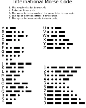
Morse code is one of the simplest and most versatile character encoding scheme used in telecommunication. It encodes text characters as standardized sequences of just two signal durations called dot (·) and dash (-). The dot duration is the basic unit of time measurement in Morse code. The duration of a dash is three times the duration of a dot. Each dot or dash within a character is followed by a period of input absence, called a space, equal to one dot duration. Two adjacent letters in a word are separated by a longer space of duration equal to three dots, and two adjacent words are separated by a space duration of seven dots. Morse code has been developed and used for many languages such as English, Greek, and so on. Figure 1 shows the International Morse Code, which encodes the ISO (International Organization for Standardization) basic Latin alphabet and Arabic-numerals. Morse code can be memorized in a few hours for most people [28] and trained personnel can accurately interpret the signaling of Morse code.
Fig. 1: The International Morse Code.
Morse code can be easily transmitted by any on-off keying of an information carrying medium such as electric current, radio waves, visible light and sound waves. It has been widely used in lots of applications. In aviation, the station usually
transmits a unique set of identification letters in Morse code through radio wave to ensure that the station is available for the pilots. Another application of Morse code in daily life is signaling “SOS” for help with simple three dots, three dashes, and three dots as regulated in international treaties.
Morse code has also been employed to help people with speech and motion impairments to communicate. One big advantage of Morse code is that it requires minimal amount of motion control. It was reported that a shipboard radio operator who had a stroke and lost the ability to speak or write is still able to communicate with his physician through Morse code by blinking his eyes [29]. Recently, Google cooperates with Morse code expert Tania Finlayson to develop Gboard [30], which allows users to input text using Morse Code as an alternative to keypad and handwriting recognition.
B. WiFi Based Finger Gesture Design for Morse Code Input Channel State Information (CSI) is traditionally used to quantify the wireless channel between the transmitter-receiver (Tx-Rx) pair. Compared with Received Signal Strength (RSS), subcarrier-based CSI readings are more sensitive to small movements which result in changes of CSI amplitude and phase. In this work, we carefully design the finger gestures based on the characteristics of Morse code to further reduce the amount of finger movements for MND patients.
As described in Section II-A, the basic elements of Morse code are dot and dash with different time durations. We notice that for a finger to perform the dash operation, the whole hand needs to slightly move horizontally, which is challenging for MND patients. We thus modify the Morse code gesture to avoid hand movement and only require one finger to move up and down. As shown in Figure 2, the finger gesture
down-up corresponds to dot (Figure 2b), while the finger gesture
down-up-down-up corresponds to dash (Figure 2c). Different
from the original Morse code design which separates letters and words by different periods of time that requires longer pause time, we design the up finger gesture (Figure 2a) as
Start and the down finger gesture (Figure 2d) as End. This
design properly utilizes the natural finger actions for users, as the finger movements “up” and “down” correspond directly to the “Start” and “End” operations. With these four basic finger gestures, we can easily input letters, numbers, and punctuation marks using Morse code.
(a) Gesture 1: Start (b) Gesture 2: Dot
(c) Gesture 3: Dash (d) Gesture 4: End
Fig. 2: Finger gesture design for Morse code. (a)up: Start character input, (b)down-up: corresponds to Dot in Morse code, (c)down-up-down-up: corresponds to Dash in Morse code, and (d)down: End character input.
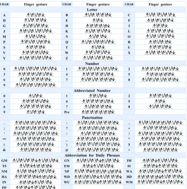
We apply our finger gesture design to encode the ISO basic Latin letters, the Arabic numerals, and a small set of punctuation marks. The full list of designed finger gestures
are shown in Figure 3. To increase the speed of text input, we adopt the following two schemes. First, we employ shorter-length gestures to represent those more frequently used letters. For instance, “E” is the most frequently used letter in En-glish [31] and has the shortest finger gesture in our design: up-down-up-down. Second, frequently-used abbreviations (shown in Figure 3) are applied to accelerate the input speed. For example, “GM” means “Good Morning”. Specifically, for inputting numbers, we also design the short codes with a preamble to start and end inputting numbers.
CHAR Finger gesture CHAR Finger gesture CHAR Finger gesture Letter A _ _ _ _ _ B _ _ _ _ _ _ _ C _ _ _ _ _ _ _ D _ _ _ _ _ _ E _ _ _ _ F _ _ _ _ _ _ _ G _ _ _ _ _ _ H _ _ _ _ _ _ _ I _ _ _ _ _ J _ _ _ _ _ _ _ K _ _ _ _ _ _ L _ _ _ _ _ _ _ M _ _ _ _ _ N _ _ _ _ _ O _ _ _ _ _ _ P _ _ _ _ _ _ _ Q _ _ _ _ _ _ _ R _ _ _ _ _ _ S _ _ _ _ _ _ T _ _ _ _ U _ _ _ _ _ _ V _ _ _ _ _ _ _ W _ _ _ _ _ _ X _ _ _ _ _ _ _ Y _ _ _ _ _ _ _ Z _ _ _ _ _ _ _ Number 0 _ _ _ _ _ _ _ _ 1 _ _ _ _ _ _ _ _ 2 _ _ _ _ _ _ _ _ 3 _ _ _ _ _ _ _ _ 4 _ _ _ _ _ _ _ _ 5 _ _ _ _ _ _ _ _ 6 _ _ _ _ _ _ _ _ 7 _ _ _ _ _ _ _ _ 8 _ _ _ _ _ _ _ _ 9 _ _ _ _ _ _ _ _ Abbreviated Number 0 _ _ _ _ 1 _ _ _ _ _ 2 _ _ _ _ _ _ 3 _ _ _ _ _ _ _ 4 _ _ _ _ _ _ _ _ 5 _ _ _ _ 6 _ _ _ _ _ _ _ _ 7 _ _ _ _ _ _ _ 8 _ _ _ _ _ _ 9 _ _ _ _ _ Pre _ _ _ _ _ _ _ _ _ Punctuation . _ _ _ _ _ _ _ _ _ : _ _ _ _ _ _ _ _ _ , _ _ _ _ _ _ _ _ _ ; _ _ _ _ _ _ _ _ _ ? _ _ _ _ _ _ _ _ _ = _ _ _ _ _ _ _ _ ' _ _ _ _ _ _ _ _ _ / _ _ _ _ _ _ _ _ ! _ _ _ _ _ _ _ _ _ ━ _ _ _ _ _ _ _ _ _ _ _ _ _ _ _ _ _ _ _ " _ _ _ _ _ _ _ _ _ ( _ _ _ _ _ _ _ _ ) _ _ _ _ _ _ _ _ _ $ _ _ _ _ _ _ _ _ _ _ & _ _ _ _ _ _ _ _ @ _ _ _ _ _ _ _ _ _ + _ _ _ _ _ _ _ _
Abbreviation for Daily Phrases
GM _ _ _ _ _ _ _ _ _ _ GN _ _ _ _ _ _ _ _ _ _ IM _ _ _ _ _ _ _ _ _ TS _ _ _ _ _ _ _ _ _ EM _ _ _ _ _ _ _ _ IS _ _ _ _ _ _ _ _ _ _ NM _ _ _ _ _ _ _ _ _ NP _ _ _ _ _ _ _ _ _ _ _ WA _ _ _ _ _ _ _ _ _ _ HA _ _ _ _ _ _ _ _ _ _ _ WD _ _ _ _ _ _ _ _ _ _ _ HD _ _ _ _ _ _ _ _ _ _ _ _ IN _ _ _ _ _ _ _ _ _ WU _ _ _ _ _ _ _ _ _ _ _ WM _ _ _ _ _ _ _ _ _ _ IW _ _ _ _ _ _ _ _ _ _
Fig. 3: Finger gestures for the International Morse code which encodes letters, numbers, punctuations and general-use Morse code abbreviations. Pre: Preamble to start and end inputing numbers, GM: Good Morning, GN: Good Night, IM: I’m/I am, TS: Thanks/Thank you, EM: Excuse Me, IS: I’m Sorry, NM: Never Mind, NP: NO Problem, WA: What are, HA: How are, WD: What do/does, HD: How do/does, IN: I’m not/I don’t understand, WU: Where are you from, WM: What do/does mean, IW: I am/will be with. “↑” and “↓” mean “Start” and “End” finger gestures, while “V” with arrow and “W” with arrow mean “Dot” and “Dash” finger gestures. “ ” means pause between finger gestures.
C. Empirical Study
Now we verify with benchmark experiments the feasibility of recognizing the four basic finger gestures (shown in Fig-ure 2) with WiFi signals from commodity WiFi devices.
1) Experimental Setup: We employ commodity WiFi router
and Gigabyte Mini-PC equipped with the Intel 5300 802.11n Network Interface Card (NIC) to collect CSI readings [32]. The experiments were conducted in an ordinary home environ-ment with a Wi-Fi access point (e.g., TP-Link router) as shown in Figure 4. The user sits in her wheelchair with one WiFi receiver (Mini-PC) placed on the tray table in front of her. The receiver is equipped with two commonly-used vertically polarized antennas and receives packets from the router. The
Rx
Router
Finger
Fig. 4: Experimental setup.
central carrier frequency is set as 5.24GHz. The user performs the four basic finger gestures on the desk surface at different
locations1. We monitor the CSI amplitude variation during the
process. We notice that when there is no finger movement, the CSI amplitude is relatively steady. When a user performs finger gestures, the finger movements result in CSI amplitude variations.
2) Results Analysis: In this subsection, we analyze the
signal variation patterns induced by the finger gestures and identify the practical issues which affect the performance of recognition.
Observation 1: The small signal variation induced by
sub-tle finger movements can be easily buried in noise. As shown
in Figure 5, the finger movement induced signal variation is small while the noise level of the CSI readings is high. When the receiver is close to the transmitter (e.g., 1m), the gesture-induced signal pattern could be (roughly) observed, as shown in Figure 5a. However, when the receiver moves further away from the transmitter (e.g., 2m), the signal pattern can hardly be detected, as shown in Figure 5b.
(a) Close to the transceivers (b) Far from the transceivers
Fig. 5: The signal for gesture “A” (↑ ↓↑ ↓↑↓↑ ↓) is
submerged by noise and not easy to detect, especially when the finger is further away from the transceivers.
Observation 2: The signal pattern for the same finger
gesture is inconsistent at different locations.When the finger is
close to the transceivers, at one particular location, the signal patterns for “Start”, “End”, “Dot” and “Dash” are unique and stable as shown in Figure 6a-6g, which can be accurately identified. However, when we perform these gestures at dif-ferent locations, we observe that the signal patterns for the same gesture are inconsistent. As shown in Figure 6c, the same “Dot” input induces a signal pattern that is dramatically different from that in Figure 6d when the input location is changed.
1Our system does not require the finger to touch a surface, which can be
useful in certain scenarios, e.g., hand hanging from an armrest.
(a) “Start” signal at location 1 (b) “Start” signal at location 2
(c) “Dot” signal at location 1 (d) “Dot” signal at location 2
(e) “Dash” signal at location 1 (f) “Dash” signal at location 2
(g) “End” signal at location 1 (h) “End” signal at location 2 Fig. 6: Signal patterns for the same finger gesture are incon-sistent at different locations (left column vs. right column). D. Challenges
To accurately recognize the fine-grained finger gestures for Morse code input using commodity WiFi devices, we must overcome the following challenges in the design and implementation of our system:
How to detect subtle finger movements accurately amid large hardware and environmental noises? As shown previ-ously, the signal variations introduced by subtle finger move-ments are very small. As such, the finger movement-induced signal variations can be easily buried in noise and become undetectable. To sense such small signal variations with high accuracy, the noise issue need to be carefully addressed.
How to handle the signal pattern inconsistency caused by location difference? To accurately recognize each finger gesture, the signal variation pattern should be consistent for the same gesture at various input locations. And the above consistency should also be maintained for different users without requiring user-specific calibration.
III. WIMORSESYSTEMDESIGN ANDIMPLEMENTATION
In this section, we present in detail how we address the challenges identified in Section II-D. We first propose the use of CSI ratio between two antennas in the same WiFi card, analyze its properties and verify that it provides better signal measurement than the amplitude of CSI. We also propose a
signal transformation mechanism to rectify inconsistent signal patterns due to location variations and verify its effectiveness. Finally, we present the overall design and implementation of WiMorse, a real-time contactless Morse code input system using commodity WiFi devices.
A. CSI Ratio: A Better Base Signal
As noted earlier, commodity WiFi devices have large CSI amplitude noises, which can easily mask the signal induced by fine-grained finger gestures. Therefore, a better base signal is needed in order to adequately capture subtle finger movements. Here, we first give a quick introduction of CSI, then analyze in detail the proposed CSI ratio as a better base signal.
1) Channel State Information: Channel State Information
(CSI) describes properties of a wireless communication link. It characterizes how a signal propagates from the transmitter (Tx) to the receiver (Rx) and captures the combined effects of reflecting, scattering and fading with distance. The complex valued CSI H(f, t) of a carrier with frequency f at time t satisfies the relationship Y (f, t) = H(f, t) × X(f, t), where X(f, t) and Y (f, t) are the frequency domain representa-tions of the transmitted and received signals, respectively. Specifically, a WiFi signal transmits from Tx to Rx through multiple paths, which can be grouped into static paths and dynamic paths[33], [25]. The static paths are composed of the LoS path and reflected paths from the walls and static objects in the environment, which do not change with time. While the dynamic paths are the signal paths induced by the moving targets, we assume there is only one reflection path corresponding to human target’s movement. Furthermore, due to the fact that Tx and Rx are not clock-synchronized, the received CSI can be denoted as:
H(f, t) = e−i·(2π∆f t+θl+θs+θd)(H s(f, t) + Hd(f, t)) = e−i·(2π∆f t+θl+θs+θd)(H s(f, t) + ~a(f, t) · e−i2π d(t) λ ) (1)
where ∆f is Central Frequency Offset (CFO), θl, θs and θd
are phase errors introduced by Phase Locked Loop (PLL), Sampling Frequency Offset (SFO) and Packet Boundary
De-tection (PBD) uncertainty, respectively. Hs(f, t) is the static
path component which is the sum of static paths, while ~a(f, t) is the complex valued representation of attenuation and initial
phase offset of the dynamic path component Hd(f, t) which
varies with dynamic path length d(t). λ is the wavelength for the carrier with frequency f .
The amplitude of CSI |H(f, t)| fluctuates due to phase offsets caused by CFO, PLL, SFO and PBD. Among all the random phase offsets, the CFO phase offset caused by unsynchronized clocks of Tx and Rx has the most serious influence on CSI phase. Due to the frame aggregation mech-anism in 802.11n, commercial WiFi devices can continuously transmit at most 4000 frames per second. Even with the highest transmission rate, the CFO phase offset can be as large as 50π between consecutive CSI values [33]. The PLL phase
offset θl is fixed after the devices are started. The SFO phase
offset θs is caused by the offset of the sampling frequencies
of Tx and Rx [34]. The PBD phase offset is caused by the time shift from the packet boundary uncertainty and follows
a Gaussian distribution with the zero mean. To obtain a clear signal induced by fine-grained finger movements, we need to effectively eliminate these phase offsets.
2) CSI Ratio: Modern WiFi devices that support IEEE
802.11n/ac standards typically consist of multiple transmit-ting and receiving antennas, thus supportransmit-ting Multiple-Input Multiple-Output (MIMO). Since the different antennas in the same WiFi NIC adapter share the same clock, they have the same CFO, PLL, SFO, and PBD phase offsets. This offers us an opportunity to eliminate the influence of various CSI phase offsets. Based on this key observation, we propose the use of CSI ratio between two antennas, which is defined as follows:
QCSI= Hant1(f, t) Hant2(f, t) = Hs1(f, t) + ~a1(f, t) · e −i2πd(t) λ Hs2(f, t) + ~a2(f, t) · e−i2π d(t)+∆d λ (2)
where Hant1(f, t) and Hant2(f, t) are the CSIs received by
two different antennas in the same NIC adapter, respectively.
Hs1(f, t) and Hs2(f, t) are the static path components of these
antennas, while ~a1(f, t) and ~a2(f, t) are the attenuation and
initial phase offsets of the antennas’ dynamic path compo-nents. ∆d is the dynamic path length difference between the two antennas due to their different physical locations. Please note that for a small-scale movement, ∆d can be considered as a constant.
In Equation 2, each part of QCSI is a complex valued
representation. As such, QCSI satisfies the linear fractional
transformation form [35], also referred to as M¨obius
trans-formation, which has the conformal property (i.e., linear fractional transformation can preserve angles and generalized
circles). Based on these properties, we can rewrite QCSI in
Equation 2 as follows:
QCSI= F (z) + ~a (3)
where z = e−i2πd(t)λ , F (◦) is a linear fractional transformation
function, its domain z is a unit circle and its range is also
a circle. ~a is the static component of QCSI and is a
con-stant complex value. When the dynamic path length changes continuously (e.g., due to finger movement), the phase of z also changes continuously. As such, vector z rotates, and F (z) rotates with respect to ~a. F (z) is thus the dynamic component
of QCSI. As illustrated in Figure 7, the green line is the static
component ~a, the (dashed) red line is the dynamic component F (z), and the (dashed) blue line is the combined CSI ratio
QCSI. Given a small-scale movement, QCSIhas roughly fixed
amplitude with varying phase. Then the amplitude of CSI ratio can be calculated as follows:
|QCSI| =p|F (z)|2+ |~a|2+ 2|F (z)||~a| cos α (4)
where α is the phase difference between F (z) and ~a. 3) Understanding CSI Ratio with Benchmark Experiments: As shown in Figure 8, we use a metal plate (the ideal signal reflector) as the moving target to reveal the properties of CSI ratio in a meeting room. The WiFi transceivers are placed 1m apart and the antennas are positioned at 20cm above the table. The transmitter is equipped with one omni-directional antenna
I α Dynamic Component F(z) Combined CSI Ratio QCSI Q Static Component ā
Fig. 7: Vector representation of CSI ratio.
Metal plate 35cm*40cm
Tx Rx
LoS=1m
Sliding track
Fig. 8:Experimental setup to verify CSI ratio. The transceivers are
equipped with Intel 5300 NIC adapter. The size of the metal plate is 35cm × 40cm.
while the receiver is equipped with two omni-directional antennas that are 5cm apart. The metal plate has a size of 35cm ∗ 40cm and moves along the perpendicular bisector of the two transceivers on top of a 1.5m-long sliding track which is controlled by Raspberry Pi 3 Model B. The WiFi signal is transmitted in the 5.24GHz frequency band with a channel bandwidth of 40MHz.
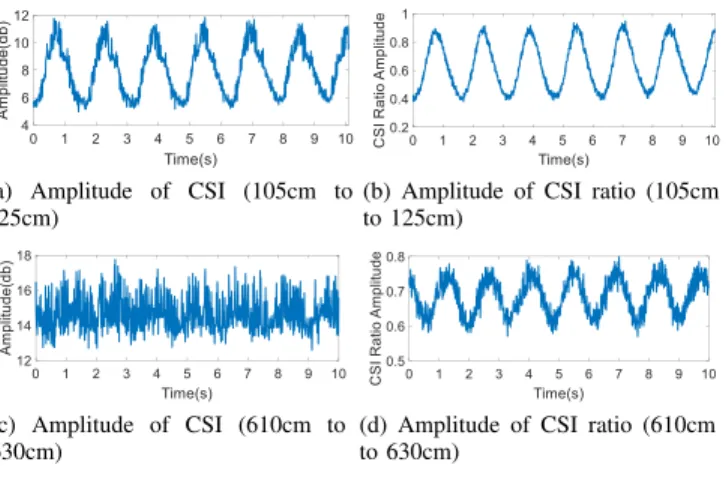
Experiment 1: Verify that the amplitude of CSI ratio is a better base signal. We move the metal plate from 105cm to
125cm2at a speed of 2cm/s. As can be seen in Figure 9a and
Figure 9b, both the amplitude of CSI ratio and the amplitude of CSI show clean patterns. And the amplitude of CSI ratio has smaller noise. When we move the metal plate from 610cm
to 630cm at the same speed, Figure 9c and 9d show the
corresponding raw CSI amplitude and the amplitude of the CSI ratio, respectively. Note that the raw CSI amplitude is noisy and can not identify the target movements from a long distance. Whereas the amplitude of the CSI ratio still shows the periodic variations clearly. Besides, we observe that the phase of raw CSI is random, while the phase of CSI ratio has similar patterns as shown in Figure 9d. In summary, compared with the raw CSI signal, the CSI ratio is a better base signal for capturing fine-grained movements.
Experiment 2: Verify that the dynamic component of CSI ratio rotates with respect to the static component. We move the metal plate from 105cm to 114.4cm away from
2The distance is measured from the metal plate to the LoS path of the
transceiver pair.
(a) Amplitude of CSI (105cm to 125cm)
(b) Amplitude of CSI ratio (105cm to 125cm)
(c) Amplitude of CSI (610cm to 630cm)
(d) Amplitude of CSI ratio (610cm to 630cm)
Fig. 9: Comparison between amplitude of CSI and amplitude of CSI ratio. The latter shows smaller noise and cleaner pattern.
Line of Sight (LoS) at a speed of 2cm/s. According to the vector representation model described in Section III-A2, the dynamic component rotates with the static component. When the dynamic path length changes by λ, the dynamic component
rotates 360◦, corresponding to a complete sinusoidal cycle.
The results are shown in Figure 10 and we can see that the dynamic component generates close to perfect circles, demonstrating the correctness of the property. In Figure 10a, the red dot is the origin of the coordinates. We can see that the dynamic component (red line) rotates clockwise with respect to the static component (green line), and the rotation
phase exactly matches the theoretical rotation phase 1080◦
(3 circles), corresponding to three complete sinusoidal cycles in Figure 10b. Furthermore, the magnitude of the dynamic component remains approximately the same within a short movement distance. In Figure 10b, the blue line is the raw signal, and the red line is the filtered signal (using Savitzky-Golay filter which will be explained in detail in Section III-C).
Static Component ā Dynamic
Component F(z)
Combined CSI Ratio QCSI
(0,0)
(a) I/Q of CSI ratio (b) CSI ratio amplitude
Fig. 10: Verification experiment showing that (a) the dynamic
component (red line) rotates (3 circles) clockwise with respect to the static component; and (b) the amplitude of CSI ratio is a sinusoidal-like wave.
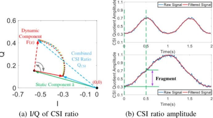
Experiment 3: Verify that fine-grained movements result in signal variations corresponding to a fragment of a si-nusoidal cycle. In this experiment, the metal plate repetitively moves along the sliding track at a small scale (1cm forward and then 1cm backward) to mimic tiny movements of a human body. The initial position is at 51cm from the LoS path. The metal plate performs 2 repetitive cycles of movements. In Figure 11a, we can see that the dynamic component (red line) rotates with respect to the static component (green line) in less than a circle. Therefore, the generated amplitude of CSI
ratio signal in top figure of Figure 11b is a fragment of the complete sinusoidal cycle in bottom figure of Figure 11b.
Static Component ā Dynamic Component F(z) Combined CSI Ratio QCSI (0,0)
(a) I/Q of CSI ratio
Fragment
(b) CSI ratio amplitude
Fig. 11: Verification experiment showing that when the dynamic
path length change is less than λ, (a) the dynamic component (red line) rotates with respect to the static component (green line) in less than a circle; and (b) the amplitude of CSI ratio (Top) induced by fine-grained movement is a fragment of the complete sinusoidal cycle (Bottom).
4) Key Properties of CSI Ratio: Based on the above
ob-servations, we highlight the key properties of CSI ratio as follows:
(1) The amplitude of CSI ratio removes the random phase offsets of CSI signal by using two different antennas in the same NIC adapter, resulting in a better base signal than the amplitude of CSI.
(2) When an object moves along the same direction, the dynamic component of CSI ratio rotates with respect to the static component. As such, the amplitude of CSI ratio shows a continuous sinusoidal-like wave.
(3) The moving object induces path length change of the reflection signal. When the length of the dynamic path changes by λ, the phase of the dynamic component of CSI ratio will change by 2π, generating a complete sinusoidal cycle in the amplitude signal. If the dynamic path length change is less than λ, then the generated CSI ratio amplitude signal represents a fragment of the complete sinusoidal cycle.
B. Signal Transformation: Addressing Inconsistent Pattern due to Location Variation
As discussed in Section III-A, the dynamic component of CSI ratio rotates with respect to the static component and
for fine-grained movements, the rotation is less than a full circle. As a result, the induced amplitude of CSI ratio is only a fragment of the complete sinusoidal cycle. Depending on where the finger is positioned relative to the Tx and Rx, the fragmented cycle will induce different signal patterns. Recognizing each gesture with very different signal patterns is infeasible for practical use. Instead, an automated signal transformation mechanism is needed to convert different signal patterns of the same gesture to one waveform.
1) Signal Pattern Inconsistency: Let’s first analyze why the
same gesture may induce inconsistent signal patterns. Consider for example the “Dot” finger gesture. When the finger moves “down-up”, the ideal signal pattern is shown in Figure 12. Specifically, as illustrated in Figure 13(b), when the finger moves “down”, the dynamic component F (z) rotates from the solid red arrow position to the dashed arrow one, scanning a sector area with angle β; and F (z) rotates back from the dashed arrow position to the solid one when the finger moves “up”. As a result, we observe one valley of the signal for the “Dot” finger gesture.
However, when the finger gesture is performed at different positions, the fragments may be extracted from different parts of the circle, as shown in Figure 13. Essentially, the specific signal pattern is determined by the phase difference α between
the average dynamic component 3 and the static component
~a. When α = 0◦ (Figure 13a), the fragment appears at the
top portion of the circle and the observed signal pattern has two peaks. If the finger is positioned slightly to the right and
α = 90◦(Figure 13b), we can observe the signal pattern with
one valley. If the finger is positioned further to the right, the dynamic component continues to rotate to the right, arriving
at α = 180◦(Figure 13c). Then the observed signal pattern
has two valleys. Finally, when the dynamic component rotates
to α = 270◦, the signal pattern has one peak. This explains
why the same finger movement may induce different signal patterns at different positions.
2) Signal Transformation-Key Idea: Requesting users to
position their fingers precisely at certain locations is incon-venient and even infeasible in real-world usage scenarios. Instead, an automated signal transformation mechanism is essential in order to rectify the inconsistent signal patterns relative to their positions and map them to the true finger
3Since the dynamic component F (z) has a starting point and an ending
point, we use the average of the two points to represent the sector.
Finger gesture
Signal pattern Fig. 12: Ideal signal pattern for the “Dot” finger gesture.
ā QCSI I I (a) (b) (c) F(z) (d) ā QCSI I I ā I I QCSI Signal pattern Vector representation ā I I QCSI O O O O α=0° α=90° α=180° α=270° F(z) F(z) F(z) β β β β
Fig. 13: Inconsistent signal patterns (amplitude of CSI ratio) for the same “Dot” finger gesture at different locations: (a) two peaks, (b) one valley, (c) two valleys, and (d) one peak.
Q
CSIF(z)
ā
β
I
O
Q
α=0°(a) Original IQ vector space
ānew QCSI F(z) ā β η I’ O Q’ ē ρ α=90°
(b) New I’Q’ vector space after transformation
Fig. 14: The key idea of the proposed signal transformation mechanism: (a) Original IQ vector space and (b) New I’Q’ vector space after transformation by introducing a static
com-ponent ~e.
gesture. Intuitively, since the signal pattern inconsistence is caused by the relative position of the dynamic component and the static component in the original IQ space, the key is to identify that relative position and rotate the original IQ space accordingly to match the ideal case. This can be accomplished by introducing a static component that is determined by the initial position of the finger relative to the transceivers.
As illustrated in Figure 14, when a static component ~e is
introduced, the original IQ vector space transforms to the new I’Q’ vector space. When the original static component
is rotated by η phase, from ~a to ~anew, the vector space also
rotates by η phase. We want to choose η such that the signal pattern matches the ideal finger gesture movement in the new vector space, .
3) Signal Transformation-The Design: Based on the
anal-ysis above, we propose an automated signal transformation mechanism to determine the static component to add and trans-form IQ to a new vector space. As illustrated in Figure 14b, we construct a triangle (shown in purple) to calculate the added
static component ~e. Mathematically, the CSI ratio in the new
vector space can be denoted as ˆ
QCSI = F (z) + ~a + ~e (5)
where ~e is the newly-added static component, which is
rep-resented as a complex value. For a given phase shift η, the
amplitude of the added static component ~e can be calculated
using the law of cosines as follows:
|~e| =p|~a|2+ |~a
new|2− 2|~a||~anew| cos η (6)
To obtain the phase of the added static component ~e, we
employ the theorem sin η|~e| = |~anew|
sin ρ . The phase between the
original static component and the added static component ρ is
calculated as arcsinsin η|~anew|
|~e| . Thus the phase of the added
static component is calculated as follows:
θ~e= θ~a+ arcsin
sin η|~anew|
|~e| − π (7)
Given a sequence of original CSI ratio values Q =
{CSI1, CSI2, · · · , CSIL}, the original static component ~a
can be roughly estimated using the average CSI ratio, i.e.,
~a = mean{CSI1, CSI2, · · · , CSIL}. To maintain the
com-parability of the original vector space and the new vector space, we keep the amplitude of the new static component
~anew to be the same as the amplitude of the original static
component ~a, i.e., |~anew| = |~a|.
Now, for a given phase shift η, we can compute the added static component using the formulas above. To determine the
optimal ~e, we utilize a searching scheme to transverse all
possible phase shifts η. Let phase shift η vary from 0 to 2π
with a fixed step size, e.g., 180π , then the phase difference α
also varies between 0 and 2π. For each η, we compute the
corresponding ~e, and use it to transform the CSI ratio signal.
The optimal transformation is obtained when the transformed signal matches the ideal case (e.g., Figure 12 for the “Dot” finger gesture). Since each character begins with the “Start” gesture (Figure 2) and the finger position is relatively stable during the input of each character, we use the ideal signal of the “Start” gesture (referred to as the “reference signal”) to
choose the optimal ~e for signal transformation.
(a) Dot, location 1, original (b) Dot, location 1, transform
(c) Dot, location 2, original (d) Dot, location 2, transform
(e) Dash, location 1, original (f) Dash, location 1, transform
(g) Dash, location 2, original (h) Dash, location 2, transform
Fig. 15:Comparison of CSI ratio amplitude before and after signal
transformation for two different finger gestures (Dot and Dash) at two different locations.
4) Signal Transformation-Verification: To verify the
effec-tiveness of our proposed signal transformation mechanism, we performed two different finger gestures (“Dot” and “Dash”) at different locations. The results are shown in Figure 15. For the “Dot” finger gesture, the original signal pattern at location 1 is not clear (Figure 15a). After transformation, the
Socket
Signal Denoising CSI Ratio
Router WiFi Receiver
Scenario
Real-Time Data Acquisition
Finger Gesture Data Preprocessing CSI Stream Pattern Transformation Transformation in Software
Finger Activity Segmentation
Vector Space Selection
Gesture Identification and Coding Finger Gesture Identification
Morse Code Generation
Output Results
Character Generation
AB… …
A
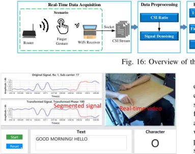
B Fig. 16: Overview of the WiMorse system.
Real-time video Segmented signal
Fig. 17: The web-based user interface for WiMorse: (Top-left) original and transformed signals (amplitudes of CSI ratio); (Top-right) real-time video of finger gestures.
down-upsignal pattern becomes clear in the new vector space
(Figure 15b). For location 2, the original signal pattern of the “Dot” finger gesture was flipped (Figure 15c), and our transformation mechanism can also correct it to the right signal pattern down-up(Figure 15d). For the “Dash” finger gesture, the transformation mechanism also worked well, correcting inconsistent signal patterns in Figure 15e and Figure 15g into the right signal patterns in Figure 15f and Figure 15h, respectively.
C. System Implementation
Figure 16 gives an overview of the WiMorse system, which consists of four core modules: (1) real-time data acquisition, (2) data preprocessing, (3) pattern transformation, and (4) gesture identification and decoding. We have also developed a web-based user interface to show the signals, text input along with real-time video as shown in Figure 17. A real-time demo video is provided together with this manuscript and also at
link: https://youtu.be/xGOdSJS2dWk.
Real-time data acquisition. In WiMorse, the transmitter is a wireless Access Point (AP), e.g., a router or a laptop. The receiver can be a smart device, e.g., a laptop or a mobile phone. In our system implementation, we employ a TP-Link router as transmitter and one Gigabyte MiniPC equipped with Intel 5300 NIC adapter as the receiver. The receiver is equipped with two omni-directional antennas (5cm apart) for the purpose of obtaining CSI ratio. The antennas run on the 5.24GHz channel with a 40MHz channel bandwidth in an IEEE 802.11n WiFi network. When using the system, the MiniPC continuously receives wireless packets from the router. These packets are sampled at the receiver side to extract CSI values. We collect CSI readings from the WiFi adapter using the CSI-tools [32]. The packet transmission rate is 100 packets per second. A Dell laptop (Precision 5520) with Xeon CPU and 16G RAM is connected to the receiver via an Ethernet cable to collect CSI packet samples (20 packets every 0.2s) and process the data in real time.
Data preprocessing. From each sampled packet, we can obtain two CSI streams simultaneously (one from each re-ceiving antenna) to calculate CSI ratio. To refine the CSI stream for fine-grained finger gesture recognition, WiMorse first denoises the raw amplitude of the CSI ratio signal using a least-square smoothing filter named Savitzky-Golay filter, which fits successive subset of adjacent data points with a polynomial by the linear least square method [36]. Figure 15 shows the raw CSI ratio amplitude signal (blue line) and the smoothed signal after applying the filter (red line). We can see that the filter effectively removes the small random variations while maintaining the large signal variations caused by finger movements.
1 2 3 4 5
pause finger gesture
Fig. 18: Determining the starting and ending time points of each finger gesture. The top figure shows the signal of finger gestures, while the bottom figure shows the amplitude difference and threshold for segmenting the finger gestures.
Pattern transformation. As mentioned in Section III-B, the signal patterns are inconsistent when performing the same finger gesture at different locations, and we propose a sig-nal transformation mechanism to convert the sigsig-nal patterns at different locations to one waveform. To segment finger gestures in the character after transformation, we detect the pause between consecutive finger gestures by leveraging the variance of CSI ratio amplitude, which is very sensitive to subtle movements. As shown in Figure 18, the top subfigure shows amplitude of CSI ratio for finger gestures of character “G”, while the bottom subfigure shows the difference between the maximum and minimum amplitude of the CSI ratio signal
in each 0.7s sliding window with a step size of 0.35s 4. As
we can see in the figure, the difference between the maximum and minimum amplitude within the pause period is very small. We thus employ a threshold-based method to detect the pause
4The window size and step size are carefully selected to capture individual
and accordingly segment the finger gestures. The threshold is set to 0.045 in our experiments, and is denoted as the horizontal red line in the bottom subfigure of Figure 18. The state transition of the movements is utilized as a parameter to identify the starting and ending points of the finger gestures, shown by the purple circled numbers and arrows in Figure 18. Specifically, the first finger gesture (purple circled number 1) and the last finger gesture (purple circled number 5) are the “Start” finger gesture and “End” finger gesture to segment characters, respectively. The second and third finger gestures are “Dash” finger gestures in character “G”, while the fourth finger gesture is “Dot” finger gesture.
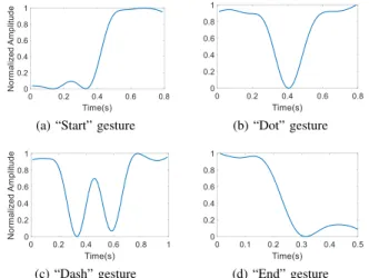
Based on the observation that the optimal vector space of one finger gesture should work for all finger gestures performed at the same location, we employ the “Start” finger gesture as the reference gesture to compute the optimal static vector to add for signal transformation. The “Start” gesture is the first gesture for each character, so the optimal vector space for the “Start” gesture can be used by other finger gestures in the same character at the same location. By comparing the segmented signal with the reference signal of the “Start” gesture (Figure 19a), the optimal vector space can be determined. To unify the signal patterns, both the segmented signal and the reference signal are normalized to the range of 0 to 1.
(a) “Start” gesture (b) “Dot” gesture
(c) “Dash” gesture (d) “End” gesture
Fig. 19: Signal patterns for four different finger gestures. (a)
up signal pattern for the “Start” gesture, (b) down-up signal
pattern for the “Dot” gesture, (c) down-up-down-up signal pattern for the “Dash” gesture, and (d)down signal pattern for the “End” gesture.
Gesture identification and decoding. Using the proposed signal transformation mechanism, we can guarantee that (1) the same finger gestures performed at different locations have a consistent signal pattern; and (2) different finger gestures performed at the same location have unique signal patterns. In WiMorse, the segmented signal for each finger gesture is first normalized to the range of 0 to 1. We then employ the DTW (Dynamic Time Warping) algorithm to calculate the similarity between the normalized segmented signal and the normalized reference signals (some examples are shown in Figure 19). The best-matching (i.e., highest similarity) reference signal pattern is selected as the finger gesture performed. If the finger
gesture is the “Start” gesture, then Morse code encoding is started. For the “Dot” and “Dash” finger gestures, they are encoded to Morse code, respectively. When the “End” finger gesture is detected, the cumulative Morse code is mapped to the corresponding input character.
IV. EVALUATION
To evaluate the performance of WiMorse, we have imple-mented the real-time Morse code input system using com-modity WiFi devices and conducted comprehensive experi-ments to demonstrate the capability of WiMorse in various environments with multiple participants. In this section, we first present the experimental setup, then report the overall performance and discuss the factors that may impact the performance of WiMorse.
A. Experimental Setup
We have conducted experiments in three practical scenarios: home, office, and meeting room, as shown in Figure 20. We have recruited seven volunteers (one female and six male) to perform the Morse code finger gestures for all the 54 characters (26 letters, 10 numbers, and 18 punctuations). Each volunteer performed each finger gesture 9 times, resulting in 63 instances for each finger gesture and 3402 instances in total. We also generated 30 daily expressions with varying
length sentences5, and each user chose 5 sentences to input.
WiMorse captures the CSI streams in real time and decodes them into corresponding Morse code text.
(a) Home (b) Office (c) Meeting room
Fig. 20: Three different experimental environments. (a) The home has a size of about 4m × 6m with two sofas, one table and a Tv. (b)The office has a size of 4m × 4.5m with one sofa, two tables and one bookcase. (c) The meeting room has a size of 5.1m × 6.9m with three tables and several chairs.
We use the following metrics to evaluate the performance of WiMorse:
Recognition accuracy is the percentage of basic finger gestures (Start, Dot, Dash, and End) or characters that are correctly identified by our system.
Input speed is the Morse code text input speed, which can be measured as Characters Per Minute (CPM) and Words Per
Minute(WPM). Since characters vary by length (i.e., numbers
of dots and dashes), we present statistics on the mean time and time distribution when users input sentences. Words also vary in length, even when they contain the same number of characters. Following previous practice [37], we employ two methods to calculate WPM. The first method assumes that all
5The daily expressions were generated using website https://www.fluentu.
characters occur with the same probability in each word and WPM is calculated as follows: W P M1= S T × 60 × 1 Navg (8) where S is the length of all characters and T is the time in seconds to finish inputting all the characters. 60 refers to the
number of seconds in a minute. Navgis the average length of a
word, and is typically set to 5. In reality, different characters occur with different probabilities in each word. Taking this into consideration, we consider the length of each character to be approximately inverse to the frequency of that character occurring in English text. Then WPM is computed as follows:
W P M2= 60 P c∈CpcTc × 1 Navg (9)
where C is the set of all characters, pc is the probability of
character c(c ∈ C) occurring in English text, and Tcis the time
duration in seconds to enter character c. Navg is the average
length of a word, and is typically set to 5. B. Overall Performance
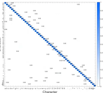
Character recognition accuracy. Figure 21 shows the recognition accuracy for all letters before and after signal transformation. We can see that WiMorse achieves high ac-curacy for all letters, and our proposed signal transformation mechanism significantly improves the recognition accuracy from 48% to 96.6%. Furthermore, Figure 22 shows the confusion matrix for all 54 characters, where the dark blue color indicates higher recognition accuracy while the white color means (close to) zero misclassification. We observe that WiMorse achieves an overall recognition accuracy of more than 95% with a standard deviation of around 2%.
Fig. 21: Recognition accuracy for letters.
Gesture recognition accuracy. Since each character is entered using a combination of the four basic finger gestures (Start, Dot, Dash, and End), we also evaluate the recognition accuracy of these basic gestures. Figure 23 shows the con-fusion matrix of the four basic finger gestures. We can see that WiMorse performs well for all four basic finger gestures, achieving 99%, 98%, 96%, and 99% recognition accuracy for Start, Dot, Dash, and End, respectively.
Effectiveness of CSI ratio and signal transformation. WiMorse has two key design innovations: CSI ratio and signal transformation. To evaluate the effectiveness of each mechanism, we compare WiMorse with two baseline methods: (1) amplitude of CSI, which directly uses the amplitude of CSI as the base signal; and (2) amplitude of CSI ratio, which uses the proposed amplitude of CSI ratio as the base signal but does not use the proposed signal transformation mechanism.
Fig. 22: Confusion matrix showing high average accuracy per character and low misclassification rates.
Gesture Start Dot Dash End Start 0.99 0.01 0 0 Dot 0.01 0.98 0.01 0 Dash 0 0.02 0.96 0.02 End 0 0 0.01 0.99
Fig. 23: Confusion matrix of four basic finger gestures.
Fig. 24: Comparison of ges-ture recognition accuracy using different methods.
Figure 24 compares the recognition accuracy of the four basic finger gestures using each of the three methods. We see that each method performs consistently across all four gestures. The amplitude of CSI method achieves the lowest recognition accuracy (18%), which is improved to 34% when using the
amplitude of CSI ratiomethod, while WiMorse achieves more
than 96% accuracy. These results demonstrate the effectiveness of both CSI ratio and signal transformation, as proposed in Section III.
Recognition accuracy in sentences. To evaluate WiMorse in real-world sentences input, we collected CSI data for six different sentences from previous literatures [38], [39]: S1 = “the quick brown fox jumps over the lazy dog”, S2 = “nobody knew why the candles blew out”, S3 = “the autumn leaves look like golden snow”, S4 = “nothing is as profound as the imagination”, S5 = “my small pet mouse escaped from his cage” and S6 = “the most profound technologies are those that disappear”. Each sentence is typed 3 times without spaces. As shown in Figure 25, WiMorse achieves an average character recognition accuracy is 94.66% in continuously typed sentences. Thus, we conclude that there is no significant difference in character recognition accuracy between character input and sentence input.
Text input speed. To evaluate the speed of continuous text input using WiMorse, we collected CSI values for the daily expressions performed by different users as described in Section IV-A. Figure 26a shows the min, average, and
Fig. 25: Character recognition for different sentences. max input time for each individual character across different users. Figure 26b shows the text input speed for words when considering different metrics (W P M 1 using equal character probability and W P M 2 using statistical probability) and Abbr. that leverages abbreviations (e.g., input “GM” for “Good morning”) and is measured using W P M 2. As shown in the figure, the word input speed is only 1.38 WPM when using the W P M 1 metric and 2.3 WPM when using the W P M 2 metric. WiMorse also supports abbreviations for common phrases, which further increases the word input speed to 2.94 WPM.
(a) Character input speed (b) Word input speed
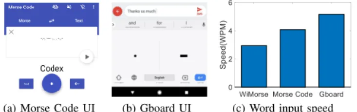
Fig. 26: Text input speed for characters and words. We also compare the input speed of WiMorse with existing Morse code based input systems hosted on mobile devices (e.g., mobile phone and tablet). Two popular systems are selected: Morse Code APP and Gboard. As shown in Fig-ure 27, Morse Code APP (FigFig-ure 27a) employs only one button to input dot and dash with different press time in Morse code, and another button to input space. Figure 27b shows the user interface of Gboard developed by Google, which employs one dot button and one dash button to input dot and dash in Morse code. Figure 27c shows the speed of Morse Code APP and Gboard are 4.07 and 5.16 words per minute, respectively. Note that both these systems require the users to slightly move their hands. On the other hand, the MND patients have difficulties moving their hands. Without a need of hand movement, WiMorse is able to achieve 2.94 WPM for MND patients.
(a) Morse Code UI (b) Gboard UI (c) Word input speed
Fig. 27: Speed comparison with other Morse code input systems.
C. Factors Impacting the WiMorse System Performance In real-world usage scenarios, the performance of WiMorse may be impacted by multiple factors such as location, user di-versity, environments, and other factors. Therefore, we conduct
various experiments to evaluate the impact of these factors on WiMorse.
Impact of location. Figure 28 shows the character recog-nition accuracy at six different locations (Figure 28a) before and after applying the proposed signal transformation mecha-nism. We observe that WiMorse can achieve high recognition accuracy at all six locations. Furthermore, using the original CSI ratio (before transformation) resulted in different recog-nition accuracies at different locations (varying from 38% to 78%), because the original CSI ratio induces inconsistent signal patterns at different locations. However, our proposed signal transformation mechanism can effectively address such location-dependency and improve the character recognition ac-curacy from 49.7% to 94.1%, nearly doubling the recognition performance.
❶ ❷ ❸ ❹ ❺ ❻
Table
(a) Experiments at six different locations
(b) Character recognition ac-curacy by location
Fig. 28: Impact of location on character accuracy and effec-tiveness of WiMorse in addressing such location dependency. Impact of user diversity. As mentioned earlier, we have recruited seven volunteers to perform all the characters (9 times by each volunteer to get 63 instances per character). Based on our results, there is no obvious difference among the character recognition accuracies for different volunteers. However, the users do vary in terms of text input speed. As shown in Figure 29a, volunteer 1 has the highest input speed, since he knows Morse code and has a bit more experience inputting Morse code than others. For other volunteers, the speed is more than 1.6 WPM without any training, and Morse code can be memorized through training, resulting in higher input speed.
Impact of environment. Figure 29b shows the character recognition accuracy in three different environments including home, office, and meeting room. While the environments are different in terms of layouts and setup, WiMorse is able to achieve similarly high accuracy across all three environments, ranging between 92% and 96%. This indicates that WiMorse is robust against environments.
Impact of LoS and height. We also evaluate the impact of LoS and the height of transceivers on the performance of WiMorse. Figure 29c shows the character recognition accuracy under different LoS distances. We see that the accuracy dropped slightly when LoS increases from 1m to 1.5m, and there is a bigger drop when LoS is set to 2m. Figure 29d shows the character recognition accuracy when the transceivers are positioned at different heights above the table. Again, the performance dropped slighted when the height increases from 20cm to 30cm, and there is a bigger drop when the height is set to 40cm. These results indicate that smaller LoS and height are needed to detect fine-grained finger gestures.
(a) Impact of user diversity (b) Impact of environment
(c) Impact of LoS (d) Impact of height
Fig. 29: Evaluation of different impact factors for the WiMorse system.
D. Discussion
In this paper, we have designed WiMorse, a WiFi-based contactless text input system using Morse code for MND patients, which requires only subtle movement of a single finger. Our evaluations show that WiMorse is able to detect fine-grained finger gestures with high accuracy under various environments and with multiple participants. Still, there are several practical issues which need to be addressed in our future work.
Interference from surrounding people. In real-world us-age scenarios, there may be other people in the surrounding area, which introduces interference for WiFi sensing. Note that the received signal is affected by the target and sur-rounding objects. Thus, whether the finger movements can be sensed depends on the signal noise ratio (SNR), which means the surrounding objects’ distance and their motion displacements are not comparable with target movement we are interested. We observe that the interference caused by surrounding people’s movements is quite limited if the target is close to the transceiver pair. Our experimental results show that surrounding interference is minimum beyond a distance of 1.5m, which is reasonable for MND patients.
Leveraging surrounding WiFi devices. Although the pro-posed use of CSI ratio significantly improves the signal noise ratio, fine-grained finger movement can not be well sensed when the transceiver pair is placed far apart. Our experiments show that the performance drops when the LoS is longer than 2m or the height is above 40cm. Thus a dedicated pair of WiFi devices are needed to support the application. Actually the proposed approach can be applied to a 4/5G enabled mobile device with two antennas, where only the device needs to be placed near user’s hands to achieve the goal of WiMorse.
V. RELATEDWORK
The research problem and methodologies presented in this paper are closely related to the following three research areas: traditional text input methods, text input for people with disabilities, and WiFi based fine-grained activity sensing.
Traditional text input methods: Traditional text input is usually based on either typing or handwriting. For typing-based text input, users type on a real or virtual keyboard, and the keyboard allows users to type in letters and digits [40], [41], [42]. For handwriting-based text input, users utilize a pen or touch interface to input text [43], [44]. The recent work RF-Copybook proposes a Chinese calligraphy recognition sys-tem [45]. Using two RFID tags attached to the brush pen and three antennas equipped at the RFID reader, RF-Copybook can track the pen’s movement and monitor the handwriting process. These text input methods described above typically require users to move their hands and arms, which are not feasible for patients with MND.
Text input for people with disabilities: For people who cannot speak or write, they could still communicate through Morse code by blinking their eyes or moving their heads [46]. However, vision-based eyeball tracking systems are usually complex and expensive and the head tracking method works with an extra head touch sensor. When inputting text, patients
are required to shake their heads left or right all the time 6.
SpeechTexter [47] is a voice-based text input system developed to type with voice. However, the recognition accuracy is not high enough, and people with MND will lose their speech function eventually. Meanwhile, Google brings Morse code to Gboard [30], which uses two buttons: a dot “.” and a dash “−” on the phone and allows users to customize the keyboard to their unique input needs. Besides requiring the operation of a mobile phone, constantly shifting finger between the two buttons and touching the screen may be cumbersome and even infeasible for MND patients. A promising approach for MND patients is contactless text input, which does not require patients to carry or wear any device. To facilitate text input for people with MND, this paper proposes Morse code based text input via contactless WiFi sensing, which exhibits clear advantages in terms of cost and the amount of finger motion required.
WiFi based fine-grained activities sensing: With the avail-ability of CSI readings from commodity WiFi devices [32], significant progresses have been made for contactless sensing, enabling new fine-grained activity sensing applications such as keystroke identification [48], hand gesture recognition [20], [21], [49], [50], vital sign monitoring [51], [52], [53], [24], [25], [54], [55], and speaking tracking [56]. For non-periodical activity recognition, WiHear was developed as a lip-reading system that uses WiFi CSI to recognize lip movements, which requires directional antennas and is very sensitive to environment changes [56]. WiKey utilizes WiFi CSI readings to recognize finger keystrokes, while WiSee is a gesture recog-nition system that exploits the Doppler shift in narrow bands extracted from wide-band OFDM transmissions to recognize nine human gestures [57]. WiFinger aims to recognize finger gestures (e.g., digits 1−9 in ASL or specific eight finger gestures) using WiFi signals [20], [22]. Due to the location dependency issue, these activity recognition systems need to fix the positions of the transceivers and can only recognize the activities under the same setting when training data are