an author's https://oatao.univ-toulouse.fr/27090
https://doi.org/10.1109/MAES.2017.160079
Baldi, M. and Bertinelli, M. and Chiaraluce, F. and Closas, P. and Dhakal, P. and Garello, R. and Maturo, N. and Navarro, M. and Palomo, J. M. and Paolini, E. and Pfletschinger, S. and Silva, P. F. and Simone, L. and Vilà-Valls, Jordi State-of-the-art space mission telecommand receivers. (2017) IEEE Aerospace and Electronic Systems Magazine, 32 (6). 4-15. ISSN 0885-8985
INTRODUCTION
Since their dawning, space communications have been among the strongest driving applications for the development of error cor-recting codes [1]–[3]. Indeed, space-to-Earth telemetry (TM) links have extensively exploited advanced coding schemes, from convo-lutional codes to Reed-Solomon codes (also in concatenated form) and, more recently, from turbo codes to low-density parity-check (LDPC) codes. The efficiency of these schemes has been exten-sively proved in several papers and reports.
The situation is a bit different for Earth-to-space telecommand (TC) links. Space TCs must reliably convey control information as well as software patches from Earth control centers to scientific payload instruments and engineering equipment onboard (O/B) spacecraft. The success of a mission may be compromised because of an error corrupting a TC message: a detected error causing no execution or, even worse, an undetected error causing a wrong ex-ecution. This imposes strict constraints on the maximum accept-able detected and undetected error rates.
Space TC links have peculiar characteristics, which are chal-lenging for designers:2
C The complexity is highly asymmetrical: TC messages are
originated on ground (with mild complexity constraints) and received O/B, where resources are very limited.
C Links are asynchronous and bursty: messages are
transmit-ted sporadically and a proper procedure must be adoptransmit-ted to detect them prior to decoding.
C Reliability is a key issue, even more for emergency commands,
that may require a codeword error rate (CER) as low as 10−5
and an undetected codeword error rate (UCER) as low as 10−9.
1 Affiliations and addresses for all the authors appear on page 15. 2 It is interesting to note that some of these features are in common with
new, completely different applications, like ultra-low latency high-reli-ability 5G scenarios.
C Short codes are needed since some commands, e.g.,
emer-gency ones, are very short (2 bytes, typically) and must be received with limited latency. This problem is exemplified by a tumbling spacecraft in deep-space (DS), operating in very low power regime and providing limited availability of the link: in such a case, the command must be received within a short time window.
C DS links are typically characterized by low data-rates, from
few kilobits per second down to tens of bits per second (bps), due to link budget constraints: bandwidth and transmitted power from ground are not a key issue, but the distance to be covered is very long and the received power is limited.
C The challenging channel conditions, due to high Doppler
dynamics and low signal-to-noise ratio (SNR), impose seri-ous constraints on the receiver implementation, pushing the synchronization sub-systems to their limits.
So far, the TC link requirements have been satisfied by com-bining sufficient power transmitted from ground with traditional coding techniques, offering overall marginal coding gains but good error detection capabilities. To do this, typically, the error correc-tion capability of the coding schemes is exploited first, then error detection is applied to check if some residual error still remains. In this case the message is rejected, to heavily reduce the possibility of accepting a wrong command.
NEW REQUIREMENTS AND THEIR IMPLICATIONS
In very recent years, TC links for new missions have evolved toward more and more demanding requirements, whose fulfill-ment necessarily imposes the adoption of error correcting codes approaching the limits of communication channels. The TC link range is becoming huge, reaching hundreds of millions of kilo-meters for DS missions. This becomes a problem due to the lim-ited O/B resources, potentially resulting in operation at extremely low SNR. Missions based on small landers (e.g., rovers) on distant planets are typical examples: given their constraints (e.g., small antennas), signals are received with low SNR values. In general, it is very difficult to command such units directly from Earth without relying instead on an orbiter around the planet, which might share similar SNR issues. Furthermore, next generation mission uplinks, especially near-Earth (NE) ones, will require very high data-rates, Corresponding author's address: Marco Baldi, Dipartimento
di Ingegneria dell'Informazione, Università Politecnica delle Marche, Via Brecce Bianche, 12, Ancona, 60131 Italy, E-mail: ([email protected]).
Review handled by H. Liu.
Feature Article:
State-of-the-Art Space Mission Telecommand
Receivers
M. Baldi, M. Bertinelli, F. Chiaraluce, P. Closas, P. Dhakal, R. Garello, N. Maturo, M.
potentially in the order of several Mbps; even some short-term missions are foreseen with demanding uplink rates that impose se-rious constraints on the O/B architectures.
These new requirements have a strong impact on the TC link design. The need to increase further the coverage and/or the uplink data-rate is at the basis of the next generation uplink (NGU) initia-tive [4], promoted by the Consultadata-rate is at the basis of the next generation uplink (NGU) initia-tive Committee for Space Data Systems (CCSDS). The NGU goal is to define improvements to the existing TC recommendations [5], [6] in order to comply with new missions' requirements.
OBJECTIVES OF THE STUDY
The challenges highlighted in the previous subsection have been addressed by the Next Generation Uplink Coding Techniques (NEXCODE) study, funded under the Technology Research Pro-gramme of the European Space Agency (ESA), which aimed at research, design, development, and demonstration of a TC receiver chain for scientific missions, including new channel codes. Among the objectives of the study, we can mention:
C Introduce, evaluate, and optimize advanced co/decoding
techniques to significantly improve the uplink performances (in terms of data-rate and/or maximum distances) of NE and DS science missions, compared to the currently used code.
C Evaluate and clarify the impact of the new codes in terms of:
Required protocol modifications (if any);
O/B receiver algorithms (acquisition and tracking of up-link signals at lower SNR, determined by higher coding gains);
O/B receiver architecture (to cope with extra complexity and/or new algorithms).
C Prototype the O/B receiver chain core elements, including
the decoder for the advanced coding schemes, by means of commercial off-the-shelf hardware (HW), such as field pro-grammable gate array (FPGA) platforms, to help validating the approach and minimize the risk of adoption, bringing the technology readiness level up to 3–4.
C Evaluate the most relevant metrics, including the effective
coding gains, and the performance/complexity trade-off.
This article describes the main results of the study, by fo-cusing on simulation activities and identification of the main changes required to adopt the new coding options. The study is focused on the short binary LDPC codes that have been recently selected for updating the current TC synchronization and chan-nel coding standard. The new and old codes are introduced in the next section, accompanied by a brief description of the TC data protocol. Then, the subsequent section presents a reference receiver block diagram to contextualize the contribution of this work and discusses its main functionalities and how the inclusion of the new codes might impact its performance. A more detailed analysis of the new codes is presented in a subsection specifi-cally devoted to codes evaluation and optimization. The article concludes providing a discussion on implementation aspects and breadboard prototyping.
SPACE TC LINK STANDARD AND ITS EVOLUTION
The only error correcting code currently included in the CCSDS recommendation [5] and the European Cooperation for Space Standardization standard [6] for TC synchronization and chan-nel coding is a Bose-Chaudhuri-Hocquenghem (BCH) code with length n = 63 bits and dimension k = 56 bits. This BCH code accommodated well the short command sequences, low data-rate transmissions, and decoding simplicity requirements that characterized the demands of TC control links in the past. The increasing demands for transmitting higher data volumes to the spacecraft, coupled with the need of guaranteeing short command-based emergency communications at maximum power efficiency has led to propose new codes for future standardiza-tion of TC protocols.
Agencies and researchers investigated and compared a num-ber of possible alternatives, including binary [7] and nonbinary LDPC codes [8], extended BCH codes [9], and parallel concat-enated turbo codes [10], [11], even in the presence of jamming [12], [13]. The schemes were evaluated taking into account the peculiar characteristics of TC links in terms of coding gain and complexity. At the end of the process, CCSDS chose two short binary LDPC(n, k) codes, namely the LDPC(128, 64) and the LDPC(512, 256) [14]. These codes have been selected in order to meet such needs: with reference to the new standard qual-ity service requirements of CER = 10−5 and UCER = 10−9, they
BCH(63, 56) code [14]. Note that for TC, reliability is driven not only by the CER but also by the UCER, since executing an erroneous command can have disastrous consequences for a mission. Code parameters are contrasted in Table 1 for both cod-ing schemes.
Given the implications of the data structure in the receiver functionality, a general description of the current configuration of the TC link transmission unit, i.e., the Communication Link
Trans-mission Unit (CLTU), is shown in Figure 1.
Commands from Earth to space are sent in the payload of TC transfer frames (TFs). A TF is divided into blocks, each as long as 56 bits and individually BCH encoded. Padding may be used in the last block. A “0” bit (filler bit) is appended to each of the BCH codewords which are then encapsulated between a 16-bit start sequence and a 64-bit tail sequence (Recently the tail sequence
length has been extended to 128 bits.) to obtain the CLTU. The
role of the start sequence is to enable frame synchronization, so that the decoding process can be initiated. On the contrary, the goal of the tail sequence is to allow the decoder for implicitly detecting the end of the CLTU. Preceding the start sequence there is an ac-quisition sequence of alternating “0” and “1” (starting with either a “0” or a “1”) of variable length that serves the purpose of signal acquisition and aids in locking timing synchronization loop. Idle sequences can also be found between CLTUs to help maintaining symbol synchronization. The TC transmission protocol includes an additional mechanism that guarantees a minimum number of sym-bol transitions to keep symsym-bol synchronization. Namely, it applies data randomization by XOR-ing TF data with a pseudorandom se-quence. The randomizer, optional for the BCH code, is mandatory for LDPC codes.
Figure 1.
CLTU data structure.
Figure 2.
High-level functional block diagram for the current CCSDS synchronization and channel coding sublayer data generation.
Table 1.
Adopted Channel Coding Schemes for TC Communications
Parameter BCH(63, 56)
LDPC(128, 64) LDPC(512, 256)
Code rate 0.89 0.5
Message size (bits) 56 64 or 256
Codeword size (bits) 64 (63 + 1 filler bit) 128 or 512
Baldi et al.
Figure 2 depicts the transmitter functional block diagram for CLTU generation (with BCH encoding). TF segmentation includes stuffing of the Mth block, if needed. Note that although the stan-dard allows for more than one TF per CLTU, known missions to date transmit a single TF per CLTU [4]. This has been the assump-tion within NEXCODE.
Figures 1 and 2 can be easily adjusted for including the new codes by replacing the BCH code with the LDPC codes and mod-ifying accordingly the size of the message block and the result-ing codeword. The filler bit is no longer necessary. Moreover, as we will show in the next section, the length of the start sequence should be increased, to compensate the impact of the potential op-eration at a reduced SNR.
Following the CLTU generation, the symbols are modulated onto radio waveforms according to the physical layer operation procedures (PLOP). Among them, the most relevant procedure is PLOP-2 (PLOP-1 remains as support for legacy missions launched
before 2010) where the physical channel is activated for the whole communication session until the last CLTU is received. PLOP-2 invokes the carrier modulation modes (CMM) described in Table 2. Starting at CMM1 the sequence is depicted in Figure 3 (the insertion of the idle sequence is optional—and therefore it is plotted in dashed line).
NEXT GENERATION RECEIVERS FOR SPACE TC LINKS
In the following, we will show that the new LDPC codes allow achieving significant coding gains with respect to the current BCH code. A direct consequence of the performance gains intro-duced by the new codes is the impact on the receiver operating point. Namely, to fully exploit the potential of the new codes, receiver stages previous to decoding are required to operate at a lower SNR. This new requirement might be problematic since those receiver stages were designed for much higher SNRs. We focus on receiver baseband functional blocks, typically imple-mented in the digital domain of the O/B transponder. Standard receiver functionalities can be classified in the following high-level stages:
C signal detection and acquisition, C signal tracking and demodulation, C frame synchronization, and C channel decoding.
Figure 4 provides a block diagram of a generic TC receiver, taking inputs from the analog-to-digital converter interfacing the baseband receiver with the radio frequency (RF) front-end operating at some intermediate frequency (IF). At a glance, the operation of a receiver involves: i) deciding whether a TC signal is present at the receiver (signal detection); ii) comput-ing rough estimates of the signal parameters, such as Doppler frequency, to lock the signal (signal acquisition); iii) tracking the signal and demodulating the symbols (signal tracking and demodulation); iv) detecting, from the stream of noisy sym-bols, the CLTU start (frame synchronization); v) decoding the transmitted TF message (decoding); vi) detecting the CLTU end (termination).
In the following subsections, the impact of the new codes on the various blocks is discussed, as well as their typical implemen-tations with some enhancements proposed when possible.
Figure 3.
PLOP-2 CMM sequence with recommended insertion of idle sequence between CLTUs (see [6, Figure 9.1] for a more detailed description).
Figure 4.
High-level baseband receiver block diagram.
Table 2.
Carrier Modulation Modes
Carrier Modulation Mode
Description
CMM1 Unmodulated carrier only (no data modulation, only RF carrier) CMM2 Carrier modulated with acquisition
sequence
CMM3 Carrier modulated with CLTU
ACQUISITION AND TRACKING
Signal acquisition and tracking will potentially operate at SNRs lower than those currently expected, and this, depending on the configuration, may prove extremely challenging. Identification of receiver processing bottlenecks is done for DS and NE mis-sions. Whereas the former is representative of very low SNR sce-narios, the latter is representative of high data-rates scenarios. In both cases, residual carrier modulation is typically used for the TC link. For NE missions, the transponder is configured to receive a Manchester encoded data phase modulated onto the carrier modulation, a scheme referred to as PCM SP-L [15]. On the other hand, in DS missions the transponder is configured to receive nonreturn-to-zero (NRZ) data modulated on a sinusoi-dal-wave subcarrier that is then phase modulated onto the car-rier (PCM NRZ-L modulation [15]). Representative modulation parameters for the two scenarios are reported in Table 3. For the DS case, the symbol rate used is the minimum one allowed by the standard [15], providing the most demanding scenario for acqui-sition and tracking, i.e. the lowest SNR.
From a receiver perspective, the architecture is similar for both scenarios in Table 3, with the main difference that PCM SP-L does not require subcarrier tracking. Therefore, in tracking mode, the main modules in the receiver are: a carrier tracking block, typically implemented by a phase-locked loop (PLL); a subcarrier tracking block when necessary, typically implement-ed as a Costas loop; and a symbol timing tracking, implementimplement-ed as a data transition tracking loop (DTTL). The data transition detector in the DTTL has to be slightly adapted depending on the encoding type, but its operation is basically the same. These three tracking loops initiate their operation after the signal has been detected and acquired, process referred to as “acquisition mode”.
In acquisition mode, the TC standard [15] specifies the use of a symmetric triangular carrier sweeping procedure with the purpose of locking to the carrier frequency. In this stage, the ground station (G/S) transmits an unmodulated carrier whose frequency is swept around the nominal carrier frequency. At the spacecraft end, a 2nd order PLL is used to lock onto the carrier as soon as it is in the pull-in range of the loop. One of the main challenges is the low
SNR, particularly with low data-rates. This is clear from the rela-tion between C/N0 and Es/N0, where C is the carrier power, N0 is
the one-side noise power spectral density, and Es is the energy per channel symbol.
As we will show in the following, the new LDPC codes can op-erate at SNRs as low as Es/N0 ≈ 0 dB (at CER = 10−5).
Correspond-ingly, a C/N0 ≈ 8.9 dB–Hz results for the lowest symbol rate of 7.8125 symbols per second (sps) for DS missions, which is below the typical threshold (C/N0 ≥ 10 dB-Hz) for correct carrier acquisi-tion and tracking based on PLL closed-loop architectures, even for very small loop bandwidth. For NE missions with data-rates above 8 ksps, such limitation does not occur.
Hence, in order to reduce the noise contribution to the track-ing loops, it is required to reduce the loop bandwidth as much as possible. This is in contrast to having a sufficiently large loop bandwidth to increase the pull-in range and allow signal lock. An enhancement aimed at reducing the loop bandwidth at the tracking loops is to improve the signal acquisition via a fast Fou-rier transform (FFT) processing of the data, which provides an enhanced estimate of the resting frequency of the tracking loop. No sweeping from ground is required if FFT-based acquisition is used.
In tracking mode, the carrier tracking loop could eventu-ally reduce its loop bandwidth since the carrier sweeping would no longer be applied at the G/S during the transmission of the modulated carrier, and thus the dynamics of the signal are lower, i.e. dictated only by the Doppler. For the three different track-ing loops, Table 4 summarizes the different methods that can be considered, including enhanced architectures. The first row per tracking loop describes the legacy technique implemented in today's receivers.
Carrier tracking in the baseline receiver is performed with a 2nd order PLL, which is compromised in the DS scenario by the noise reduction versus dynamic range trade-off. That is, the PLL has to operate at very low SNR, which implies to use a very low bandwidth, but the incoming signal is affected by a moderate car-rier Doppler rate, being more suitable to cope with such dynam-ics to increase the loop bandwidth. In the DS case, the filter is not able to meet both requirements at the target SNR and the loop is not likely to lock to the incoming signal's carrier phase. The
Table 3.
Parameter Specification of Reference Scenarios
Parameter Near-Earth (e.g. Lagrange mission) Deep-Space (e.g. ExoMars mission)
Modulation type Residual carrier
Modulation waveform PCM SP-L PCM NRZ-L
Direct on carrier Sine-waveform subcarrier
Typical modulation index 1.0 radians 1.2 radians
Nominal symbol rate 64 ksps 4000/29 = 7.8125 sps
Carrier frequency X-band
Baldi et al.
alternatives encompass: the use of a 3rd order PLL (also consid-ered in existent receivers), whose performance in high dynamic scenarios is known to be better but still faces noise constraints; frequency-locked loop (FLL)-assisted PLL, in order to be able to reduce the PLL bandwidth while being capable to keep track of the Doppler dynamics by an FLL operating in parallel; or a Kalman filter (KF)-based carrier tracking method, in which case the bandwidth of the equivalent PLL is optimally adapted during execution.
Subcarrier tracking is currently performed by a 2nd order Costas loop, whose main limitation derives from a residual Dop-pler on the subcarrier which is initially unknown. This is due to the fact that carrier and subcarrier frequencies are not coherently generated on ground (even though future G/S equipment is ex-pected to introduce carrier/subcarrier coherency). Its impact is that the resting frequency at the Costas loop is slightly (a few Hz) shifted from the true subcarrier frequency, and thus the loop can face some troubles in locking. A possible enhancement is to use an FFT, similarly as proposed for the carrier acquisition, to estimate accurately the subcarrier frequency and then leave the Costas loop track the phase of the signal. Yet, the receiver with enhanced FFT-based Costas subcarrier tracking is not able to op-erate at the target Es/N0 (0–2 dB) for the symbol rate of 7.8125
sps. A solution to overcome and improve the limitations in DS scenarios is to consider coherent carrier/subcarrier architecture. In this case, noncoherent DTTL (NC-DTTL) schemes avoid im-plementing subcarrier acquisition and tracking and are able to
improve the performance with respect to current noncoherent carrier/subcarrier generation schemes.
As for symbol tracking, it is currently implemented by a 2nd order DTTL. After careful adjustment, this technique is able to operate at the target SNR values, provided that carrier/subcarrier tracking is successful.
To conclude, for NE scenarios the target operation point does not compromise correct baseline receiver behavior. On the other hand, DS scenarios with very low data-rates constitute the main challenges since the effective SNR at the input of the receiver is extremely low.
FRAME SYNCHRONIZATION
After time and frequency synchronization has been accom-plished in the preceding phase through the alternating acqui-sition sequence, the frame synchronizer has to determine the correct position of the start sequence which marks the start of the CLTU. Since this is considerably more challenging at low-er SNR, one of the objectives of the study was to evaluate the frame synchronization error (FSE) probability and to eventually propose an improved solution.
Noting by Ns the length of the start sequence (Ns = 16 in the current standard [5]), for frame synchronization, the receiver con-siders the last Ns received symbols, denoted by r= r1, ,rNs and computes a metric Λ(r) measuring its similarity with the known start sequence s= s1, , sNs. In contrast to the case of a
periodi-Table 4.
Comparison of Tracking Techniques
Technique Pros Cons
Carrier tracking
2nd order PLL Legacy technique Noise reduction versus dynamic range trade-off not met
3rd order PLL Enhanced performance in
high-dynamics Might have stability issues
FLL-assisted PLL Reduction of loop bandwidth Poor performance of FLL at low SNR
KF-based tracking Optimal adjustment of loop
bandwidth Increase in the number of design parameters Subcarrier tracking
2nd order Costas loop Legacy technique High sensitivity to resting frequency errors
FFT-aided Costas loop Improved resting frequency
estimation Additional FFT processing after carrier wipe off Symbol tracking
2nd order DTTL Legacy technique Not a bottleneck, after careful tuning of the parameters per SNR
NC-DTTL Subcarrier tracking loop can be
cally inserted sync marker, in which the receiver searches for the most likely position within one frame [16], in our case synchro-nization has to be achieved before reception of the entire CLTU, whose length is variable and unknown a priori.
For this reason, we must resort to one-shot frame synchroniza-tion which compares, for each posisynchroniza-tion of the observasynchroniza-tion window, the computed metric to a predefined threshold in order to decide whether or not the current position corresponds to the start of the CLTU. In this scenario, two types of error can occur:
C False alarm: The metric exceeds the threshold, but the
sam-ples in the observation window do not correspond to the start sequence.
C Missed detection: The start sequence is in the observation
window, but the metric is below the threshold.
The optimum approach for computing the metric is given by the likelihood ratio test (LRT), derived for the given scenario by Chiani and Martini [17]. Interestingly, this metric for one-shot frame synchronization is equivalent to Massey's metric, derived in [16] for the periodic case.
Since for TC a binary modulation scheme is applied which is not differentially encoded, the receiver needs to determine the sign of the received symbols. The frame synchronizer has to account for this sign ambiguity, while it can provide the cor-rect sign once the corcor-rect position of the start sequence has been found.
A near-optimum metric [18], derived with the approach out-lined in [17], is given by the simplified LRT (S-LRT), defined as
S-LRT 1 1 ( ) = = Λ =
Ns i i −
Ns i i rs i r r (1)This metric provides, as a by-product, the sign of the received sym-bols, which is given by
(
1)
sgn
N=si i i rs
and is required for decoding unless differential modulation is used. The optimum threshold, providing the best trade-off between missed detection and false alarm probabilities, is found by simula-tions and generally depends on the operating SNR. In Figure 5, we plot the FSE probability as a function of the ratio Es/N0, for the
S-LRT metric and, as a reference, for the hard and soft correlation. The S-LRT provides significant gains compared to the still widely applied correlation metrics. It is also clearly appreciable that, with the 16-bit sequence, the FSE is much higher than the desired target of 10−3 at E
s/N0 = 2 dB while, with a 64-bit start sequence, this
requirement is satisfied for all metrics.
After detecting the CLTU start, the decoder processes each block of n bits. To recognize the CLTU end, the receiver exploits the 64-bit tail sequence. For the current standard, an “uncorrect-able pattern” approach is typically used: when a block is marked as incorrect, the receiver declares the end of the CLTU. The 64-bit pattern is a pseudo-random sequence designed to be uncorrect-able by the single-error-correction BCH(63, 56) decoder, because its distance from any codeword is larger than one. Without noise, when the tail sequence is processed, the decoder fails, marks the block as uncorrectable, and forces the CLTU end. With noise, this approach may fail if the number of errors is high, making the pat-tern correctable (actually, three wrong bits may be sufficient to in-duce this problem).
If the code is much more powerful, as the new LDPC codes are, it is difficult to find an uncorrectable pattern. Moreover, the approach fails for complete decoders (like those based on the most reliable basis (MRB) algorithm, that we will consider in the fol-lowing), which always return a codeword. The “natural” approach for CLTU termination is then the application of a detector, which looks for the 64-bit tail sequence after each codeword.
Like for the start sequence, the optimal LRT is characterized by higher complexity, with respect to the other methods, and re-quires estimation of the SNR value. This makes its application to high data-rate implementation more difficult. Soft and hard cor-relations are then often used, although they are highly suboptimal. In our study, we have focused on the simplified Massey detector [16] which, given the pattern symbols pi and the received symbols
Figure 6.
CLTU termination: Pmd vs. SNR for Pfa = 10−6.
Figure 5.
FSE probability with hard and soft correlations and with the S-LRT for the original 16-bit and a 64-bit start sequence. The decision thresholds are optimum for Es/N0 = 2 dB.
Baldi et al.
ri, computes their correlation only where the symbol signs are dif-ferent, namely ( ) ( ) :sgn ≠sgn Γ =
i i M i i i p r p r (2)The simplified Massey detector provides an excellent solution, with limited complexity and very good performance. A compari-son between the different detectors is given in Figure 6: fixed a false-alarm probability Pfa of 10−6, the behavior of the miss-detec-tion probability Pmd is shown as a function of Es/N0. The simplified
Massey detector has nearly-optimal performance, close to the LRT and much better than hard or soft correlation.
DECODER EVALUATION AND OPTIMIZATION
The considered short LDPC codes are based on a protograph-plus-circulant construction [14]. As a result, their parity check matrix consists of a 4 × 8 array of circulant sub-matrices with size Q × Q, where Q = n/8. Each submatrix has a number of symbols 1 per row/ column not greater than 2.
The performance of these codes depends on the decoding al-gorithm adopted (the standards do not specify the decoding algo-rithms, whose choice is left to the Agencies). In this work, we fo-cus on three different algorithm families:
C Iterative decoding algorithms. These are classical LDPC
soft-decision iterative decoding algorithms, like the sum-product algorithm (SPA) [19], typically implemented using log-like-lihood ratios (SPA-LLR), or its simplified versions, e.g., min-sum (MS) [20] or normalized min-min-sum (NMS) [21].
C Noniterative MRB decoding algorithms. They exploit a
soft-decision procedure, potentially able to achieve performance very close to that of the optimum maximum likelihood (ML) decoder [22]. Their main drawback is complexity, which is an important issue in TC links, where decoding is performed O/B. However, the length of the LDPC codes proposed for TCs is rather short, and a number of speedup solutions can be adopted to limit the MRB complexity. Application of the MRB algo-rithm to the short LDPC codes is reported in [9].
C Hybrid decoding algorithms. These decoders perform first
a low complexity decoding attempt through an iterative algorithm, and invoke MRB only when the itera-tive algorithm is not able to find any codeword (detected error). Notably, the hybrid algorithm has been suc-cessfully applied even for decoding of short nonbinary LDPC codes [23].
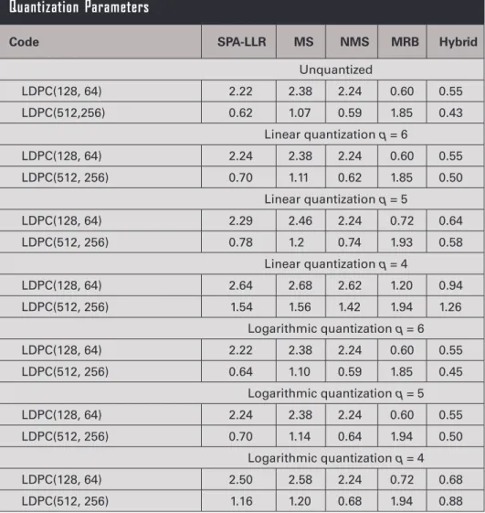
Table 5 reports the Es/N0
val-ues, obtained through simulation, required by the considered decod-ing algorithms to achieve the target CER = 10−5 with the two codes. Both
the unquantized (i.e., ideal) and the quantized cases, for different val-ues of the number q of quantization levels, have been analyzed. We have used two quantization rules: linear and logarithmic (i.e., with denser quantization levels around the zero signal amplitude). Looking at the un-quantized case, for the short code the best performance is achieved by the hybrid algorithm, with a gain in the order of 1.67 dB over the SPA-LLR. The hybrid algorithm is also the best for the long code, but the gain is just 0.16 dB over the NMS algorithm, the latter offering the best performance among the iterative algorithms. This is because the value of l in the “or-der-l reprocessing” stage of the MRB algorithm [9] is upper bounded due to complexity issues. In these con-ditions, for the short code the MRB
Table 5.
Required E
s/N
0[dB] at CER = 10
–5for Various Decoding Algorithms and
Quantization Parameters
Code SPA-LLR MS NMS MRB Hybrid
Unquantized LDPC(128, 64) 2.22 2.38 2.24 0.60 0.55 LDPC(512,256) 0.62 1.07 0.59 1.85 0.43 Linear quantization q = 6 LDPC(128, 64) 2.24 2.38 2.24 0.60 0.55 LDPC(512, 256) 0.70 1.11 0.62 1.85 0.50 Linear quantization q = 5 LDPC(128, 64) 2.29 2.46 2.24 0.72 0.64 LDPC(512, 256) 0.78 1.2 0.74 1.93 0.58 Linear quantization q = 4 LDPC(128, 64) 2.64 2.68 2.62 1.20 0.94 LDPC(512, 256) 1.54 1.56 1.42 1.94 1.26 Logarithmic quantization q = 6 LDPC(128, 64) 2.22 2.38 2.24 0.60 0.55 LDPC(512, 256) 0.64 1.10 0.59 1.85 0.45 Logarithmic quantization q = 5 LDPC(128, 64) 2.24 2.38 2.24 0.60 0.55 LDPC(512, 256) 0.70 1.14 0.64 1.94 0.50 Logarithmic quantization q = 4 LDPC(128, 64) 2.50 2.58 2.24 0.72 0.68 LDPC(512, 256) 1.16 1.20 0.68 1.94 0.88
algorithm used alone ensures practically the same performance as the hybrid algorithm, while for the long code it is characterized by the worst performance, more than 1.4 dB away from the hybrid algorithm. This is because, for the MRB algorithm alone, the con-straints on the value of l are even stricter for the case of n = 512; the complexity is relaxed by resorting to the hybrid approach that however, as we will show afterward, remains rather distant from the theoretically achievable limits. So, also pondering its reduced complexity, NMS is preferable for the long code.
Figure 7a summarizes the CER performance of the best decod-ers for both codes, assuming no quantization. This means that the soft reliability values that the algorithms involve are represented with a very high precision (e.g., 32-bit floating point for each reli-ability value). The union bound (UB) [24] for the short code and the sphere packing bound (SPB) [25] for the long code are also plotted as benchmarks. The UB gives an estimate of the ML de-coder performance, which becomes more and more reliable for increasing SNR. The performance of the hybrid algorithm is at a distance of about 0.6 dB from the UB, thus confirming the good-ness of the hybrid approach when applied to the short code. The
SPB has a meaning similar to the Shannon capacity but, contrary to the latter, it is able to capture the finiteness of the code length. The distance of the curve for the NMS decoder (or even the hybrid decoder) from the SPB is rather large, on the order of 2 dB, thus confirming that, for the long code, margins exist for performance improvements.
From Table 5 we also see that using q ≥ 5 with the linear law is sufficient to have almost negligible losses with respect to the ideal case; on the other hand, q = 4 is enough with the logarithmic law that, however, is characterized by slightly higher complexity.
When applied to an LDPC iterative decoder, quantization involves both channel messages and decoder messages. In view of ensuring compliance with the current architecture, we should consider that, in a typical implementation, the soft quantization logic inside the transponder may be limited to 3 bits. Hence, the impact of q = 3 must be investigated. With such a small num-ber of quantization bits, it becomes of paramount importance to choose suitable clipping thresholds to limit the effect of noise. Moreover, a linear quantization law is adopted. Though the limit on the number of quantization bits should be set only on the channel messages (while the decoder messages can be quan-tized by using q = 6 without problems), in Figure 7b we have reported the CER curves resulting from different combinations of the quantization granularity, under NMS decoding. We see that, when using q = 3 for the channel messages and q = 6 for the decoder messages, the loss against the unquantized case is very limited, in the order of 0.15 dB for the short code and 0.2 dB for the long code.
According to [5], TFs are of variable length, so that each TF produces a variable number M of codewords. Besides the pay-load, the TF also includes a 40-bit header and (optionally) a 16-bit cyclic redundancy check (CRC) that, however, do not need to be discriminated from the data for the purposes of the CER analysis. We have 1 ≤ M ≤ 128 for the LDPC(128, 64) code and 1 ≤ M ≤ 32
Figure 7.
CER performance of the selected decoding algorithms: (a) unquan-tized case, (b) assuming q = 3 quantization bits for the channel and/or decoder messages.
Figure 8.
UCER performance of the LDPC(128, 64) code by using the SPA-LLR decoding algorithm and the MRB algorithm followed by the CRC.
Baldi et al.
for the LDPC(512, 256) code. Neglecting the impact of possible inaccurate frame synchronization, we can compute the frame error rate (FER) as FER = 1 – (1 – CER)M that, for sufficiently small CER, can be approximated as FER ≈ M · CER. The target value is FER = 10−3. It is possible to verify that the values of E
s/N0 required
to satisfy the requirement on the CER value, reported in Table 5, permit also to satisfy the requirement on the FER value for any number of codewords.
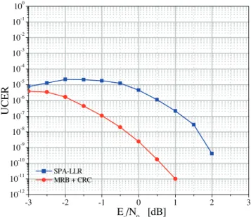
Finally, as mentioned, the UCER performance of the new codes is at least as important as the CER performance. Therefore, it deserves to be discussed as well. From the UCER viewpoint, there is a fundamental difference between the adoption of iterative decoding algorithms, like SPA-LLR, MS, and NMS, and the adop-tion of the MRB algorithm.
Iterative algorithms implement incomplete decoders, which means they are able, in most cases, to detect a decoding failure. This is also the feature which permits us to apply the hybrid ap-proach. The residual fraction of errors, that is the case when failures are not detected, is responsible for the UCER, which is normally much smaller than the CER. The UCER curve of the LDPC(128, 64) code, decoded by using the SPA-LLR algorithm, is shown in Figure 8. The curve has been obtained under the assumption of no quantization. We see that at Es/N0 ≈ 2 dB, that is, according to Table
5, the value required to achieve CER = 10−5, is able to guarantee
also UCER ≤ 10−9.
The situation is different for the MRB algorithm (and, conse-quently, for the hybrid algorithm). The latter, in fact, implements a complete decoder, which means that the decoder has no error detection capability and UCER = CER. So, looking, for example, at Figure 7a, we should conclude that values of Es/N0 much larger
than that necessary for satisfying the requirement on the CER must be applied, this way frustrating the advantage of using the MRB algorithm. In this case, however, it is possible to exploit the CRC. The latter is deputed to detect errors at the output of the MRB decoder and, taking into account the properties of the error pat-terns, that are LDPC codewords in turn, it is possible to verify [26] that its performance is quite adequate to comply with the UCER requirement. The resulting curve for the LDPC(128, 64)
code is shown in Figure 8. The analysis could be repeated for the LDPC(512, 256) code, for which satisfying the requirement on the UCER is even simpler.
HW IMPLEMENTATION CONSIDERATIONS
The study activity includes an HW proof-of-concept of the new advanced uplink coding techniques. For this purpose, a breadboard able to demodulate and decode uplink signals has been developed. For the breadboard design, the current telemetry, tracking, and command (TT&C) architecture and the optimizations required to incorporate the novel techniques must be considered; at the same time, the demonstrator goals, algorithm validation, and evaluation drive the overall design.
The architecture is based on a System-on-Chip (SoC) ap- proach fully contained in an FPGA device, where a micropro-cessor is embedded, performing digital signal processing (DSP) functions for TT&C transponder processing. The microproces-sor interfaces all DSP blocks and all other peripherals on-chip through a bus, which allows it to control and configure every TC receiver processing unit. This approach offers the advantage of a configurable, modular, and synchronous architecture, al-lowing portability, modification, or addition of DSP cores. The breadboard architecture is presented in Figure 9, where the HW/ Software (SW) partition of the different TC processing units is also shown.
This flexible platform permits us to deal with both NE and DS links requirements. The modular architecture allows incorporating critical components for test-bench fulfillment, such as monitoring units or communication interfaces for configuration and control in the test campaign. Furthermore, for the low data-rate DS sce-nario, most of the novel functions can be fully implemented in the SW domain. In particular, SW processing is well-suited for closing complex carrier and subcarrier tracking loops with HW domain. In addition, SW flexibility can support the higher complexity of MRB decoding, where a mixed HW/SW implementation is fore-seen. Indeed, the SW part of the MRB algorithm can be in charge of matrix operation and vector reordering, while the HW
paral-Figure 9.
lelization can be exploited to carry out the large number of binary operations needed.
CONCLUSIONS AND OUTLOOK
In this article, we presented a survey of next generation decoders and receiver chain for space TC links. Through a comprehensive analysis and assessment of receiver functionalities for the TC up-link, we were able to identify the receiver bottlenecks and to propose alternative receiver enhancements. The main outcomes and design guidelines resulting from the study are summarized in Table 6.
The study provides an explicit demonstration of the feasibility of the new receivers, paving the way for a more effective manage-ment of TC links in future missions.
ACKNOWLEDGMENT
The present contribution describes the achievements obtained within the ESA's Basic Technology Research Programme entitled Next Generation Uplink Coding Techniques (NEXCODE), Con- tract No. 4000111690/14/NL/FE, led by Deimos Engenharia, Por-tugal, as prime contractor.
REFERENCES
[1] Massey, J. Deep-space communications and coding: A marriage made in heaven. In Lecture Notes in Control and Information Science, (Vol. 182 of Advanced Methods for Satellite and Deep Space Commu-nications), J. Hagenauer, Ed. Heidelberg, Germany and New York: Springer, 1992, 1–17.
[2] Calzolari, G. P., Chiani, M., Chiaraluce, F., Garello, R., Paolini, E. Channel coding for future space missions: New requirements and trends. Proceedings of the IEEE, Vol. 95, 11 (Nov. 2007), 2157–2170. [3] de Cola, T., Paolini, E., Liva, G., Calzolari, G. Reliability options for
data communications in the future deep-space missions. Proceedings
of the IEEE, Vol. 99, 11 (Nov. 2011), 2056–2074.
[4] CCSDS, Next Generation Uplink. Green Book, CCSDS 230.2-G-1, Jul. 2014.
[5] CCSDS, TC Synchronization and Channel Coding. Blue Book, CC-SDS 231.0-B-2, Sep. 2010.
[6] ECSS, Space Data Links—Telecommand Protocols, Synchronization and Channel Coding. ECSS-E-ST-50-04C, Jul. 2008.
[7] NASA, Uplink Coding for New TC Standard. Draft Orange Book, Consultative Committee for Space Data Systems (CCSDS), Newport Beach, CA, Apr. 2008.
[8] Costantini, L., Matuz, B., Liva, G., Paolini, E., Chiani, M. Non-binary protograph low-density parity-check codes for space communications.
International Journal of Satellite Communications and Networking,
Vol. 30, 2 (Mar./Apr. 2012), 43–51.
[9] Baldi, M., Chiaraluce, F., Garello, R., Maturo, N., Aguilar Sanchez, I., Cioni, S. Analysis and performance evaluation of new coding op-
tions for space telecommand links—Part I: AWGN channels. Interna-tional Journal of Satellite Communications and Networking, Vol. 33,
6 (Nov./Dec. 2015), 509–525.
[10] Baldi, M., Bianchi, M., Chiaraluce, F., Garello, R., Aguilar Sanchez, I., Cioni, S. Advanced channel coding for space mission telecommand links. In Proceedings of the 2013 IEEE 78th Vehicular Technology
(VTC 2013-Fall), Las Vegas, NV, 2–5 Sep., 2013.
[11] Liva, G., Paolini, E., Matuz, B., Scalise, S., Chiani, M. Short turbo codes over high order fields. IEEE Transactions on Communications, Vol. 61, 6 (Jun. 2013), 2201–2211.
[12] Baldi, M., Chiaraluce, F., Garello, R., Maturo, N., Aguilar Sanchez, I., Cioni, S. Analysis and performance evaluation of new coding options for space telecommand links—Part II: Jamming channels.
Interna-tional Journal of Satellite Communications and Networking, Vol. 33,
6 (Nov./Dec. 2015), 527–542.
[13] Martinelli, P., Cianca, E., De Sanctis, M., Di Paolo, L., Pisano, A., Simone, L. Robustness of satellite telecommand links to jamming at-tacks. In Proceedings of the IEEE First AESS European Conference on
Satellite Telecommunications (ESTEL), Rome, Italy, 2–5 Oct., 2012.
[14] CCSDS, Short Block Length LDPC Codes for TC Synchronization and Channel Coding. Orange Book, CCSDS 231.1-O-1, Apr. 2015. [15] ECSS, Radio Frequency and Modulation, ECSS-E-ST-50-05C, Oct.
2011.
[16] Massey, J. L. Optimum frame synchronization. IEEE Transactions on
Communications, Vol. COM-20, 4 (Apr. 1972), 115–119.
Table 6.
Main Outcomes and Design Guidelines Resulting from the Study
Acquisition and Tracking Critical issues due to very low SNR values discussed. Most appropriate carrier, subcarrier and symbol tracking techniques addressed, depending on mission scenarios.
Frame synchronization Need to lengthen the start sequence up to 64 bits demonstrated. Most convenient low-complexity, but near optimal, methods for pattern recognition identified for both start and tail sequence recognition.
Decoder Error rate performance of the best decoding algorithms for the new codes properly addressed. Impact of quantization analyzed. Residual Undetected Error Rate evaluated.
Hardware implementation considerations Proper architecture described. Main bottlenecks in the current on-board architecture highlighted and suitable enhancements proposed for circumventing them, particularly in the most severe DS scenario.
Baldi et al.
[17] Chiani, M., Martini, M. G. On sequential frame synchronization in AWGN channels. IEEE Transactions on Communications, Vol. 54, 2 (Feb. 2006), 339–348.
[18] Pfletschinger, S., Navarro, M., Closas, P. Frame synchronization for next generation uplink coding in deep space communications. In
Pro-ceedings of the IEEE Globecom Conference 2015, San Diego, CA,
5–6 Dec., 2015.
[19] Hagenauer, J., Offer, E., Papke, L. Iterative decoding of binary block and convolutional codes. IEEE Transactions on Information Theory, Vol. 42, 2 (Mar. 1996), 429–445.
[20] Fossorier, M., Mihaljevic, M., Imai, H. Reduced complexity iterative decoding of low-density parity check codes based on belief propaga-tion. IEEE Transactions on Communications, Vol. 47, 5 (May 1999), 673–680.
[21] Chen, J., Fossorier, M. P. Near optimum universal belief propagation based decoding of low-density parity check codes. IEEE Transactions
on Communications, Vol. 50, 3 (Mar. 2002), 406–414.
[22] Fossorier, M., Lin, S. Soft-decision decoding of linear block codes based on ordered statistics. IEEE Transactions on Information Theory, Vol. 41, 5 (Sep. 1995), 1379–1396.
[23] Baldi, M., Chiaraluce, F., Maturo, N., Liva, G., Paolini, E. A hybrid decoding scheme for short non-binary LDPC codes. IEEE
Communi-cation Letters, Vol. 18, 12 (Dec. 2014), 2093–2096.
[24] Garello, R., Pierleoni, P., Benedetto, S. Computing the free distance of turbo codes and serially concatenated codes with interleavers: Al-gorithms and applications. IEEE Journal on Selected Areas in
Com-munications, Vol. 19, 5 (May 2001), 800–812.
[25] Valembois, A., Fossorier, M. P. C. Sphere-packing bounds revisited for moderate block lengths. IEEE Transactions on Information
Theo-ry, Vol. 50, 12 (Dec. 2004), 2998–3014.
[26] Baldi, M., Maturo, N., Ricciutelli, G., Chiaraluce, F. On the error de-tection capability of combined LDPC and CRC codes for space tele-command transmissions. In Proceedings of the 21st IEEE Symposium
on Computers and Communications (ISCC 2016), Messina, Italy,
27–30 Jun., 2016, 1105–1112.
AUTHOR AFFILIATIONS
Marco Baldi, Dipartimento di Ingegneria dell’Informazione, Uni-versità Politecnica delle Marche, Via Brecce Bianche 12, 60131 Ancona, Italy; Massimo Bertinelli, ESA-ESTEC, Keplerlaan 1, Noordwijk, The Netherlands; Franco Chiaraluce, Dipartimento di Ingegneria dell’Informazione, Università Politecnica delle Marche, Via Brecce Bianche 12, 60131 Ancona, Italy; Pau Closas, formerly with Centre Tecnològic de Telecomunicacions de Catalunya, Parc Mediterrani de la Tecnologia, Av. Carl Friedrich Gauss 7, 08860 Castelldefels, Barcelona, Spain; now with Northeastern University, 360 Huntington Avenue, Boston, MA 02115, USA; Pawan Dhakal, Dipartimento di Elettronica e Telecomunicazioni, Politecnico di To-rino, Corso Duca degli Abruzzi, 24, 10129 Torino, Italy; Roberto Garello, Dipartimento di Elettronica e Telecomunicazioni, Politec-nico di Torino, Corso Duca degli Abruzzi, 24, 10129 Torino, Italy; Nicola Maturo, Dipartimento di Ingegneria dell’Informazione, Università Politecnica delle Marche, Via Brecce Bianche 12, 60131 Ancona, Italy; Monica Navarro, Centre Tecnològic de Telecomu-nicacions de Catalunya, Parc Mediterrani de la Tecnologia, Av. Carl Friedrich Gauss 7, 08860 Castelldefels, Barcelona, Spain; José María Palomo, Deimos Space S.L.U., Ronda Poniente, 19, Edificio Fiteni VI, P.2, 2º, 28760 Tres Cantos (Madrid), Spain; Enrico Paolini, Department of Electrical, Electronic, and Informa- tion Engineering “G. Marconi”, University of Bologna, Via Vene-zia 52, 47521 Cesena (FC), Italy; Stephan Pfletschinger, formerly with Centre Tecnològic de Telecomunicacions de Catalunya, Parc Mediterrani de la Tecnologia, Av. Carl Friedrich Gauss 7, 08860 Castelldefels, Barcelona, Spain; now with Hochschule Offenburg, Badstraße 24, Offenburg, Germany; Pedro Freire Silva, Deimos En-genharia S.A., Av. D. Joao II, No.41, 10th Floo, 1998-023 Lisbon, Portugal; Lorenzo Simone, Thales Alenia Space, via Saccomuro 24, 00131 Rome, Italy; Jordi Vilà-Valls, Centre Tecnològic de Teleco-municacions de Catalunya, Parc Mediterrani de la Tecnologia, Av. Carl Friedrich Gauss 7, 08860 Castelldefels, Barcelona, Spain.