OATAO is an open access repository that collects the work of Toulouse
researchers and makes it freely available over the web where possible
Any correspondence concerning this service should be sent
to the repository administrator:
tech-oatao@listes-diff.inp-toulouse.fr
This is an author’s version published in:
http://oatao.univ-toulouse.fr/23048
To cite this version:
Tułodziecki, Michal and Tarascon, Jean-Marie and Taberna, Pierre-Louis and
Guéry, Claude Importance of the double layer structure in the electrochemical
deposition of Co from soluble Co2+ - based precursors in Ionic Liquid media.
(2014) Electrochimica Acta, 134. 55-66. ISSN 0013-4686
Importance of the double layer structure in the electrochemical
deposition of Co from soluble Co
2+ -based precursors in Ionie
Liquid media
M. Tulodziecki
a,J.-M. Tarascon
a,P.L. Taberna
b, C.Guéry
a,*a Laboratoire de Réactivité et Chimie des Solides and ALISTORE European Research Institute, UMR CNRS 7314, UFR des Sciences, 33 rue Saint Leu, 80039 Amiens cedex, France
b CIRIMAT/LCMIE and ALISTORE European Research Institute, UMR CNRS 5085, 31062 Toulouse cedex 9 -France
ARTICLE INFO ABSTRACT
Keywords: Double Layer Ionie liquids Electrodeposition Cobalt EQCM Impedance Spectroscopy
Electrodeposition in Ionie Liquid (IL) media is being widely used to obtain different metals, alloys and more recently binary compounds. However, the understanding of this process is still slim due to poor knowledge in the chemistry of!Ls and also the complex structure of the double layer at the electrode sur face. It is then difficult to predict deposition conditions when trying to synthesize a desired deposit. In this work, we provide insight into the processes taking place at the electrode by detailed studies of Co2• redue tian in ionic liquid media at elevated temperature, which have revealed an unusual Cyclic Voltammetry profile. A drastic drop in the reaction rate was observed, together with a well-shaped reduction peak dur ing the oxidation sweep. Using Electrochemical Quartz Crystal Microbalance, Impedance Spectroscopy measurements and varying bath parameters, we ascribed those phenomena to the reconstruction of the double layer structure upon imposed polarization. Similar behaviors were observed for other systems (Mn2•, NF•, zn2•). Finally, this work provides new insight into the electrochemical processes in !Ls. We anticipate that it will also result in significant improvement in preparing metal and other deposits in the ionic liquid media.
1. Introduction
Ionie liquids (!Ls) have received great attention in recent years as a media for electrodeposition thanks to their attractive chemi cal/physical properties. They are non-flammable, display very high thermal stability together with negligible vapor pressure, and are good sol vents for numerous salts and polymers. Their wide window of electrochemical stability and relatively high conductivity have allowed the electrodeposition of less noble metals, semiconductors and alloys that could not be accomplished in aqueous solution due to its limited potential window and thermal stability[l-7]. More recently binary compounds such as sulfides[8,9] and metal oxides[l0-12] have been electrodeposited from IL baths, opening new possibilities for this media.
An issue of primary importance regarding electrodeposition processes is the structure of the double layer and its behavior under applied potential which is different in !Ls, aqueous solution and
* Corresponding author.
E-mail address: claude.guery@u-picardie.fr (C. Guéry).
http://dx.doi.org/10.1016/j.electacta.2014.03.042
other molecular sol vents. It has been proven both theoretically and experimentally that the cations and anions of !Ls are highly struc tured, forming layers within the double layer [ 1, 13-16]. Depending on surface polarization, the arrangement and conformation of the anions and cations may change as proven by Atomic Force Microscopy[l 7] and Sum Frequency Generation Spectroscopy[18]. Cobalt and its alloys are very important functional materi als due to their magnetic properties, and resistance to corrosion, temperature and wear. Electrodeposition of Co is relatively dif ficult from aqueous solutions due to hydrogen evolution[19,20], necessitating to shift to more stable solvents such as ionic liq uids. Katayama's[21,22] and Guo's[23] studies have shown that Co2+ undergoes 2e- reduction with high overpotential. Slow kinet
ics of the reduction process was ascribed to the existence of a huge octahedral cobalt complex [Co(TFSihJ-. Katayama et al. have further shown that the reduction overpotential decreases with temperature, and they attribute this effect to the dissociation of the [Co(TFS!hJ- complex, based on the change of bath color from pink ( octahedral complexation) to blue (tetrahedral complexation) at high temperature[21 ]. The tetrahedral cobalt complex was also obtained by either changing a cobalt sait (CoCl2 in BMPTFSI)[24] or
by adding strong organic complexing agents as TU[22,25]. Despite ail these researches, issues dealing with double layer structur ing and cation complexation, which are of crucial importance for understanding and planning electrochemical processes in IL media, are still not well known, hence our motivation to address them.
In this study, we perform a detailed investigation of the Co2+ /Co
electrochemical reduction process in ionic liquid media by explor ing the influence of temperature, substrate, nature of the ionic liquid (with focus on EMimTFSI), and complexation ofCo2+. Special
attention is devoted to the fundamental aspects of the processes taking place at the electrode surface via the complementary use of Electrochemical Quartz Crystal Microbalance (EQCM), Cyclic Voltammetry (CV) and Impedance Spectroscopy (IS) measure ments. Sorne interesting phenomena, never reported previously for the Co2+ /Co system, have been unravelled. Finally we attempt to
explain them based on our results and the large amount ofliterature data on ionic liquids.
2. Experimental
The electrochemical bath was composed ofCo(TFSih (Solvionic) solution in IL either EMimTFSI, OMimTFSI, BMPTFSI, BMimTfO or tBMNTFSI ordered from Solvionic, 99.9% pure (H2O < 0.005%), Table 1. Prior to being used, the !Ls were purified under vacuum at 75 °C for 2 days; the final water content was ~6 ppm as checked by Karl Fischer measurement. The complexing agent Thiourea (from Aldrich) was used as received. The Co(TFSih sait was chosen as cobalt cation precursor in order to avoid the addition of highly corrosive chlorides (CoCl2). If not otherwise specified, the initial concentration of cobalt cations was 0.12 M. Ali the substances were kept in an argon-filled glove box (02 and H2O<0.1 ppm). In ail
TFSJ- based ILs (containing only Co2+ cations) the color of the bath
was purple indicating octahedral coordination of cobalt cations [Co(TFSih
1-.
We have just noted a minor change of the bath color (0.12 M Co(TFSI)2 in EMimTFSI) from purple (RT) to dark purple upon heating (up to 200 °C), suggesting only a slight tempera ture influence on the cobalt coordination. This contrasts with the results presented by Katayama et al. where the solution of Co(TFSih in BMPTFSI changed to blue at high temperature[21 ]. However Raman/IR results have recently revealed the absence of change in coordination number as a function of temperature, although the conformational equilibrium in the coordination sphere (between two most stable states cis and trans) has been found to be strongly dependent[26].A three-electrode set-up was used for electrochemical mea surements (chronoamperometry, cyclic voltammetry, impedance spectroscopy). Five different substrates were used as working elec trodes (WE): platinum dise (Ptd) S = 1.78 cm2, platinum planar
electrode (Ptp) S=0.020 cm2, glassy carbon planar electrode (GC)
S=0.071 cm-2, platinum and stainless steel wires (Ptw and SSw
respectively). The surface area of the last one was estimated accord ing to the Iength of the dipped part (surface ranging from 0,01 7 to 0,033 cm2). The counter electrodes (CE) were platinum grids with
high surface area (S Rej 2 cm2 and 10 cm2 depending on the chosen
WE). An Ag wire covered with Ag2O was used as the pseudo ref
erence electrode (RE). The stability of RE at high temperature has been checked by means of OCP stability and reproducibility. It was found stable enough for the purpose of our experiments. Ali the values of potential will be given versus the pseudo Ag/Ag2O refer
ence electrode if not otherwise specified. Prior to being used, the platinum WEs were annealed in 0.5 M H2SO4 in order to obtain a
stress-free and clean surface (the CV profile patterns were compa rable with now standard ones representative of an impurity free Pt surface)[27]. Next, the electrodes were rinsed with distilled water, ethanol, acetone and deionized water. The CE electrode was cleaned
in 0.5 M nitric acid in an ultrasonic bath for 1 h, and then inten sively rinsed with distilled water, ethanol, acetone and deionized water. Ali the components of the cell were dried in an oven at T = 50 °C for 2 hours before the experiment. Preparation of the solu tion and assembly of the cell were done in a glove box. The cell was immersed in an oil bath white the temperature was controlled with ± 2 °C difference between heating and deposition bath.
The electrochemical measurements were carried out with an Autolab PGSTAT 30 potentiostat (Eco Chemie BV). The impedance measurements were conducted with a Biologie VSP potentiostat; collection of impedance data started after the system reached steady state conditions at fixed potential. The chosen frequency ranged from 1 MHz to 50mHz white the amplitude of sinusoidal potential was set to 10 mV. Ali the CV measurements were per formed starting from the OCP with a reduction scan followed by the oxidation one if not otherwise specified.
The obtained deposits on Ptd were soaked in chloroform to rem ove adsorbed IL from the surface. Their morphologywas further analyzed using a Philips XL 30 field emission gun FEG microscope. EQCM measurements were carried out using a commercial SEIKO microbalance with AT-eut 9 MHz quartz covered with plat inum on both sides. The electro-active geometric surface area was equal to S = 0.196 cm2• Simultaneous measurements of the quartz
frequency and motional resistance were done in order to follow both the change in mass and the variation in Co2+ concentration
in the vicinity of the electrode (by following the change of viscos ity and density product of the solution)[12,28,29]. The EQCM was calibrated with CV measurement in 0.05 M solution of AgTFSI in EMimTFSI, at 100 °C, with 2 mV•s-1 scanning rate. The proportion
ality constant ( �m = C. �f) was determined between the change of quartz frequency (�f) and change of deposited mass (�m)[30]. A constant value C = 1.065-10-9 g-Hz-1 close to the theoretical one
Ct = 1.068-10-9 g-Hz-1 was found, suggesting that issues regarding
viscosity of the bath or roughness of the substrate can be neglected. So, to analyze the EQCM data, the function M/z (molar mass over number of exchanged electrons) was simply calculated according to Sauerbrey equation (1) and Faraday's Iaws of electrolysis (2), assuming that the reaction efficiency is near 100% (3). The M/z value was calculated from the �f and �Q difference between each adjacent point. Llm
=
-CL\f Llm= (
L\ FQ) ( �) M =-(FC) L\f z L\Q (1) (2) (3) The expected value ofM/z for the growth of Co, which relies on a 2 e- process, is 29.5 g•mol-1. The CV with scanning rate 2mV.s-1and probe time 1s, was performed in 0.12 M Co(TFSih solution in EMimTFSI at 100 °c under Ar atmosphere.
Ali the experiments were done several times to check the repeatability. We would also like to mention that Co2+ /Co+
symbols are mostly written as cobalt species in the solu tion instead of complexated forms, which they are in reality ([Co(TFSihJ-/[Co(TFSI)x]Y-), although we corne back to the latter when it is needed for the sake of clarity.
3. Results
3.1. Cyclic Voltammetry in EMimTFSI
We initially checked the electrochemical response of 0.12 M Co2+ solution in EMimTFSI IL, at 100 °c, on 3 different sub
strates: Ptp, GC and SSw (Fig. 1a, b, c respectively). Whatever the nature of the substrate, CVs revealed identical features during the
Table 1
Abbreviations for the IL components and their structures.
IL component full name Abbreviation
1-ethyI-3methylimidazolium cation EMim• 1-butyl-3methylimidazolium cation BMim• 1-octyl-3methylimidazolium cation OMim•
tri-butyl-methyiammonium cation tBMW
1-butyl-1-Methyipyrrolidinium cation BMP•
bis(trifluoromethylsulfonyl)imide anion
TFSI-trifluoromethanesuifonate anion
Tfo-dicyanamide anion
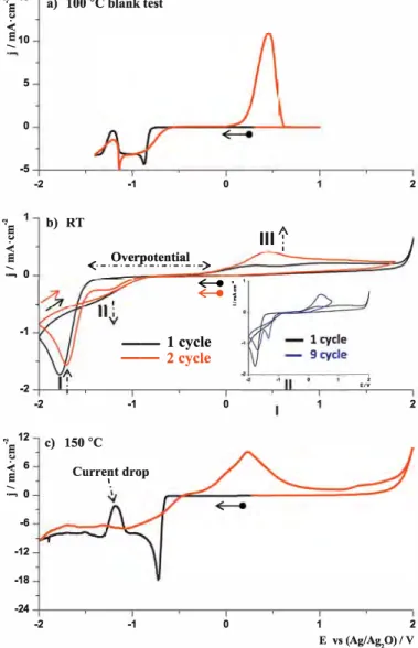
reduction and oxidation sweeps (Fig. 1 I, II, III, IV, V, insets). Follow ing the reduction sweep on the Ptp electrode (Fig. la, black curve), the first reduction peak with an onset at -0.70V and centered at -0.88 V (1) is ascribed to Co2+ reduction. The reduction starts at a
high overpotential of ~0.8 V as compared to the coupled oxida tion process (onset ~0V). Subsequently, between -0.9V and -1.1 V a diffusion limited process appears as the current density tends to stabilize. At lower potentials, the reduction current density sud denly drops and reaches a minimum at -1.20V (II). Afterwards, the reduction current density increases again and reaches the maxi mum at -1.38 V (III), which we again assigned to the reduction of Co2+. The value of the limiting current density below -1.38 V is simi
lar to the one of diffusion limited reaction taking place between-0.9 and-1.1 V. On the reverse sweep (Fig. 1 a, red curve ), the current density progressively decreases and reaches a minimum at slightly higher potentials (-1.18 V) in comparison to the reduction sweep (-1.20V). Above -1.18V, a very sharp reduction peak centered at -1.09 V is observed (IV), followed by a diffusion limited and then a diffusion/activation limited reduction process. The oxidation sig nal at more positive potentials was ascribed to Co stripping. The reversibility (the charge ratio between oxidation and reduction process) of the electrochemical reaction is above 75%; however, it varies according to the chosen reverse potential reaching almost 100% at higher potentials (Supplementary Materials (SM), Fig. 1 *). Such aforementioned features, namely the drop in current density around -1.2 V and the oxidation peak on the reverse sweep, were
Structure --N 0/� --N0;N� --N0;N�
'---Gf
î\/\
"�
0
·+�-i-�+·
F O O Falso observed for the other substrates with slight shifts in onset and peak potentials (Fig. 1 b, c).
3.2. EQCM measurement
Both the huge drop in current during the reduction sweep and the well-defined reduction peak during the oxidation sweep are rare phenomena in electrochemistry. To gain further insight into the origins of these unusual features, we have conducted an EQCM measurement which is an elegant technique to indirectly deter mine the mass of the deposit as well as the concentration of Co2+
near the electrode via quartz frequency and motional resistance changes, respectively. Cyclic voltammetry at a rate of 2 mv.s-1, at 100 °c, in 0.12 M Co(TFSI)z was performed. The reverse poten tial was chosen at the minimum of the current drop during the reduction sweep (-1.20 V).
Figs 2a, b, c, d show current, quartz frequency, quartz resistance and M/z variations versus potential, respectively. The current pro file is almost identical to the one obtained on the Ptp electrode in the same conditions (Fig. la). A shift in potential is visible most likely due to minor differences in the Pt surface, which in case of quartz is electrochemically mirror polished as opposed to mechan ically. Whatever the origin of the shift, a drop in current density with the minimum at -1.20V and a very sharp reduction peak dur ing the oxidation sweep are still observed. The reduction of Co2+
,., 15
·a
:::, 10 5 a) PtpV
■ - ■ - ■ - ■ - ■ - ■ - ■ 0--
-+
-
---===-
-
-....l..---1 -5l-. -. - . - . -. -. - _1 ,., 15·a
:::, 10 5 -1.5 , 0 5 � ::::.-1 -3 -1.0 -0.5 0.0 0.5 1.0 b) GCV
-5 -+---�-�-�----�---�--�� -1.5 -1.0 -0.5 5..
IV
.. +---�
�-·
�.2 -1.0 -0.8....
E vs (Ag/Ag,O)/ V -1.5 -1.0 -0.5o.o
0.0V
0.5 1.0 c) SSw 0.5 1.0 E vs(Ag/Ag,0)/VFig. 1. CV's curves of0.12 M Co(TFSih solution in EMimTFSI at 100 °C, on: a) Ptp, b) GC, c) SSw electrode. The black curve presents the reduction sweep while the red oxidation sweep. CE-Pt, RE-Ag/Ag20, scanning rate 5 mv-s-1. Inset: magnification
of negative potential part.
at-0.96 V. A time derivative of the current (SM, Fig. 2a*) reveals two weak anomalies at-0.88 and -0.92 V. Further, comparing CV (Fig. 2a) and variation in quartz frequency (Fig. 2b) between 0.87 and -0.90 V ( within the blue dashed lines potential window, Fig. 2 ), a high reduction current density is observed while only small changes in frequency occurred (clearly visible on the time derivative of the frequency which is proportional to the current according to Sauer bay and Faradays equations - SM, Fig. 2b*). Additionally, a small decrease in motional resistance (Fig. 2c) is observed, attributed to the change of viscosity/density properties of the solution in the vicinity of the electrode. ln our opinion, this part of the reduction process involves only soluble species with 1e- reduction process ofCo2+ (equation 4), and the aforementioned variation in motional
0 -1 -2 -3 -4 a) Current profile i i -0.8 -0.7 -0.6 -0.5 -1.3 -1.2 -1.1 -1.0 -IJ,9 0 ·0 b) Frequent change
-+-+
---�----2.0x10⁴ -4.0x10⁴ -6.0x10⁴-+-
- ---
--+
---
+-+--r-
---1.3 -1.2 -1,1 -1.0 � 960 c) Resistanc1 change � 940 920 -1.3 -1.2 -1,1 -1.0 : d) �zv�r 30 î---,;,,'�-...;,,--.;;..= 25 20 15 -0.8 -0.7 -0.6 -0.5 � -0.7 -0.6)
-0.5 Reduction sweep Oxidation sweep 10-+-____ __,_ _____ _,___-'----,-_______ _ _ -1.3 -1.2 -1.1 -1.0 -0.9 -0.8 -0.7 -0.6 -0.5 E vs (Ag/Ag20) / VFig. 2. EQCM measurement a) current versus potential, b) quartz frequency change versus potential, c) quartz motional resistance versus potential, d) calculated M/z value for the reduction sweep-green curve and oxidation sweep-gray curve, the black dashed line indicates the theoretical M/z value of Co formation. Blue dashed lines divide the CV curve into regions where different phenomena occur. 0.12 M Co(TFSI)2, T= 100 'C, WE-Pt mirror polished on quartz, CE-Pt, RE- Ag/Ag20, scan
rate 2mV.s-1.
resistance is due to the change in the coordination sphere of Co2+
as it is reduced. co2+ + e- - co+ soluble � soluble
Coioluble + e- r= COsoild
co;:,uble + 2e- r= COsoild
(4) (5)
(6)
Below -0.9 V, there is a significant decrease in frequency that is accompanied by the appearance of a dark deposit on the quartz, indicating the consumption of Co2+ /Co+ cations according
to equations (5) and (6). This leads to a decrease of solution vis cosity/density, in agreement with the quartz motional resistance
change (Fig. 2c) that suddenly starts to decrease and then stabilize at R= 915 Q in the region of the diffusion limiting step (-1.0/-1.1 V). Calculated M/z values (Fig. 2d) start to progressively increase reach ing a maximum of 42 g-mol-1 at E=-0.97V. This maximum most
likely originates from the simultaneous reduction of Co2+ and co+
species which should theoretically give M/z values of 29.5 g-mo1-1
and 59 g-mo1-1, respectively. Afterwards, M/z stabilizes at a value of 29-30 g-mo1-1 indicating a direct 2 electron Co2+ reduction process
at lower potentials (equation 6). Once the current density starts to drop (below -1.1 V, blue dashed line Fig. 2), the frequency tends to stabilize due to a slowdown in the deposition rate; more impor tantly, the motional resistance increases dramatically (increase in viscosity and density product) reaching 935 Q. This is in relation with the diffusion of the Co2+ in the vicinity of the electrode, equal
izing its concentration with the bulk one.
When the potential is reversed, a huge and very sharp reduction peak is observed. It is linked to both a sudden increase in the depo sition rate and a decrease in motional resistance (drop in viscosity and density product). This means that Co2+ reduction resumes
rapidly with therefore the onset of a diffusion limiting process (as further suggested by the constancy of the motional resistance) at the plateau of the motional resistance value (R=905 Q). Overall, from the current profile, quartz frequency and quartz motional resistance variation, it seems that the reduction of Co2+ around
-1.2 V is inhibited by a reversible potential triggered phenomenon. At this stage, it should be recalled that the quartz motional resistance does not solely depend on the bath viscosity and density product; other parameters such as viscoelasticity, rough ness or adhesion of the deposit also contribute to the motional resistance[29,31 ]. However, in our case, the shape of the motional resistance curve follows the change in current density which is pro portional to the change of Co2+ concentration. The change in Co2+
content affects the structure of IL in the vicinity of the electrode (diffuse layer of Co2+) that acts as a viscoelastic film on the quartz
electrode. Any variation in IL structure leads to changes in the viscosity/density parameter consequently affecting the motional resistance. Additionally, note that during the diffusion limited reduction process (-1.1 V to -0.8 V on oxidation sweep and -1.0 to -1.1 V on reduction sweep ), the motional resistance remains almost constant (R R; 905 Q). Moreover its value is close to the quartz resis
tance in pure IL solution at 100° C (R = 895 Q), white there is still
a progressive evolution of the deposit. This led us to conclude that the growth of the Co deposit has negligible impact on the resis tance which mostly depends on the properties of the diffuse layer (viscosity/density) that is related to Co2+ concentration.
3.3. Influence of the bath parameters
In order to further investigate the origin of the sudden drop in current density during reduction at -1.20 V (Fig. 1 ), the influence of temperature, IL formulation, and complexation of Co2+ cations on
the CV response were checked. Ali the experiments were conducted on the Ptw electrode if not otherwise specified. The CV curve col Iected at 100 °C in 0.12 M Co(TFSI)
2 in EMimTFSI (Fig. 3a) is a blank
test that will be treated as a reference through the rest of this paper.
3.3.1. Temperature
Fig. 3 represents CV curves of 0.12 M Co(TFSI)2 solutions at dif
ferent temperatures. At RT (Fig. 3b, black curve), a single peak (1) with huge overpotential ( ~ 1.5 V) is observed as opposed to two at 100°C. However during the next cycle (Fig. 3b, red curve) an
additional reduction peak (II) appears at slightly higher potentials ( onset at -1 V). The intensity of the reduction peak (II) progres sively increases with the number of cycles white the intensity of the reduction peak (I) decreases (Fig. 3b, inset); this suggests that in both reactions the same species, namely the Co2+ cations, are
.., 15 a)
e
"
�10 5 0 -5 -2"'e
b)"
<
e
:::, 0 -1 -2 -2"'e
12 c)<
6e
:::, 0 -6 -12 -18 -24 -2 100 °C blank test -1 0 RT -<· _. �_v_e_r_p�t_e_��'.1!.. ->�·
�
i
-- 1 cycle -- 2cycle -1 0 150 °C Current drop l -1 0 Ill1'
1 ' ' e,v 2 2 1 2 E vs (Ag/Ag,0) / VFig. 3. CV's curves of 0.12 M Co(TFSI)2 solution in EMimTFSI at different tempera tures a) blank test at 100°C b) 2 successive scans at RT, inset represents first and
ninth cycle, c) 150°C. WE-Ptw, CE-Pt, RE-Ag/Ag20, scanning rate 5 mv.s-1•
reduced. The reduction/oxidation process at RT is poorly reversible (33%) as on the reverse sweep, only a small oxidation peak (III) is visible during the first cycle (Fig. 3b, black curve). The reversibility improves upon cycling, due to the appearance of a new reduction peak (II) that is almost 100% reversible (SM, Fig. 3*). On the other hand, at high temperature (T = 150 °C, Fig. 3c ), the same phenomena
(onset of 2 reduction peaks together with a sudden drop in the current density) are observed alike at 100 "C. The minimum of the current density drop is slightly shifted to higher potentials (-1.18 V).
3.3.2. IL nature
One of the advantages of ILs is the possibility of playing with their formulation by substituting either their cation or anion, and hence changing greatly their physical and chemical properties and their interactions with cobalt cations and the substrate.
First, substitution of TFSJ- with Tfo- was investigated. Once the Co(TFSI)z is added to the TfO- based IL, its color changes to blue meaning that the coordination is no longer octahe dral ( [ Co(TFSlb J-) as in the case of EMimTFSI, but tetrahedral ([Co(Tf0)4J2-) as deduced from the collected UV-VIS spectra (SM, Fig. 4*). Fig. 4a shows the CV curve of 0.12 M Co(TFSI)z solution in EMimTfO IL at 100 °C. Although the shape of the peaks as well
2 '1Ê
<
a) EMimTfO at 100 °C Currentdrop 0 -1 -2 -1 '1EI...
4 b) OMimTFSI at 100 °C 3 successive scans<
:::, 2 0 -2 -4 Il -2 -1 '1 20 c) OMimTFSI at 150 °C...
<
:::, 10 Currentdrop 0 -10 0 2 111,t.. 1 1 cycle 2 cycle 3 cycle 0 2 -20-+---�
-2 -1 0 1 2 E vs(Ag/Ag,O)/V Fig.4. CVof0.12M Co(TFSI)2 solution: a) in EMimTfO at 100°C, b) in OMimTFSI at100°C 3 successive scans, c) in OMimTFSI at 150°C. WE-Ptw, CE-Pt, RE-Ag/Ag20,
scanning rate 5 mvs-1.
higher potentials), the two reduction peaks separated by a drop in current density are still visible, as well as the reduction peak on the oxidation sweep (SM, Fig. 5*).
The influence of imidazolium ring back bone was checked by substituting the EMim+ cation with OMim+. The successive CV
curves of 0.12 M Co(TFSl)z on the Ptw at 100°C in OMlmTFSI IL are
reported on Fig. 4b. On the first scan (black curve), a small reduc tion peak (!) starting at-0.89V and centered at -1.12 V followed by a huge reduction peak (11) with the onset at -1.30 V and centered at -1.62 V are observed; both features were assigned to the reduction
of Co2+. In the next scans, the intensity of both the reduction peak
(1) and the oxidation peak (III) increase. That is very similar to the CVs obtained in 0.12 M Co(TFSI)z in EMimTFSI at RT (Fig. 3b ); never theless, in the case of OMlmTFSI at 100 °c the intensity of the peak at -1.60 V (II) does not change upon cycling. At higher temperature (150 °(), the intensity of the first peak is greatly enhanced in com parison to the second one (Fig. 4c). Additionally, a very clear drop in current density is visible, reaching again the minimum at-1.20 V. Similarly, a reduction peak on the oxidation sweep is observed as well (more clear when the potential is reversed at -1.20 V, (SM,
Fig. 6*).
<;'e
8 a) BMPTFSI at 100 °C...
<
--....
4 0 -4 -2 -1 0 1<;'
4 b) tBMNTFSI at 100 °Ce
...
<
....
2 0 -2 --+---�---�--� -2 -1 0 1 E vs (Ag/Agp) / V Fig. 5. CV of0.12M Co(TFSI)2 solution in a) BMPTFSI at 100°C and b) tBMNTFSI at100 'C. WE-Ptw, CE-Pt, RE-Ag/Ag20, scanning rate 5 mvs-1•
Lastly, the IL cation was replaced by BMP+ and tBMW. ln both
cases, two reduction peaks are visible (Fig. Sa and b, respectively); however, the drop in current density is not so significant as for the imidazolium based Ils described above (the density current at the minimum of the drop is very high as compared to blank test, Fig. 3a ),
<;'
e
i
--15 --TU --TU+Co2+ 10 5 0 -5 -10---�-�-�-�--�---� -1.5 -1.0 -0.5 0.0 0.5 1.0 1.5 E vs (Ag/Agp) / V Fig. 6. CV curves ofEMlmTFSI solution containing 0.48 M 11J - black curve and 0.12 M Co(TFSI)i/0.48 M TU-red curve, at 100 "C on Ptp electrode. CE-Pt, RE-Ag/Ag20, scan ning rate 5 mv-s-1.a
-
�-E
':,> LLE
Q) (.) C:s
13 CU a. CU 0 >, CU C: Ol CU 200 a) Nyquist plot 160 0.2Hz 120 80/
"'
40 0 -40---♦- -1
.
00
V
_._
-
1.1
4V
...
-1.20V
-0---1.
2
6 V
--0--
-
1
.5
0
V
-80-+-��---�������-����� -120 -80 -40 0 40 80 120 160 10b) Complex Capacitance plot
2 ZReal
I
Q•cm 8 6-
♦
-
-1.00 V
_._
-
1
.
1
4
V
...
-1.20V
--0--
-
1.26 V
10 Real Capacitance I mF·cm·2Fig. 7. lmpedance spectroscopy of0.12M Co(TFSlh solution at 100°( at different
potentials a) Nyquist plots: 0.SV black filled squares, 1.00V red filled circles, -1.14 V green filled triangles, -1.20V blue filled tilted triangles, -1.26V brown open circles, -1.S0V purple open squares. b) Complex capacitance curves: -1.00V red filled circles, -1.14 V green filled triangles, -1.20V blue filled tilted triangles, -1.26V brown open circles. The inset represents zoom of the curves at very high frequencies. WE-Ptp, CE-Pt, RE-Ag/Ag,O.
even at high temperatures (SM, Fig. 7*). Additionally, the minimum of the current density drop is shifted to lower potentials, -1.34 V for BMP+ and -1.35 V for tBMW.
So overall, it turns out that the nature of the cation solely influ ences both the current drop during reduction and the reduction peak on the reverse sweep.
3.3.3. Complex charge
As a last part of our survey, the influence of the charge of the cobalt complex was investigated, which is negatively charged in either TFSJ- or Tfo- based IL. To assess such a parameter, a neutral complexing agent thiourea (known to produce positive [Co(TU)4]2+
complexes) was added to a 0.12M Co(TFSih solution in EMimTFSI
IL[22]. Upon addition of TU, the solution rapidly turns blue, mean ing that the complexation changed from octahedral [ Co(TFSih
J
to tetrahedral [Co(TU)4]2+. Fig. 6 displays the CV curves on the Ptpelectrode ofEMimTFSI solution containing 0.48 M TU (black curve) and 0.48 TU +0.12 M Co(TFSih (red curve). The same Ptp electrode with constant surface area was used in both cases to directly com pare the intensities. The stability window for the TU, which ranges from -1.0 to 0.8 V, can be widened upon the addition of metal cations. Lastly, the onset of TU oxidation shifts to 1 V (SM, Fig. 8*) while its reduction is highly hindered (Fig. 6). Indeed since the cur rent profile indicates steady state diffusion (Co2+ reduction) while
the solution with only TU reveals a continuous increase in current density. Reduction of the Co2+ starts at relatively high potential E =
-0.5 V and is followed by a single reduction wave without any current drop and reduction peak on the reverse scan, unlike previously described systems. Following the oxidation sweep, an additional oxidation wave is observed starting at 0.41 V (apart from Co strip ping process at 0.3 V), however, for the sake of conciseness, it will not be discussed further. We can thus conclude from the afore mentioned results that the charge of the complex is also one of the crucial parameters responsible for the unusual behavior observed during the reduction/oxidation sweeps.
3.4. Impedance spectroscopy: Nyquist and Cole-Cole plots
The dynamic aspect of the system was tested by potentio electrochemical impedance spectroscopy at different potentials (-0.80; -1.00; -1.16; -1.20; -1.26; -1.50 V). For each experiment, a newly prepared electrode was used. Ali the impedance spectra were collected after the steady state was reached at each applied potential. Fig. 7a reports the Nyquist impedance curves of 0.12 M Co(TFSih solution at 100 °c on the Ptp electrode. At -0.80 V (full black squares), a semicircle (42 Q.cm2 of diameter) is observed
and can be assigned to parallel association of the charge trans fer resistance and the double layer capacitance. As the potential decreases (-1,00 V), a sharp increase of the imaginary part, proba bly related to diffusion limitation, is noticed. At -1.14 V (green full triangles) and -1.20 V (blue full triangles) for lower frequencies, a second semicircle appears with the opposite sign of curvature, crossing the negative part of the real axis at fini te frequencies (neg ative impedance). This is in agreement with our CV curve, where in between -1.1 and -1.2 V a negative slope on the voltammo gram is observed (Fig. 1 a) leading to negative value of polarization resistance. The negative impedance further disappears at lower potentials (-1.26 and -1.50 V, brown empty circle and purple empty square, respectively) at the expense of a half semicircle (however a Warburg impedance cannot be excluded).
The above mentioned negative impedance is a part of wider con sideration on the stability nature of the system. If the intersection of the impedance spectra happened in the origin of the complex impedance plane, a Hopf-bifurcation (since the crossing happens at finite frequencies) would appear leading to an oscillatory current profile at fixed potential[32]. The shift of the intersection can be done by either applying a sufficient externat resistance or changing the deposition parameters. To our surprise, a very clear oscilla tion current could be obtained at fixed potential of -1.16 V without any additional resistance (SM, Fig. 9*). In our opinion, the freshly deposited Co can act as the additional resistance, so that the oscil lation will be triggered by the thickness and the morphology of the deposit. Whatever the origin of the Hopf-bifurcation, the existence of an oscillation indicates an alternative transition between two antagonistic metastable states having highly different kinetics.
The representation of the same impedance data in a com plex capacitance type curve brings some additional information (Fig. 7b). At -1.26 and -1.00 V, only a single semicircle assigned to the charging of a double layer is present. This contrasts with the
a) Chronoamperograms
-
.
..,
0-10
-20 � 0 -9 -18iV
-
1.20 V
â â IV Fitting E Fitting ME â â•
-27+--------------------, 0 10 20 30 -30...,�----�---�----�----��---t_/s� 0100
200b) deposit at -0.95 V
c) dcposit at -1.20 V
300 t/s.
.
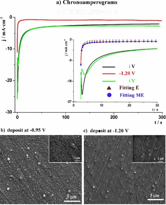
'· ' · ,, · • 1 µmFig. 8. a) Chronoamperograms of deposition processes obtained at 3 different potentials: -0.95 V- black curve, -1.20 V- red curve, -1.40 V- green curve, for 10 minutes. Inset represents first 30 seconds of Chronoamperograms, the brown triangles and blue circles represent fitting curves using Elovich and modified Elovich equations, respectively. 0.12 M Co(TFSI)2, T= 100 °C, WE-Pt dise, CE-Pt, RE-Ag/Ag20. b,c - SEM images of deposits obtained at -0.95V and -1.20V respectively.
data collected at -1.14 and -1.20V which present two semicircles, indicative of capacitive phenomena with fast and slow kinetics. Similar results have already been observed in the case ofBMPFAP IL, in which the second semicircle was ascribed to charge flow caused by the surface reconstruction (herringbone structures)[33,34].
At this juncture, it is worth mentioning that in pure EMimTFSI IL at 100 °C, the negative impedance and two capacitive semicircles were not observed in the wide potential range of its stability.
3.5. Potentiostatic electrodeposition
Having completed the fundamental studies on Co2+ reduc
tion, we would like now to check the influence of the reported phenomena on the synthesis of Co deposits. Potentiostatic depo sition at three different potentials (-0.95; -1.20 and -1.40V) for 10 min were performed on a Pt dise (Fig. 8a). The morphologies of obtained deposits were checked by SEM (Fig. 8b, c). The j-t curves obtained at -0.95 and -1.40V almost overlap from the beginning; divergence begins after 125 s, leading to different final current den sity values of j = 2.0 mA-cm-2 andj = 2.6 mA-cm-2, respectively. The
curve obtained at -1.20 V shows significantly smaller current den sity (0.95 mA-cm-2 at the end of the deposition), in agreement with
the CV curve, where at this potential a minimum of the current drop was reached. For the deposits taking place at-1.40 and-0.95 V, the j-t data reveal valleys during the first 25 s of deposition (Fig. 8
inset), which we believe to be associated to a 3D nucleation pro cess with diffusion controlled growth[35]. However in the case of the process at -1.20V. the current decreases drastically from the first seconds. The Elovich equation, commonly used to describe the chemisorption-like phenomena, has been used to fit the first thirty seconds of current profile obtained at -1.20V ( equation 7)[36].
dQ
- - = a . exp (b . Q)dt (7)
where a, b are fitting parameters and Qis the coverage ratio. Taking into account that Qo = 0 at t0 = 0 and Q = Qi, at t= tn (for n > 0), the
integrated form of equation 7 is:
Qi, =a'+ b' • (c + tn) (8)
where a', b' and c are the new fitting parameters. We have assumed that the current is driven by the coverage ratio of an "adsorption
like" phenomenon, so that the concentration of cobalt species in the vicinity of the electrode is constant (the current is not limited by the diffusion phenomenon, which is justified since the deposi tion current at -1.20 V is much smaller than at -0.95 V). The current equation can be written as:
j = -ddQdt (9)
where d is the proportionality constant. So the derived equation takes the form:
. A
J = B+t (10)
where A and B are the new fitting parameters. The brown triangle curve on the inset (Fig. Sa) represents the fitting with equation 1 O. A considerable difference between fit and experimental data is observed; the fit curve tends toj = 0 as t---,. ex, while the experimental data tends to lil = li,xol that is higher than O. The reason for such a difference most likely lies in the fact that the Elovich equation sol el y describes pure adsorption phenomena. Therefore, we found that a decent fit (R2 = 0.991) could be achieved (Fig. 8a, inset- blue circles)
by inserting an additional parameter icx to equation 10, representing
the non-zero current also called the leakage current. Thus using equation (11 ), we could nicely simulate for short deposition times, the experimental results with the parameters as follows: A= -1.90 mC-cm-2, B=-2.46 s andj00 =-0.71 mA-cm-2.
. A .
( )
J = B + t + Joo 11
Such a correlation suggests that the blocking of the reduction originates from drastic changes in the initial native double layer. For times greater than 30 s, the fitting is no longer valid since an increase in current density is observed, unlike the Elovich equation prediction. This is indicative of the perturbation of the "adsorption" phenomenon by the morphology of the deposited film.
The obtained deposits at -0.95 and -1.20 V were shiny and very adhesive, unlike the one at -1 .40 V which detached once the sub strate was removed from the solution. ln both cases, they consist of a thin layer made of parti cl es ranging from 20 to 100 nm on top of which we could visualize largely dispersed 500 nm to 1 µ.m size par ti cl es (Fig. 8b, c). Lastly, the cracks/scratches observed through our deposits are simply coming from the morphology of the substrate.
4. Discussion
We have reported that the reduction mechanism of Co2+ in ionic
liquid media is rather complex, dependent on many parameters and displaying unusual behavior such as: i) sudden drop in reduction current density at -1.2V, ii) reduction peak on the oxidation sweep, iii) current profile following the Elovich law, and iv) existence of tricky charge motions as deduced from the negative impedance and the delicate balance between two capacitive semicircles.
First of ail, we should recall that the double layer of pristine Ionie liquids in contact with a metal surface is highly structured, especially under additional polarization (Graph la, b) where the oscillatory like concentration profiles of cations and anions were observed experimentally and theoretically[ 13, 14, 161- Now, a legit imate question deals with the localization of the cobalt species depending upon concentration, a pp lied potential and so on. We will consider two different scenarios enlisting 1) an uniform distribu tion of the [ Co(TFSib J- complex throughout the double layer, hence disturbing its structure (diffusion of [Co(TFSI)3J- complex with out any obstacle) -Graph le, 2) the exclusion of the [Co(TFSlbJ complexwithin the compact layer of the double layer structure ( dif fusion of [Co(TFSlbl- occurs through the compact layer) -Graph 1 d. Next, we are trying to decide which of these proposed scenar ios is the most likely to be in agreement with our experiments and
existing literature so as to better understand the electrochemical electrodeposition of Co in ionic liquid media, and further try to extend it to other systems.
From the EQCM results, we have a straightforward evidence for an "accumulation" of [ Co(TFSib 1- complex during the current den sity drop and further its spontaneous consumption on the reverse sweep (leading to very sharp reduction peak). This is in agree ment with our IS spectra that showed the negative impedance in the potential range of sud den current density drop (-1.1 /-1.2 V), correlated with the negative slope on the polarization curve. Such behavior is related to the inhibition of the electrochemical process at the electrode as it was already investigated by other groups in aqueous solution[37I and more recently in IL[37,38I. The inhibition may be caused by many different phenomena such as: desorption of electrochemically active species, creation of passive layer, adsorp tion of surfactant or changes in double layer structuration. Further, the appearance of an oscillating current profile at fixed potential (-1.16 V) suggests an alternative transition between two antago nistic metastable states having highly different kinetics[32,37-39I. Additionally, as investigated by impedance spectroscopy during the current drop phenomenon, a second capacitive semicircle occurred (at low frequencies) that could be assigned to slow surface recon struction, as for example formation of herringbone structures, although th ose structures were found only at single crystal oriented electrodes[33,34I. Furthermore, chemisorption-like phenomena are consistent with the current profile of potentiostatic deposition at -1.20 V, which could be well fitted with the modified Elovich equation. Ali these results suggest that strong interactions between the electrode and the electrolyte occur, which is believed to be linked to the creation of a reversible energetic barrier related to the reconstruction of the double layer upon applied potential.
We also found that the nature of the Ionie Liquid cations as well as the charge of the cobalt complex strongly affect the exist ence and amplitude of the current density drop. More specifically, the current density drop is very clear when either the cation of IL is based on the ring structure with delocalized electrons (imid azolium based cation) or that the cobalt complex is negatively charged. To the extreme, this drop weakens or even disappears for IL based either on pyrrolidinium or ammonium cations and when positively charged cobalt complex is present. As those two parameters are the major ones influencing on the structure of the double layer, it is becoming doubtful that the scenario 1 (Graph 1 c) does occur; indeed the changes in double layer would not affect the state of the [Co(TFSlbJ- complex. However it would have tremen dous impact in scenario 2. With an increase in negative polarization ( decrease in potential ), the concentration of anions in the first layer of the double layer decreases, because of the electrostatic repul sion. As a consequence, the created cations layer moves towards the electrode surface (thinning of the layer) and finally the double layer gets more structured (e.g. higher number of layers) and com pact ( Graph 1 b ). This leads to an increase in both the high potential damping and the viscosity nearby the interface. Those changes can highly affect the electrochemical process taking place at the elec trode by disturbing both [Co(TFSI)31- diffusion and charge transfer in scenario 2. Additionally, because of its negative charge, the cobalt complex will sit on the second layer (negative charge layer); thus a first cation layer stands as a barrier hindering cobalt from being reduced. Once the charge of the cobalt complex is changed to posi tive, thanks to the migration flux, it can be directly incorporated in the first layer resulting in the lack of current drop. Overall, taking into account ail the above statements, we believe that the ener getic barrier at -1.20 V concerns the restructuring of the double layer under applied potential.
Now, it remains to explain why the aforementioned barrier is clearer in imidazolium based ionic liquids. Baldelli et al. [18I
a)OCP b) Negative polarization
0®0
�
0
$0
@
0
000@
0
@
(!)ê
0
00
@
0
Pt
@
0
@
Pt
j
®
0
oo
@
e
0
®
0
00
°
@0
®
00
�
@
0
œ@
e
e
®
@e
®
c) 1 d) 2:
0
1
0
Pt
Pt
!
®®
0
@
®
0
0®
0
0
®
®
TL cation [Co(TFSlhJ- complexe
IL anionreaction plane compact layer thickness
Graph 1. Draft of the double layer, top part in pure EMlmTFSI IL at a) OCP and b)under negative polarization, bottom part-2 possibilities of double layer in EMlmTFSI containing [Co(TFS1)31- complex under negative polarization c) totally changing the structure of double layer, d) being incorporated in the pristine structure of double layer.
perpendicular to cofacial versus the substrate surface as the neg ative polarization increases, due to its delocalized positive charge. Consequently, it produces more compact layer (as illustrated on
Graph 1 b ), highly inhibiting the reaction rate. However, this still does not explain the increase in current below -1.2 V since accord ing to this theory, the current should drop continuously and not exhibit a minimum as it is visible on the CVs curve. The actual charge transfer reaction plane (place where the electron exchange hap pens) is not localized at the surface of the electrode but at a distance from it (on the magnitude of few angstroms, Graph 1a, b)[40]. As mentioned above with an increase in negative polarization, the first cation layer becomes thinner and doser to the substrate. Addition ally, in case of imidazolium cation based IL metal-pi interactions can occur so that finally the first cation layer becomes conductive and further reduction of [Co(TFSI)JJ- complex positioned on sec
ond layer, can take place. This phenomenon could explain the very low adhesion of the deposit obtained at -1.40 V, as a layer of IL cations remains between the substrate and deposit. It would also justify the decrease in oxidation efficiency when the reverse sweep is chosen below the barrier phenomenon (SI, Fig. 1 *). The mecha nism of the electron transfer at low and high potentials due to the change in double layer is probably very different; more sophisti cated experiments must be performed to probe the validity of this statement. Lastly, it should be noted that in both potential ranges -1.0/-1, 1 V and -1.3/-1.4 V, the reaction limiting parameters are the same since the current values are very similar. On the other hand, if the phenomena are purely caused by surface reconstruction, as in the formation of herringbone structures, the further increase in current would be attributed to the instability of such structures at lower potentials[33 ].
Another important aspect is the dynamics of this phenomenon. We found that the energetic barrier ( minimum of the current drop) shifts to more negative values with an increase in the scanning rate
(SM, Fig. 10*), suggesting that it is a rather slow phenomenon (in the range of few seconds). Furthermore, the negative loop observed in impedance spectra is visible at frequencies as low as 0.15 Hz. This is in agreement with previous statements on the origin of the bar rier since the changes in the structure of the double layer, which is governed by ion transfer, do not occur rapidly. This can also justify the difference in CV shapes between RT and 100 °c in EMimTFSI IL. At low temperatures, the barrier can actually be enhanced (strong interactions between ions and the substrate), while the recons tructions slowed down (high viscosity/low conductivity); so that only one reduction peak appears at very low potentials during the first scan.
It must be recalled that this is not the only system within which the current suddenly drops leading to a split of the reduction waves or/and the reduction peak on oxidative sweeps. When Co2+ cations
are substituted with Mn2+ , we experienced the same phenomena, though shifted to more negative potentials (Fig. 9b). With Ni2+
cations, we solely observe a reduction peak on the reverse sweep (Fig. 9c). Finally, for Zn2+ cations, neither a drop in current nor the reduction on the reverse sweep (although some small valleys are present) are visible (Fig. 9d). However, the barrier phenomenon for Zn2+ system was clearly visible in Ionie Liquid containing stronger complexing anions EMimDCA[ 41 ], as studied by Forsytch et al. [ 42 ]. Baldelli et al. [18] claimed thatthe BMimdca IL creates a more struc tured double layer than EMimTFSI (with higher amount of layers that were ascribed to strong coordinating ability of DCA-); addi tionally, the viscosity of this IL (19.8 cp) is much smaller than EMimTFSI (34 cp), so that this phenomenon could be observed already at RT. In ail cases, the imidazolium cation and negatively charged metal complex are present, therefore there are still other parameters to be considered. Among them, the complex strength may be an important parameter as the DCA- is a much stronger complexing agent than TFSI- (difference in reduction of Zn2+ in
"s
0j
-2-�
-4 -6 -8 -10"s
0 " � -1-�
-2 -3 -4"s
0 " -1 -2 -3"s
0j
-2 -4 -6 a) Co(TFSI)2 -2.0 b) Mn(TFSI)2 current -2.0 c) Ni(TFSI)2 -2.0 d) Zn(TFSI)2 -2.0 -1.5 "·, Reduction peak on reverse sweep -1.5 -1.5 Reduction peak on reverse1 sweep??? ' -1.5 -1.0 --0.5 -1.0 --0.5 "-,Reduction peak on reverse sweep -1.0 -0.5 -1.0 --0.5 E vs (Ag/Ag,0) / V Fig. 9. CV curves of EMimTFSI solution at 100 °C containing: a) 0.12 M Co(TFSih, b) 0.12M Mn(TFSI),, c) 0.12M Ni(TFSI)2, d) 0.12M Zn(TFSI)2. WE-Ptw, CE-Pt, RE-Ag/Ag20, scanning rate 5 mv-s-1•both IL). The charge density of the complex (the relative charge taking into account the size of the complex) may also be a signifi cant issue. Other systems such as Mn(TFSI)z in BMPDCA[ 41 ], PdCI2 in BMimCl[43] and BMPDCA[44], NiCl2 in BMPDCA[44], or Zn(TfO) in BMPTf0[45] also exhibit uncommon CV curves. Sorne authors suggest that the two reduction peaks are due to the existence of 2 different metal complexes. This might be true in systems where the metal sait and IL have different anions; it becomes doubtful in our systems where both anions are the same, namely TFSI-. Addition ally it is not limited to divalent metallic cations since in a solution of TaF5 in BMPTSI, EMimTFSI and PMimTFSI ILs similar behavior was observed[46].
Although we suspect that the uncommon shape of the CV curve is due to double layer reconstruction, we still do not know what exactly its origin is or how the different metal cation complexes affect it. More detailed experimental work is needed on this topic as well as theoretical modeling, both are ongoing.
5. Conclusions
We have reported detailed studies on the reduction of Co2+ cations in Ionie Liquid media at elevated temperatures, based on the Electrochemical Quartz Crystal Microbalance, Cyclic Voltammetry, Chronoamperometric, Impedance Spectroscopy, Scanning Electron Microscopy and UV-Vis Spectroscopy experiments. An uncommon shape of the CV curve during reduction has been spotted with the sudden current density drop reaching its minimum at -1.2 V and
well defined reduction peak on the reverse sweep. We think this effect to be rooted in the creation of a reversible energetic bar rier that prevents from Co2+ reduction. By a precise adjustment of different bath parameters (substrate, IL formulation, Co2+ com plexation), we found that this phenomenon greatly depends on the nature of the ionic liquid cation and the charge of metal complex although other parameters such as the strength of the cation-anion interaction within the metal complex together with the electronic delocalization should be considered as well. Therefore, we believe that this barrier is nested in the reconstruction of the double layer under applied polarization. Such a phenomenon is not specific to the reduction of Co2+ in EMimTFSI IL since we show herein that it occurs as well for Mn2+, Ni2+ cations white it has already been reported for Zn2+, Pb2+, and Pd2+.
Finally, the paper shows the importance of tuning precisely the bath solution and specifically the ionic liquid formulation to grow deposits having the desired properties (such as good adhesion) which could find applications within the field of batteries, pho tovoltaic and microelectronics. We hope this better understanding of the double layer structuring, when working with ionic liquids, will help the community in harvesting ail the advantages that ionic liquid media present.
Acknowledgment
The authors thank P. Simon for fruitful discussions as well as to ALISTORE European Research Institute for the financial support to conduct the research.
Appendix A. Supplementary data
Supplementary data associated with this article can be found, in the online version, at http://dx.doi.org/10.1016/j.electacta. 2014.03.042.
References
[ 1]A.A. Aal, R. Al-Salman, M. Al-Zoubi, N. Borissenko, F. Endres, O. Hiifft, A. Prowald, S. Zein El Abedin, Interfacial electrochemistry and electrodeposition from some ionic liquids: In situ scanning tunneling microscopy, plasma electrochem
istry, selenium and macroporous materials, Electrochimica Acta 56 (2011) 10295-10305.
[2]F. Endres, O. Hiifft, N. Borisenko, L.H. Gasparotto, A. Prowald, R. Al-Salman, T. Carstens, R. Atkin, A. Bund, S. Zein El Abedin, Do solvation la y ers of ionic liquids influence electrochemical reactions? Physical Chemistry Chemical Physics 12 (2010) 1724-1732.
[3]F. Endres, S. Zein El Abedin, Air and water stable ionic liquids in physical chem istry, Physical Chemistry Chemical Physics 8 (2006), 2101-2016.
[4]W. Freyland, C.A. Zell, S. Zein El Abedin, F. Endres, Nanoscale electrodeposition of metals and semiconductors from ionic liquids, Electrochimica Acta 48 (2003) 3053-3061.
[5]P. Hapiot, C. Lagrost, Electrochemical Reactivity in Room-Temperature Ionie Liquids, Chemical Reviews 108 (2008) 2238-2264.
[6]W. Simka, D. Puszczyk, G. Nawrat, Electrodeposition of metals from non aqueous solutions, Electrochimica Acta 54 (2009) 5307-5319.
[7]Y.-Z. Su, Y.-C. Fu, Y.-M. Wei, J.-W. Yan, B.-W. Mao, The Electrode/Ionie Liquid Interface: Electric Double Layer and Meta! Electrodeposition, ChemPhysChem 11 (2010) 2764-2778.
[8]Y. Chen, C. Davoisne,J.-M. Tarascon, C. Guéry, Growth ofsingle-crystal copper sulfide thin films via electrodeposition in ionic liquid media for lithium ion batteries, Journal of Materials Chemistry 22 (2012) 5295-5299.
[9]Y. Chen, J.-M. Tarascon, C. Guéry, Exploring sulfur solubility in ionic liquids for the electrodeposition of sulfide films with their electrochemical reactivity toward lithium, Electrochimica Acta 99 (2013) 46-53.
[10] E. Azaceta, R. Marcilla, D. Mecerreyes, M. Ungureanu, A. Dev, T. Voss, S. Fantini, H.-j. Grande, G. Cabanera, R. Tena-Zaera, Electrochemical reduction of02 inl
butyl-1-methylpyrrolidinium bis(trifluoromethanesulfonyl)imide ionic liquid containing zn2• cations: deposition of non-polar oriented Zn0 nanocrystalline films, Physical Chemistry Chemical Physics 13 (2011) 13433-13440. [ 11] E. Azaceta, S. Chavhan, P. Rossi, M. Paderi, S. Fantini, M. Ungureanu, O. Miguel,
H.-j. Grande, R. Tena-Zaera, Ni0 cathodic electrochemical deposition from an aprotic ionic liquid: Building metal oxide n-p heterojunctions, Electrochimica Acta 71 (2012) 39-43.
[ 12] M. Tulodziecki, ].M. Tarascon, P.L. Ta berna, C. Guéry, Electrodeposition Growth of Oriented ZnO Deposits in Ionie Liquid Media, Journal of The Electrochemical Society 159 (2012) D691-D698.
[13] F. Endres, N. Borisenko, S. Zein El Abedin, R. Hayes, R. Atkin, The interface ionic liquid(s )/electrode(s ): In situ STM and AFM measurements, Faraday Discussions 154 (2012) 221-233.
[14] C. Merlet, B. Rotenberg, P.A. Madden, P.-L. Taberna, P. Simon, Y. Gogotsi, M. Salanne, On the molecular origin of supercapacitance in nanoporous carbon electrodes, Nature Materials 11 (2012) 306-310.
[15] H. Zhou, M. Rouha, G. Feng, S.S. Lee, H. Docherty, P. Fenter, P.T. Cummings, P.F. Fulvio, S. Dai,]. McDonough, V. Presser, Y. Gogotsi, Nanoscale Perturbations of Room Temperature Ionie Liquid Structure at Charged and Uncharged Interfaces, ACS Nana 6 (2012) 9818-9827.
[16] S. Baldelli, lnterfacial Structure of Room-Temperature Ionie Liquids at the Solid-Liquid Interface as Probed by Sum Frequency Generation Spectroscopy, The Journal of Physical Chemistry Letters 4 (2013) 244-252.
[17] T. Carstens, R. Hayes, S. Zein El Abedin, B. Corr, G.B. Webber, N. Borisenko, R. Atkin, F. Endres, In situ STM, AFM and DTS study of the interface 1-hexyl-3-methylimidazolium tris(pentafluoroethyl)trifluorophosphate/Au{l 11 ), Elec trochimica Acta 82 (2012) 48-59.
[18] S. Baldelli, Surface Structure at the Ionie Liquid-Electrified Meta! Interface, Accounts ofChemical Research 41 (2008) 421-431.
[19] N. Pradhan, T. Subbaiah, S.C. Das, Effect of Zinc on the Electrocrystallization of Cobalt, Journal of Applied Electrochemistry 27 (1997) 713-719.
[20] S.P. Jiang, A.C.C. Tseung, Reactive Deposition of Cobalt Electrodes, Journal of Electrochemical Society 137 (1990) 3387-3393.
[21] Y. Katayama, R. Fukui, T. Miura, Electrodeposition of Cobalt from an Imide Type Room-Temperature Ionie Liquid, Journal of The Electrochemical Society 154 (2007) D534-D537.
[22] R. Fukui, Y. Katayama, T. Miura, The effect of organic additives in electrode position of Co from an amide-type ionic liquid, Electrochimica Acta 56 (2011) 1190-1196.
[23] C. Su, M. An, P. Yang, H. Gu, X. Guo, Electrochemical behavior of cobalt from 1-butyl-3-methylimidazolium tetrafluoroborate ionic liquid, Applied Surface Science 256 (2010) 4888-4893.
[24] S. Schaltin, P. Nockemann, B. Thijs, K. Binnemans, J. Fransaer, Influence of the anion on the electrodeposition of cobalt from imidazolium ionic liquids, Elec trochemical and Solid-State Letters 10 (2007) D104-D107.
[25] M.A. Saito,].W. Moffett, Complexation of cobalt by natural organic ligands in the Sargasso Sea as determined by a new high-sensitivity electrochemical cobalt speciation method suitable for open ocean work, Marine Chemistry 75 (2001) 49-68.
[26] K. Fujii, T. Nonaka, Y. Akimoto, Y. Umebayashi, S.-i. Ishiguro, Solvation Struc tures of Sorne Transition Metal(Il) Ions in a Room-Temperature Ionie Liquid, 1-Ethyl-3-methylimidazolium Bis( trifluoromethanesulfonyl )amide, Analytical Sciences 24 (2008) 1377-1380.
[27] Y. Sugawara, T. Okayasu, A.P. Yadav, A. Nishikata, T. Tsuru, Dissolution Mech anism of Platinum in Sulfuric Acid Solution, Journal of The Electrochemical Society 159 (2012) F779-F786.
[28] S. Bruckenstein, M. Shay, Experimental Aspects of Use of the Quartz Crystal Microbalance in Solution, Electrochimica Acta 30 ( 1985) 1295-1300.
[29] L.-S. Liu, ]. Kim, S.-M. Chang, G.]. Chai, W.-S. Kim, Quartz Crystal Microbal ance Technique for Analysis of Cooling Crystallization, Analytical Chemistry 85 {2013) 4790-4796.
[30] G. Sauerbrey, Verwendung von Schwingquarzen zur Wagung Dunner Schichten und zur Mikrowagung, Zeitschrift für physik 155 (1959) 206-222.
[31] A. Bund, O. Schneider, V. Dehnke, Combining AFM and EQCM for the in situ
investigation of surface roughness effects during electrochemical metal depo sitions, Physical Chemistry Chemical Physics 4 (2002) 3552-3554.
[32] M.T.M. I<oper, Non-linear phenomena in electrochemical systems, Journal of the Chemical Society, Faraday Transactions 94 ( 1998) 1369-1378.
[33]R. Atkin, N. Borisenko, M. Drüschler, S. Zein El Abedin, F. Endres, R. Hayes, B. Huber, B. Roling, An in situ STM/AFM and impedance
spectroscopy study of the extremely pure 1-butyl-1-methylpyrrolidinium tris(pentafluoroethyl)trifluorophosphate/Au(l 11) interface: potential depend ent solvation layers and the herringbone reconstruction, Physical Chemistry Chemical Physics 13 (2011) 6849-6857.
[34] M. Drüschler, N. Borisenko,J. Wallauer, C. Winter, B. Huber, F. Endres, B. Roling, New insights into the interface between a single-crystalline metal electrode and an extremely pure ionic liquid: slow interfacial processes and the influence of temperature on interfacial dynamics, Physical Chemistry Chemical Physics 14 (2012) 5090-5099.
[35] E.L. Smith, J.C. Barron, A.P. Abbott, K.S. Ryder, Time Resolved in Situ Liquid Atomic Force Microscopy and Simultaneous Acoustic Impedance Electrochem ical Quartz Crystal Microbalance Measurements: A Study of Zn Deposition, Analytical Chemistry 81 (2009) 8466-8471.
[36] F.-C. Wu, R.-L. Tseng, R.-S.Juang, Characteristics ofElovich equation used for the analysis of adsorption kinetics in dye-chitosan systems, Chemical Engineering Journal 150 (2009) 366-373.
[37] 1.2. Kiss, V. Gâspâr, Stability Analysis of the Oscillatory Electrodissolution of Copper with lmpedance Spectroscopy, The Journal of Physical Chemistry A 102 (1998) 909-914.
[38] S. Schaltin, I<. Binnemans, J. Fransaer, Oscillating electrochemical reaction in copper-containing imidazolium ionic liquids, Physical Chemistry Chemical Physics 13 (2011) 15448-15454.
[39] A. Survila, Z. Mockus, R. Juskenas, Current oscillations observed during code position of copper and tin from sulfate solution, Electrochimica Acta 43 {1998) 909-917.
[40] A.A. Franco, P. Schott, C.Jallut, B. Maschke, A Dynamic Mechanistic Madel ofan Electrochemical Interface, Journal ofThe Electrochemical Society 153 (2006) A1053-A1061.
[41] M.-J. Deng, P.-Y. Chen, T.-1. Leang, 1.-W. Sun,J.-K. Chang, W.-T. Tsai, Dicyanamide anion based ionic liquids for electrodeposition of metals, Electrochemistry Communications 10 (2008) 213-216.
[42] T.]. Simons, A.A.]. Torriero, P.C. Howlett, D.R. Macfarlane, M. Forsyth, High current density, efficient cycling of Zn2• in 1-ethyl-3-methylimidazolium dicyanamide ionic liquid: The effect ofzn2• sait and water concentration, Elec trochemistry Communications 18 (2012) 119-122.
[43] M. Jayakumar, I<.A. Venkatesan, T.G. Srinivasan, P.R. Vasudeva Rao, Electro chemical behavior of ruthenium (Ill), rhodium (Ill) and palladium (Il) in 1-butyl-3-methylimidazolium chloride ionic liquid, Electrochimica Acta 54 (2009) 6747-6755.
[44] H.-Y. Huang, P.-Y. Chen, Voltammetric behavior of Pd{Il) and Ni{Il) ions and electrodeposition of PdNi bimetal in N-butyl-N-methylpyrrolidinium dicyanamide ionic liquid, Electrochimica Acta 56 (2011) 2336-2343.
[45] Z. Liu, A. Prowald, S. Zein El Abedin, F. Endres, Template-assisted electrode position of highly ordered macroporous zinc structures from an ionic liquid, Journal of Solid State Electrochemistry 17 (2013) 1185-1188.
[46] A. Ispas, B. Adolphi, A. Bund, F. Endres, On the electrodeposition of tantalum from three different ionic liquids with the bis(trifluoromethyl sulfonyl) amide anion, Physical Chemistry Chemical Physics 12 (2010) 1793-1803.