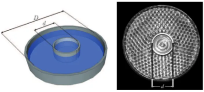
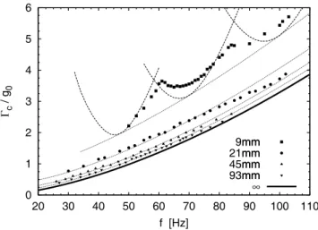
Effect of a capillary meniscus on the Faraday instability threshold
Texte intégral
Figure

Documents relatifs
1462 A common origin for E mutations in different species experimental mice analyzed expressed detectable levels of Ea RNA, with the exception of mice of the w301 haplotype.. The
Acoustic resonances have been observed in single crystals of yttrium iron garnet (YIG), gallium-substi- tuted YIG, magnesium ferrite, cobaIt ferrite, a series of
In the meantime, Zakharov and Filonenko [4] showed, in the case of four-wave interactions, that the kinetic equations derived from the wave turbulence analysis have exact
We observed that the dynamic variation of absorption measured at the maximum sensitivity wavelength [maximum of the optical absorption change (OAC) of Figure 10a] is greater in 50TiO
Chirurgie Générale Neurologie Neuro-chirurgie Radiologie Chirurgie Cardio-vasculaire Rhumatologie Neuro-chirurgie Anesthésie Réanimation Anesthésie Réanimation Anatomie
Correlations between neighboring particles depend on the their residence time in the same turbulent eddy compared to their response time [20]. Such a residence time relies on
The current stock of retrieved cores and data from borehole logging and experi- ments offers tantalizing glimpses of several processes, including how crust is generated, or
The proposed distributed algorithm uses p-hop neighbor information to identify critical head robots that can direct two neighbors to move toward each other and bi-connect
