Faculté de génie
Département de génie civil
BOND PERFORMANCE BETWEEN CONCRETE
AND THE FRP TUBE UNDER CYCLIC LOADING;
AND DESIGN OF NEW BEAM-COLUMN
CONNECTION FOR CONCRETE-FILLED FRP
TUBES
PERFORMANCE DE L’ADHÉRENCE ENTRE LE
BÉTON ET LE TUBE SOUS CHARGES LATÉRALES
CYCLIQUES, EN PRF ET CONCEPTION DE
NOUVELLES CONNEXIONS POUTRE-COLONNE
POUR TUBES EN PRF REMPLIS DE BÉTON
Thèse de doctorat
Spécialité : génie civil
Ahmed Mohamed Ahmed Ali
(Ahmed Ali)
A dissertation submitted in partial fulfilment of the requirements for the degree of
Doctor of Philosophy (Civil Engineering)
Sherbrooke (Québec) Canada
Novembre 2018
MEMBRES DU JURY
Prof. RADHOUANE MASMOUDIDirecteur
Prof. MOHAMMAD IQBAL KHAN Évaluateur
Prof. RICHARD GAGNÉ Rapporteur/Évaluateur
Prof. SLIMANE METICHE Évaluateur
Prof. HAMDY MOHAMED Évaluateur
DEDICATION
To My Father’s Soul, Who Taught Me How to Be an Honest,
Sincere, Ambition Person, He Is the Reason for Who I Am Now and
ABSTRACT
In the last two decades, researchers reported that concrete-filled FRP tube (CFFT) members have a better performance compared to conventional reinforced concrete members (beams or columns) in terms of strength, ductility, and durability in corrosive environments. This superior performance of CFFT returns to many reasons like, the FRP tube provides a longitudinal and transverse reinforcement, serve as a permanent lightweight formwork, and confine the concrete core which increases the concrete compressive strength and provides more ductility for the CFFT structural members. All these advantages provide CFFTs the ability to be used in many structure field applications like marine piles, bridges girders and columns, poles, and overhead sign structures.
Protracted studies are conducted to investigate and evaluate the behavior of CFFT structural members under different type of loading, lateral monotonic or cyclic loads with or without axial loads. Nevertheless, rare researches were investigated the effect of the bond between the concrete core and the FRP tube on the flexural capacity of the CFFT member. The size effect of the FRP tube also needs to be examined.
In addition, this thesis also aimed at answering another question: how to connect CFFT beam to CFFT column? up-to-date, all the previous researches in CFFT domain are studied CFFT beams or CFFT column and there are no previous trials to establish a CFFT beam-column connection.
This thesis is divided into two parts. The first part investigates the interfacial bond performance between the FRP tube and the concrete core. Full-scale specimens were tested under lateral cyclic load. An innovative approach was proposed to assess the bond between the FRP tube and the concrete core by using embedded concrete strain gauges into the concrete core, to study the composite action between the FRP tube and its concrete core effect on the flexural behavior of CFFT. In addition, contribution of sand coating bond enhancer on improving the bond between the FRP tube and the concrete core is also investigated. Four full scale circular CFFT columns were tested in the first part under lateral
cyclic load only to study the bond between the FRP tube and the concrete core, sand-coating effect (two columns have sand-coating and the other two are without) and the tube-size effect (two columns have 305 mm diameter and the other two have 406 mm diameter) on the flexural behaviour of the CFFT members. An analytical model was developed to predict the flexural behavior of the fully bonded CFFT members. This model was established based on layer-by-layer section analysis. The model predicted the failure mode, flexural capacity, curvature, and compression zone depth.
While the second part focused on development and design of a new assembly of CFFT beam-column connection for rectangular CFFT members. The new connection has been studied experimentally, and a new analytical model to predict its structural capacity is proposed. This part also proposes design equations and analytical study to calculate the flexural capacity of rectangular CFFT beams as well as the required embedded depth to achieve its flexural capacity. Four rectangular CFFT beam-column connections were designed, manufactured, assemblage and tested under monotonic load.
The first part results illustrated that the bond significantly influences the flexural strength and stiffness of the CFFT column. Using sand-coating as a bond enhancer improved the bond between the FRP tube and the concrete core, minimize the adverse effect of the interface gap, and increased the flexural capacity and stiffness of tested CFFT columns. This study provides some recommendations required to use unreinforced CFFT members to attain its structural benefits like using non-shrink concrete in the filling the FRP tube is suggested to eliminate generating of the interface gap. In addition, sand-coating or any comparable bond enhancer should be utilized to improve the interfacial bond between the concrete core and the FRP tube. These recommendations are demanded to realize the full composite action in the unreinforced CFFT members. The proposed analytical model estimated the failure mode, flexural capacity, curvature, and compression zone depth with a good agreement comparing by the experimental results.
The second part results showed that the proposed connection successfully transferred the moment from the CFFT beam to the CFFT column. The optimal embedded depth required to induce flexural failure of the CFFT beam is two times the CFFT beam depth (i.e. FRP
tube depth). The proposed theoretical model successfully predicted the flexural strength of the CFFT beam, the failure mode, the optimal embedded depth, and the effect of the embedded depth on the flexural capacity of the connection with high accuracy (maximum difference 10.5%).
Keywords: Fiber-reinforced polymer, Concrete-filled FRP tubes, Cyclic loading, Bond,
Composite action, shrinkage gap, Sand-coating, Interface gap, Flexural behavior, CFFT connection, Beam-column connection, Embedment depth.
RÉSUMÉ
Au cours des deux dernières décennies, les travaux de recherche rapportés sur les tubes de polymères renforcés de fibres remplis de bétons (TPRFB) ont clairement démontré une meilleure performance par rapport aux éléments (poutre ou colonne) en béton armé conventionnel : en termes de résistance, ductilité et durabilité dans des environnements corrosifs. Plusieurs facteurs expliquent cette performance supérieure : le tube en (PRF) fournit un confinement parfait pour le béton, particulièrement lorsqu’il est sollicité en traction, fournit également des renforts dans les deux directions longitudinale et transversale de l’élément, et sert de coffrage léger et permanent. La résistance à la compression du noyau de béton est considérablement augmentée et la ductilité/déformabilité des membrures se trouve grandement améliorée. Tous ces avantages confèrent la possibilité aux (TPRFB) d'être utilisés dans de nombreuses applications telles que les pieux marins, les poutres et les colonnes de ponts, les poteaux et les structures de panneaux suspendus.
Plusieurs recherches ont été menées pour étudier et évaluer le comportement des éléments structuraux (TPRFB) sous différents types de chargement : charges latérales monotones ou cycliques avec ou sans charges axiales. Néanmoins, très peu de recherches ont été réalisées pour étudier l'effet de l’adhérence entre le noyau de béton et le tube PRF sur le comportement à la flexion d’un élément TPRFB. L'effet de taille du tube en PRF doit également être examiné.
Par ailleurs, une question que la présente thèse a tenté de répondre est : comment attacher une poutre (TPRFB) à une colonne (TPRFB)? À la lumière de la revue de littérature et aux mieux de mes connaissances, il n’existe aucune étude traitant des connexions poutre/colonne pour TPRFB.
Cette thèse est composée de deux parties. La première partie porte sur l’évaluation de la performance de l’adhérence entre le tube en PRF et le béton. Des prototypes grandeur nature de colonnes TPRFB ont été testés sous charges latérales cycliques. Une approche novatrice pour évaluer la performance de l’adhérence entre le tube de PRF et le noyau de béton en utilisant des jauges de déformation intégrées dans le béton a été développée et utilisée. Cette
technique a permis d’étudier l'action composite entre le tube en FRP et le noyau de béton sur le comportement en flexion des colonnes TPRFB. En outre, la contribution de l'amélioration de l’adhérence à l’aide d’enrobage de sable est également étudiée, et est quantifiée. Quatre colonnes circulaires, grandeur nature, ont été testées dans la partie I sous charge cyclique latérale pour étudier l’adhérence entre le tube en PRF et le noyau de béton. L’effet d’un revêtement de sable (Deux colonnes avec revêtement de sable versus deux colonnes sans revêtement de sable), ainsi que l'effet de la taille des tubes (deux colonnes de 305 mm de diamètre versus deux autres de 406 mm de diamètre) sur le comportement en flexion des membres TPRFB ont été étudiés.
La deuxième partie a porté sur le développement et la conception d'une nouvelle connexion poutre-colonne pour TPRFB de sections rectangulaires. La nouvelle connexion a été étudiée expérimentalement, et un nouveau modèle analytique permettant de prédire sa capacité structurale est proposé. Des équations de conception et des études analytiques pour calculer la capacité en flexion de poutres rectangulaires de TPRFB, ainsi que la profondeur encastrée requise sont également présentées. Quatre connexions poutres-colonnes TPRFB de sections rectangulaires ont été conçues, fabriquées et testées sous charge monotone.
Les résultats de la première partie ont montré que l’adhérence influence significativement la résistance à la flexion et la rigidité de la colonne TPRFB. L'utilisation d’un revêtement de sable améliore l’adhérence entre le tube de PRF et le noyau de béton, minimise l'effet néfaste d’un retrait éventuel du béton. Cette étude fournit quelques recommandations nécessaires pour utiliser les membrures TPRFB non armées, comme l'utilisation d’un béton expansif dans le remplissage du tube en PRF, afin d’éviter toute possibilité de retrait du béton, particulièrement sous charge de flexion. De plus, l’utilisation d’un revêtement de sable ou toute autre technique pouvant améliorer l’adhérence entre le noyau en béton et le tube en PRF est nécessaire sous charge de flexion. Ces recommandations sont exigées pour réussir l'action composite complète dans les membrures TPRFB en béton non-armé.
Les résultats de la deuxième partie ont montré que la connexion proposée transfère avec succès le moment de la poutre TPRFB vers la colonne TPRFB. La profondeur optimale requise pour induire une rupture par flexion de la poutre TPRFB est évaluée à environ deux
fois la profondeur de la poutre TPRFB (c'est-à-dire deux fois la profondeur du tube en PRF de la poutre). Le modèle théorique proposé prédit avec succès et une bonne précision la résistance à la flexion de la poutre TPRFB, le mode de rupture, la profondeur optimale d’ancrage et l'effet de la profondeur encastrée sur la capacité en flexion de la connexion.
Mots clés : Polymère renforcé de fibres (PRF), Tubes en PRF remplis de béton, charge
cyclique, adhérence, Action composite, retrait du béton, revêtement de sable, comportement en flexion, connexion TPRFB, connexion poutre-colonne, profondeur d’ancrage.
LIST OF PUBLICATIONS
During this research project at the University of Sherbrooke, the candidate has produced the following publications:
JOURNAL PAPERS:
1. Ahmed, M. Ali and Radhouane Masmoudi. “Flexural strength and behavior of circular sand-coated concrete-filled FRP tubes under cyclic
load.” ACI Special Publication, SP-79, (2017), (Accepted and Under
Press).
2. Ahmed, M. Ali, Daniel Robillard, Radhouane Masmoudi, and Mohammad Khan. “Experimental investigation of bond and tube thickness effect on the flexural behavior of concrete-filled FRP tube under lateral cyclic loading.” Journal of King Saud University - Engineering Sciences,(2017), (Accepted and Under Press)..
3. Ahmed, M. Ali and Radhouane Masmoudi. “Experimental and analytical investigation of new concrete filled FRP tube beam-column connections”, Journal of Engineering Structures, Elsevier, (2018), (Submitted on 30 June 2018, Under review).
CONFERENCES PUBLICATIONS:
4. Ahmed, M. Ali, Radhouane Masmoudi, and Mohammad Khan. “Effect of sand-coating bond performance on the flexural capacity of circular
Mechanics and Materials, EMM608–(1–10), Canadian Society for Civil Engineering, Annual Conference – Vancouver, , (2017).
5. Ahmed, M. Ali and Radhouane Masmoudi. “Experimental Investigation of a New Beam-Column Connection for Concrete-Filled FRP Tubes
(CFFTs)”, 9th International Conference on Fiber-Reinforced Polymer
Acknowledgment
In the Name of Allah, the Most Gracious, the Most Merciful. All praise is for Allah, Lord of the Worlds. The Most Gracious, The Most Merciful. Master of the Day of Judgment. You (Alone) we worship, and You (Alone) we ask for help. Guide us to the Straight Way, the way of those upon whom You have bestowed Grace, not of those who earned Your Anger, nor of those who went astray (Al-Fatiha, The Holy Quran).
The author wishes to express his deep gratitude to everyone who contribute to make this research possible. The author also expresses his sincere gratitude and appreciation to his supervisor Dr. RADHOUANE MASMOUDI for his guidance, inspiration, and encouragement throughout this research program. Also, sincere thanks to Dr. M.-Iqbal Khan for his contributions to my journal and conference publications, and for accepting to review my thesis.
The author would like to thank the other jury members for accepting to review my thesis and I look forward for their valuable suggestions and comments.
Sincere words of thanks must also go to Dr Jean Proulx, the head of the Civil Engineering department in University of Sherbrooke, for his support. Special thanks are extended to Mr. Steven Maceachern, Mr. Sébastien Rioux, Mr. Claude Aubé, Mr. Nicolas Simard, and Mr. Laurent Thibodeau for their assistance during the experimental phases of this research. My sincere appreciation and thanks must be expressed to my family (my Mother, my Brothers, my Sisters) for their encouragements, endless love, unlimited bolster, and fascinating moments they’ve given me.
Words cannot express the author’s gratitude and appreciation towards his wife Zeinab for her understanding, encouragement, and support always. No one cannot imagine how much strength her support has given me during this challenging time. Thank you for your thoughtfulness, your words of encouragement, and being there for me through my ups and
downs. I would also like to thank my little daughter Toka, who always stole my heart with her brilliant smile; she is the joy of our lives.
Finally, this thesis is dedicated to the memory of my father, who has been a wonderful parent and has shown a genuine interest in and concern for my life, my work, and my well-being. To whom has sacrificed to give me the ability to do this work and reach this point. To whom I promised to dedicate this dissertation before he left this world, To my father.
Ahmed Ali
November 2018
TABLE OF CONTENTS
DEDICATION ... I ABSTRACT ... I RÉSUMÉ...V LIST OF PUBLICATIONS ... IX ACKNOWLEDGMENT ... XI TABLE OF CONTENTS ... XIII LIST OF TABLES ...XVII LIST OF FIGURES ... XIX1. INTRODUCTION ... 1
1.1. GENERAL BACKGROUND ... 1
1.2. RESEARCH ORIGINALITY AND CONTRIBUTION ... 2
1.3. RESEARCH OBJECTIVES ... 3
1.4. METHODOLOGY AND CONTENTS ... 4
2. LITERATURE REVIEW ... 7
2.1. INTRODUCTION ... 7
2.2. REVIEW ON CONCRETE-FILLED FRPTUBES (CFFT)PERFORMANCE ... 8
2.3. BOND IN CONCRETE FILLED FRPTUBES ... 16
2.4. CONCRETE FILLED FRPTUBES (CFFTS)CONNECTIONS ... 21
3. FLEXURAL STRENGTH AND BEHAVIOR OF CIRCULAR SAND-COATED CONCRETE-FILLED FRP TUBES UNDER CYCLIC LOAD ... 39
3.1. SYNOPSIS ... 40 3.2. INTRODUCTION ... 41 3.3. RESEARCH SIGNIFICANCE ... 42 3.4. EXPERIMENTAL PROGRAM ... 42 3.4.1. Material properties ... 42 3.4.2. Test specimens ... 43 3.4.3. Test setup... 46
3.4.4. Instrumentation and test procedure ... 48
3.4.4.1. Instrumentation ... 48
3.4.4.2. Test procedure ... 50
3.5. EXPERIMENTAL RESULTS ... 51
3.5.2. Flexural strength ... 55
3.5.3. Initial stiffness ... 56
3.5.4. CFFT measured column stiffness ... 56
3.5.5. Strain compatibility analysis ... 58
3.5.6. Slippage observation... 58
3.5.7. Embedded depth ... 60
3.6. CONCLUSIONS ... 61
4. INNOVATIVE APPROACH TO INVESTIGATE THE COMPOSITE ACTION OF FULL-SCALE CFFT COLUMNS UNDER CYCLIC LOAD ... 63
4.1. ABSTRACT ... 63 4.2. INTRODUCTION ... 64 4.3. EXPERIMENTAL PROGRAM ... 65 4.3.1. Material properties ... 65 4.3.1.1. FRP tubes ... 65 4.3.1.2. Concrete ... 67 4.3.1.3. Steel reinforcement ... 67 4.3.2. Preparation of specimens ... 67 4.3.2.1. Sand-coating procedure ... 67 4.3.2.2. Test Specimens ... 68
4.3.2.3. Assembling of the specimens ... 69
4.3.3. Test setup ... 70
4.3.4. Instrumentation and test procedure ... 73
4.4. EXPERIMENTAL RESULTS ... 75
4.4.1. Test observations ... 75
4.4.2. Failure mode ... 76
4.4.3. Hysteretic responses ... 77
4.4.4. Envelope load-displacement responses ... 81
4.4.5. Column-footing slippage ... 83
4.4.6. GFRP tube-concrete core slippage ... 83
4.4.7. Interior and exterior axial strains comparison ... 84
4.4.8. Curvature distribution over the column height ... 88
4.4.9. Moment-curvature responses ... 89
4.4.10. Hoop strains distribution over the column height ... 89
4.4.11. Initial stiffness and cracking moment ... 91
4.4.12. Dissipated energy and damping ratio ... 92
4.4.13. Residual displacement ... 93
4.5. DISCUSSION... 94
4.5.1. Composite action of CFFT columns ... 94
4.5.2. Effect of tube size on the interface gap size... 96
4.5.3. Effect of interface gap size ... 96
4.5.4. Effect of sand-coating ... 97
4.6. CONCLUSIONS AND RECOMMENDATIONS ... 97
5. ANALYTICAL MODEL TO ESTIMATE THE FLEXURAL BEHAVIOR OF THE FULLY-BONDED CFFT... 101
5.2. MATERIALS CONSTITUTIVE MODELS ... 101
5.2.1. FRP tube material model ... 101
5.2.2. Concrete material model ... 102
5.3. GEOMETRY OF THE CFFTCROSS-SECTION ... 104
5.4. EQUILIBRIUM OF INTERNAL FORCES AND MOMENTS ... 108
5.5. PROCEDURE OF ANALYSIS... 113
5.6 . VALIDATION OF THE MODEL ... 114
5.7 . CONCLUSIONS ... 116
6. EXPERIMENTAL AND ANALYTICAL INVESTIGATION OF NEW CONCRETE FILLED FRP TUBE BEAM-COLUMN CONNECTIONS ... 117
6.1. ABSTRACT ... 118 6.2. INTRODUCTION ... 119 6.3. EXPERIMENTAL PROGRAM ... 120 6.3.1. Material Properties ... 120 6.3.1.1. FRP Tubes ... 120 6.3.1.2. Concrete ... 121 6.3.1.3. Steel Reinforcement ... 121 6.3.1.4. Steel Connection ... 121 6.3.1.5. Epoxy Grout ... 122
6.3.2. Preparation and Description of the Test Specimens ... 122
6.3.3. Test Setup and Instrumentation ... 126
6.4. EXPERIMENTAL RESULTS AND DISCUSSIONS ... 128
6.4.1. Failure Mode ... 129
6.4.2. Load-Displacement Response ... 132
6.4.3. Moment Curvature Relationship ... 133
6.4.4. Curvature and Plastic Hinge ... 134
6.4.5. Connections Strength and Stiffness ... 134
6.4.6. Steel Connections and the CFFT Column ... 136
6.5. ANALYTICAL MODEL ... 137
6.5.1. Validation of the Analytical Model ... 142
6.6. CONCLUSIONS ... 143
7. ANALYTICAL STUDY OF THE PROPOSED CFFT BEAM-COLUMN CONNECTION ... 145
7.1. INTRODUCTION ... 145
7.2. MODEL WITH STRESS-BLOCK APPROACH ... 145
7.3. MODEL WITH LAYER-BY-LAYER APPROACH ... 147
7.3.1. Materials constitutive models ... 147
7.3.1.1. FRP tube material model... 147
7.3.1.2. Concrete material model ... 148
7.3.2. Equilibrium of internal forces and moments... 150
7.3.3. Procedure of analysis ... 152
7.3.4. Validation of the model ... 155
7.4. PARAMETRIC STUDY ... 156
7.4.2. Effect of the tube web-thickness ... 157 7.4.3. Effect of the beam depth ... 158 7.4.4. Effect of the beam width ... 158 7.4.5. Effect of the tube mechanical properties ... 160 7.4.6. Effect of the concrete compressive strength ... 160 7.4.7. Effect of the bond strength of the surrounding material ... 162
7.5. CONCLUSIONS ... 163
8. GENERAL CONCLUSIONS AND RECOMMENDATIONS ... 165
8.1. SUMMARY ... 165 8.2. CONCLUSIONS ... 165
8.2.1. First Part: Effect of Bond performance between the FRP tube and the concrete core on the flexural behavior of CFFT under cyclic load ... 165 8.2.2. Second Part: Design, Fabrication and Testing of New Beam/Column connection for CFFT rectangular structural members ... 167
8.3. RECOMMENDATIONS FOR FUTURE WORK ... 168
8.3.1. First Part ... 168 8.3.2. Second Part ... 169
8.4. CONCLUSIONS (EN FRANÇAIS) ... 170
8.4.1. Première partie : Évaluation de la performance de l’adhérence entre le tube en PRF and le noyau de béton ... 170 8.4.2. Deuxième Partie: Conception, fabrication et la mise à l’essai d’une nouvelle connexion poutre-colonne pour les membrures TPRFB de sections rectangulaires ... 172
8.5. RECOMMANDATIONS POUR DES TRAVAUX FUTURS ... 173
8.5.1. Première Partie: ... 173 8.5.2. Deuxième Partie: ... 174
LIST OF TABLES
Table 3-1: Material mechanical properties of GFRP tubes* ... 43 Table 3-2: Summary of the test specimens ... 45 Table 3-3: Summary of the test results ... 54 Table 4-1: Mechanical Properties of GFRP Tubes ... 66 Table 4-2: Columns details ... 69 Table 4-3: Experimental Results Summary ... 76 Table 6-1: Tubes mechanical properties ... 121 Table 6-2: Details of the specimens ... 125 Table 6-3: Test results ... 128 Table 6-4: Comparing the model results with the experimental results of SE-18 ... 142
LIST OF FIGURES
Figure 2.1: Normalized stress-strain curves for the effect of tube cross-section
(Mirmiran et al. 1998b). ... 9 Figure 2.2: Biaxial stress-strain curves for the effect of length to diameter ratio
(Mirmiran, et al. 1998a). ... 9 Figure 2.3: Moment–deflection curve for spin-cast and filament-wound CFFTS
(Mirmiran et al. 2000). ... 11 Figure 2.4: Details of GFRP tubes tested by (Fam et al. 2005). ... 12 Figure 2.5: Casting setup of CFFT beams tested by (Fam et al. 2005). ... 13 Figure 2.6: Specimens Details tested by (Fam et al. 2005). ... 13 Figure 2.7: Load-deflection behavior of tested beams by (Fam et al. 2005). ... 14 Figure 2.8: Variation of neutral axis of tested beams by (Fam et al. 2005). ... 14 Figure 2.9: Load-axial strain behavior of tested columns by (Fam et al. 2005)... 15 Figure 2.10: Failure mode of tested beams by (Fam et al. 2005). ... 15 Figure 2.11: Interior shear ribs of the FRP tubes (Mirmiran et al. 1998a). ... 17 Figure 2.12: Push-through Specimens (Nelson et al. 2008a). ... 18 Figure 2.13: Bond stress – slip behavior of push-through specimens (Nelson et al. 2008a). ... 19 Figure 2.14: Schematic of rib width, thickness, bay, and concrete teeth (Ji et al. 2009). ... 19 Figure 2.15: Beam configurations (Belzer et al. 2013). ... 20 Figure 2.16: Load deflection curves for beams (Belzer et al. 2013). ... 21 Figure 2.17: CFFTs connections studied by (Zhu 2004). ... 23 Figure 2.18: CFFT Column- footing connections studied by (Zhu 2004)(a): for precast
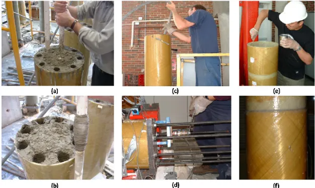
CFFT, (b): for post-tensioned CFFT, (c): for Cast-in-Place Columns. ... 23 Figure 2.19: Separation between FRP Tube and RC Footing (Zhu 2004). ... 24 Figure 2.20: Lateral Load-Deflection Envelope Curves of Tested Columns (Zhu 2004). ... 24 Figure 2.21: Specimen Casting and assembly: (a) PVC Pipes Being Pulled Out After
Partial Setting of Concrete, (b) Enlarged Ducts Made by PVC Pipes, (c) Consolidating Grout in Steel Bar Spliced CFFT Beam, (d) Post-Tensioning Procedure, (e) Applying Epoxy to Inside Surface of FRP Socket Spliced Beam, (f) Close-up View of FRP Socket
Spliced CFFT Beam Joint (Zhu 2004). ... 25 Figure 2.22: Comparison of load-deflection responses of CFFT beams (Zhu 2004) ... 26
Figure 2.23: First connection type: direct embedment of the precast CFFT into
the footing (Nelson et al. 2008a). ... 27 Figure 2.24: Second connection type: direct embedment of the precast CFFT into
the footing (Sadeghian et al. 2011). ... 27 Figure 2.25: Test Setup for the direct embedment precast CFFT into the footing
(Nelson et al. 2008a). ... 28 Figure 2.26: Failure mode: (a) fine cracks in the specimens with embedment lengths
equal to or greater than the optimal length (CFFT tension failure), (b) excessive slip/bond
failure in the specimens with embedment lengths smaller than the optimal length. (Lai 2010). ... 28 Figure 2.27: Effect of embedment length into footing on ultimate load capacity of CFFT
(Lai 2010). ... 29 Figure 2.28: Failure modes: (a) Bond failure of specimen 0.5D, (b) bond failure and hoop
fracture of tube in specimen 1.0D, (c, and d) tensile rupture failure of tube in specimens
1.5D and 2.0D respectively. (Lai 2010). ... 29 Figure 2.29: Responses of specimens with different RC stub lengths: (a) load-deflection;
(b) load-slip plus crack opening; (c) load-longitudinal strain at stub end (Sadeghian et al. 2011). . 30 Figure 2.30: Splice details (Helmi et al. 2005). ... 31 Figure 2.31: Test specimens (Zakaib and Fam 2012). ... 32 Figure 2.32: Failure Modes: (a) Tension slip and compression GFRP tube splitting in CS1
and CS2, (b) CFFT tension failure at end of steel section in CS3, (c) Excessive yielding of
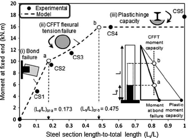
the steel in CS4 and CS5 (Zakaib and Fam 2012). ... 33 Figure 2.33: Load-deflection responses of cantilever specimens (Zakaib and Fam 2012). ... 34 Figure 2.34: Summary of the analytical model: (a) slip of steel section; (b) flexural failure
of CFFT at the end of steel section; (c) plastic hinge development at fixed end
(Zakaib and Fam 2012). ... 34 Figure 2.35: failure envelope based on different failure modes according to steel length
compared to experimental results (Zakaib and Fam 2012). ... 35 Figure 2.36: Description of the modular CFFT columns to show (a) formwork for
the CFFT segment, (b) manufactured segment, (c) epoxy application, and (d) installation
of the segment (Youm et al. 2013). ... 36 Figure 2.37: Lateral force–displacement envelope curves for the columns in: (a) S-series,
Figure 2.38: Failures at the plastic hinge zone for the columns: (a) FRP tube crack in specimen of S-MC (modular CFFT) column, (b) FRP tube diagonal cracks of S-CC (cast-in-place CFFT) column, (c) spalling of concrete cover of S-C (cast-in-place) column, (d) gap opening at the base of the column M-MC, (e) gap opening at the base in of the column M-CC, (f) buckling of longitudinal bars in the column M-C, (g) FRP tube rupture in the column L-MC, (h) longitudinal bar buckling after in the column L-M (modular RC column) and (i) the column L-C (cast-in-place RC)
column (Youm et al. 2013). ... 38 Figure 3.1: Specimen shape ... 44 Figure 3.2: Sand-coating Process ... 44 Figure 3.3: Specimen preparation, (a): Establish of the steel holder with the embedded
strain gauges and wood end-plate., (b) and (c): inserting of the steel holder inside the tube and the strain gauges aligned with north and south of the specimen, and
(d): Inserting of the column into the footing steel cages. ... 46 Figure 3.4: Test setup ... 47 Figure 3.5: Column head details ... 47 Figure 3.6: Layout of the specimen instrumentation... 49 Figure 3.7: Instrumentation of the plastic hinge zone ... 50 Figure 3.8: Schematic descriptions of cyclic loading regime ... 51 Figure 3.9: Experimental Hysteretic lateral load-lateral displacement relationship ... 52 Figure 3.10: Deflection of the specimens before the failure ... 52 Figure 3.11: Failure mode of the specimens ... 53 Figure 3.12: Experimental Envelope lateral load-lateral displacement relationship ... 55 Figure 3.13: Experimental lateral load-lateral displacement relationships at the first cycle ... 56 Figure 3.14: Average columns stiffness (pulling and pushing) -lateral displacement relationship . 57 Figure 3.15: Lateral load-strain envelope curves ... 59 Figure 3.16: Slippage between the tube and the concrete core ... 59 Figure 3.17: Slippage between the tube and the footing ... 60 Figure 4.1: Sand-coating creation details ... 68 Figure 4.2: Preparation of specimens ... 70 Figure 4.3: Adjustment and casting of specimens... 71 Figure 4.4: Typical test setup ... 72 Figure 4.5: Details of the steel column head ... 72
Figure 4.6: Instrumentation layout ... 73 Figure 4.7: Instrumentation of the plastic hinge zone ... 74 Figure 4.8: Reverse cyclic loading regime ... 75 Figure 4.9: Failure mode of columns ... 77 Figure 4.10: Hysteretic load/moment-top displacement responses ... 78 Figure 4.11: Individual loops of C16 ... 79 Figure 4.12: Stages of the damage of C16-footing ... 80 Figure 4.13: Individual loops of C16S ... 80 Figure 4.14: Stages of the damage of C16S-footing ... 81 Figure 4.15: Envelope load/moment-top displacement responses ... 82 Figure 4.16: Column-footing slippage ... 83 Figure 4.17: Comparison of interior and exterior strains at section 2 ... 85 Figure 4.18: Comparison of interior and exterior strains at section 4 ... 86 Figure 4.19: Comparison of interior and exterior strains at section 6 ... 87 Figure 4.20: Curvature distribution along the column height ... 88 Figure 4.21: Moment-curvature response... 89 Figure 4.22: Hoop strain distribution along the column height of C12 and C12S ... 90 Figure 4.23: Hoop strain distribution along the column height of C16 and C16S ... 91 Figure 4.24: Moment-curvature response at the cracking cycle ... 92 Figure 4.25: Cumulative dissipated energy versus drift ratio ... 93 Figure 4.26: Damping ratio versus drift ratio ... 93 Figure 4.27: Residual displacement versus drift ratio ... 94 Figure 4.28: Damage of the concrete core after removing the GFRP tube ... 95 Figure 5.1: Material constitutive model of FRP tube ... 102 Figure 5.2: Material constitutive model of concrete ... 103 Figure 5.3: Zones of the CFFT member subjected to flexural load ... 104 Figure 5.4: Geometry of the CFFT cross-section ... 106 Figure 5.5: Stress and strain distribution along the depth of the cross-section ... 109 Figure 5.6: Comparison between the analytical and the experimental Moment-curvature
response ... 115 Figure 5.7: Comparison between the analytical and the experimental Moment-compression
zone depth response... 115 Figure 6.1: Details of the proposed connections ... 122
Figure 6.2: Preparation steps of the CFFT-beams: (a) GFRP tubes before casting. (b) During casting of concrete. (c) The steel connection (d) inserting the GFRP
tube in the steel connection and casting epoxy grout in the gap. (e) The CFFT beam ... 123 Figure 6.3: Preparation steps of the CFFT Beam BSE-8: (a) closing the bottom end
of the tube. (b) Holes on the tube wall. (c) & (d) inserting the tube in the steel
connection and passing four M16 threaded-bars through the steel connection and the tube ... 124 Figure 6.4: Preparation steps of the CFFT column: (a) wooden form with holes.
(b) Inserting the GFRP tube in the wood form. (c) Drilling the holes in the GFRP tube. (d) The GFRP after drilling the holes. (e) Inserting of the steel cage. (f) Inserting the
PVC plastic pipes in the holes. (g) Casting the concrete on the GFRP tube ... 125 Figure 6.5: Test setup ... 126 Figure 6.6: Instrumentation layout ... 127 Figure 6.7: Instrumentation of the connection-zone ... 128 Figure 6.8: Failure mode of the tested specimens ... 130 Figure 6.9: Relationship between moment at the grout level and slippage between the
CFFT beam ... 131 Figure 6.10: Force-displacement of CFFT beams ... 132 Figure 6.11: Moment-curvature relationship ... 133 Figure 6.12: Curvature distribution along the height of the CFFT beams ... 135 Figure 6.13: Moment-axial strain relationship of steel connections at the top surface
of the end plate ... 136 Figure 6.14: Section analysis of rectangular CFFT member under flexure ... 137 Figure 6.15: The assumed bond stress distribution on the tension zone of the embedded part (d) of the CFFT beam ... 141 Figure 6.16: Effect of the embedded depth on the flexural capacity of the connection ... 143 Figure 7.1: Flowchart of the analytical model with stress block approach ... 146 Figure 7.2: Material constitutive model of FRP tube ... 148 Figure 7.3: Material constitutive model of concrete ... 149 Figure 7.4: Section analysis using layer-by-layer approach... 150 Figure 7.5: Flowchart of the analytical model with layer-by-layer approach ... 155 Figure 7.6: Effect of the tube flange-thickness ... 157 Figure 7.7: Effect of the tube web-thickness... 158 Figure 7.8: Effect of the beam depth (H) ... 159
Figure 7.9: Effect of the beam width (B) ... 159 Figure 7.10: Effect of the tube compressive strength (𝑓𝑐𝑙) ... 160 Figure 7.11: Effect of the tube tensile strength (𝑓𝑡𝑙) ... 161 Figure 7.12: Effect of the tube elastic modulus (𝐸𝑙) ... 161 Figure 7.13: Effect of the concrete compressive strength (𝑓𝑐′) ... 162 Figure 7.14: Effect of the bond strength of the surrounding material (epoxy grout) (𝜏𝑚𝑎𝑥) ... 163
1. INTRODUCTION
1.1.
General Background
Concrete-filled fiber-reinforced polymer (FRP) tubes (CFFTs) are innovative structural systems, because of its high strength and ductility due to confining the concrete core, durability, and minimal maintenance requirements in corrosive environments. They provide also lightweight permanent formwork and the tubes themselves provide longitudinal and lateral reinforcement. The CFFTs can be used as marine piles, bridges (girders, columns, and piers), poles, and highway overhead signs.
As it is well known, the main assumption of the flexural design of any reinforced concrete section, according to all north American design codes and guidelines, is that strain in concrete and non-prestressed reinforcement shall be assumed proportional to the distance from the neutral axis. It means that the strain distribution is linear over the cross-section and the bond between the concrete and the reinforcement is full-bond under service loads. Consequently, the full composite action should be guaranteed between the tube and concrete core. Fam and Rizkalla (Fam and Rizkalla 2002) tested circular CFFT without internal reinforcement. They reported that, excessive slip occurred between the concrete core and the FRP tube. This slip not only has adverse effect on the composite action of the system but also reduces the stiffness of the CFFT beams, especially with thin tubes. Ahmad (Ahmad 2004) tested short and deep CFFTs beam under flexure and fatigue loads. The author concluded that slippage is mostly the single significant factor that dominates the fatigue behavior and fatigue life of CFFT beams. Fatigue life directly depends on the amount of slippage that occurs between the concrete core and the FRP tube. Slippage reduces the composite action in fatigue loading with a high rate if it is compared to static and quasi-static response (Ahmad 2004). Interfacial bond between FRP tube and the concrete core should be adequate to accomplish the composite action, which is required to promote the strength and stiffness of CFFT members.
Extensive studies have investigated the axial and flexural behavior of CFFTs as columns and beams, but rare studies have investigated how to connect the CFFTs together or to other structural members as slabs, footings, and columns. Zhu (Zhu 2004; Zhu et al. 2004, 2006a; b)and Lai (Lai 2010) presented CFFT footing connections with several configurations as precast CFFT footing connection, post-tensioned CFFT footing connection, cast-in-place CFFT footing connection, and CFFT tube bonded adhesively to a steel-reinforced concrete (RC) stub protruded from the footing top. Zakaib (Zakaib and Fam 2012) presented a moment connection for circular CFFT beams by embedding a steel I-beam into the circular CFFT section to a certain length and the other end of the steel I-beam is welded to steel plate that is fixed to a rigid steel assembly by four steel anchors to provide the end fixation. Based on many studies, the CFFTs experience high strength and deformability under axial and bending loads. The powerful utilization of the CFFTs in structural buildings cannot be achieved without connecting them safely to other structural members. The connections should have enough strength and stiffness to resist and transfer the applied loads and deformations from the beams to the columns.
1.2.
Research Originality and Contribution
This research is divided into two Parts. The originally of the first part is using a novel approach to evaluate the composite action in CFFT members. The principal concept of this approach is depending on measuring the strains inside the concrete core and comparing the interior concrete strains values with the electric strain gauges on the external skin of the tube. While the originality of the second part is introducing a new beam-column connection for rectangular CFFT members. The CFFT beam embedded into a steel connection with different embedded depths. The void between the steel connection and the CFFT beam filled with epoxy grout. The steel connection was bolted to the CFFT column using high strength steel anchors. Based on an extensive review of the previous researches in CFFT domain, this is the first research presents a beam-column connection for rectangular CFFT members. So, the current doctoral research aims at filling research gabs and investigates experimentally and analytically beam-column connection for rectangular CFFTs to be
utilized in the construction field. In addition, this research also introduces an innovative approach to evaluate the composite action of circular CFFT members besides the effect of using sand-coating as a bond enhancer on the flexure performance of CFFT members under lateral cyclic load.
1.3.
Research Objectives
The first part of this study investigates experimentally column-footing connections under lateral cyclic load. While the second part of this study introduces an innovative design of beam-column connections for rectangular CFFTs. The objectives of this study can be summarized as follows:
• To investigate the effect of bond between the concrete core and the FRP tube on the flexural behavior of CFFT members
• To investigate the size effect of the concrete core on the interfacial bond between the concrete core and the FRP tube.
• To evaluate the performance of using sand-coating as a bond enhancer to improve the interfacial bond between the concrete core and the FRP tube.
• To investigate a new rectangular CFFT beam-column connection.
• To investigate the effect of bond between the CFFT beam and the epoxy grout on the presented beam-column connection.
• To determine the optimal embedded depth of the proposed beam-column connection. • To create an analytical model for the studied CFFT beam-column connection.
1.4.
Methodology and Contents
To achieve the objectives of this research, experimental and analytical phases are proposed. The experimental phase includes CFFT column connected to RC footing (four full-scale specimens) and beam-column connections (four specimens). The first part of this study investigates experimentally the effect of the interfacial bond between the concrete core and the FRP tube on its flexural performance under lateral cyclic load. The test parameters are the size of the circular CFFT columns and the interfacial bond between the concrete core and the FRP tube surface. The second experimental phase includes the construction and testing of four column connection specimens having similar dimensions. All beam-column connections are rectangular pulturded GFRP tube filled with concrete as beams connected to rectangular filament wound GFRP tube filled with concrete as columns. The analytical phase developed an analytical model to analyze and predict the behavior of the beam-column connections. The efficiency and accuracy of the model was verified against the experimental results. Afterwards, the model was used to conduct a parametric study. The conclusions of this study were collected and analyzed to introduce a new study of beam-column connection for CFFTs, which can be used in structures and bridges or ready structural elements industry field.
The contents of this thesis are briefly described in the following:
Chapter 2 presents a general literature review pertinent to concrete-filled FRP tube with
more concentration on the previous studies related to bond in CFFT members and the previous proposed CFFT connections.
Chapter 3 (1st article) presents the results of an experimental investigation on the flexural
strength and behavior of circular sand-coated concrete-filled FRP tubes (two full-scale) specimens under cyclic load
Chapter 4 (2nd article) presents test results of an experimental program to investigate the
composite action of scale circular CFFT columns under lateral cyclic load (four full-scale specimens). The size effect of the CFFT column besides the effect of using
sand-coating as a bond enhancer were examined. Recommendations for using unreinforced CFFT members were proposed to ensure the attain of full composite action.
Chapter 5 proposing an analytical model based on the layer-by-layer approach to predict
the flexural behavior of the fully bonded CFFT.
Chapter 6 (3rd article) developed a new assembly of CFFT beam-column connection for
rectangular CFFT members. The connection was investigated experimentally and analytically to be widely utilized in the practice. Design equations were proposed to calculate the flexural capacity of rectangular CFFT beams and the required embedded depth to achieve its flexural capacity.
Chapter 7 proposing an analytical study of the proposed beam-column connection based on
two approaches (stress-block and layer-by-layer). A comparison between two approaches was implemented to evaluate them accuracy comparing to the experimental results. A parametric study has been conducted to investigate the effect of tube thicknesses, the material properties (FRP tube, concrete), and the grout bond strength on the flexural capacity and the optimal embedded depth of the proposed connection.
Chapter 8 provides conclusions and summary of the research with respect to observations
and points discussed throughout the thesis in addition to recommendations for future work.
2. LITERATURE REVIEW
2.1.
Introduction
Using concrete-filled fiber-reinforced polymer (FRP) tubes (CFFT) has begun for different structural applications in the last twenty years. The CFFTs are involved in various applications as piles in marine structures, bridges (girders, columns, and piers), poles, and highway overhead sign structures. Using FRP tube in this system provides high resistance against corrosion due to the harsh environmental conditions, high strength due to confining the concrete core, durability and requires low maintenance, lightweight permanent formworks and the tube itself provides longitudinal and lateral reinforcement. On the other hand, the concrete core supports the tube walls against the buckling.
The bond between the concrete and the FRP sheet material is the limiting factor for the ultimate strength of the beam (Honickman and Fam 2009). AASHTO (AASHTO 2012) did not provide a specific technic to achieve the full bond in the CFFT design. Very limited studies have been conducted to study the bond between the FRP tube and the concrete. Mirmiran (Mirmiran et al. 1998a) used FRP shear connector ribs on the interior surface of the tube to achieve the full bond between the square tube and the concrete. Belzer (Belzer et al. 2013) investigated the bond between the rectangular FRP tube and concrete by using epoxy coating.
Extensive research was carried out on CFFTs as columns like (Burgueno et al. 1998; Fam and Rizkalla 2003, 2001, Mirmiran et al. 1998b, 2000; Mohamed and Masmoudi 2010a; Ozbakkaloglu 2005), as beams like (Abouzied and Masmoudi 2014, 2015, 2017; Fam and Rizkalla 2002; Helmi et al. 2005; Mohamed and Masmoudi 2010b, 2012). Many CFFT columns with circular or rectangular sections were tested under several types of loading (axial only, axial and lateral, monotonic or cyclic). In addition, many of CFFT beams were tested under flexural to provide flexural design for CFFT beams. The CFFT connections are a vital structure element. They give the ability to use the CFFTs at any structure. The CFFT connections include footing connections and beam-column connections. Limited researches studied the CFFT footing connection as (Lai 2010; Zhu 2004). They presented a CFFT footing connection with several configurations as precast CFFT footing
connections, post-tensioned CFFT footing connections, cast-in-Place CFFT footing connections, and CFFT tube was adhesively bonded to a steel-reinforced concrete stub protruding from the top of the footing. Zakaib (Zakaib and Fam 2012) presented a moment connection for circular CFFT beam by embedding a steel I-beam into the circular CFFT and welded to steel plate from the other side. No research was carried out on the CFFT beam-column connections.
This chapter introduces a literature review on CFFT performance and presents the previous researches on the bond between FRP tube and concrete and the previous trials to make CFFT connections.
2.2.
Review on Concrete-Filled FRP Tubes (CFFT)
Performance
Most researchers concluded high efficiency of the confinement effect of FRP tube in CFFT system. Mirmiran (Mirmiran et al. 1998b) defined three parameters affect the efficiency of GFPR tubes in confinement. Their experimental program consisted of 101 specimens tested to investigate the column length to diameter ratio, tube cross section shape, and the bond between the inner tube surface and the concrete core. 30 cylindrical specimens with dimensions of 152.5 × 305 mm and 12 square specimens with 152.5 × 152.5 × 305 mm dimensions were tested under concentric loading. This group was divided to three groups varying in the tube wall thickness. The results showed that the effective of circular tube confinement is about twice the square tube confinement it determined according to their ultimate compressive strength as shown in the stress-strain curves in Figure 2.1. The results discussion showed that circular tube confinement produces uniform pressure acting on the concrete core but the pressure produced in the square tube varying from corner to edge. In the second tested group consisted of 24 cylinders with four variations in column length to diameter ratio, the ratio approximately varying from 2:1 to 5:1. In addition, there were three variations in tube wall thickness in each one of four variations in column length to diameter ratio group. The result of this group showed a little reduction in the strength and ductility for the 5:1 specimens comparing by the 2:1 specimens, the redaction was in range 10 – 12 % as shown in the stress-strain curves in Figure 2.2.
The third group investigated the bond between the inner tube wall surface and the concrete core. All circular specimens were fabricated by wrapping concrete cylinders rather than filling prefabricated FRP tubes, with the exception of three-square specimens. Adhesive bonding had little effect on the confining pressure of the circular specimens, whereas mechanical bond (shear connectors) increase the confining effect for square specimens because it helped to distribute pressure more evenly around the square specimens.
Figure 2.1: Normalized stress-strain curves for the effect of tube cross-section (Mirmiran
et al. 1998b).
Figure 2.2: Biaxial stress-strain curves for the effect of length to diameter ratio
Fam (Fam and Rizkalla 2001) tested rectangular CFFTs under eccentric and concentric axial compression loads. The results showed that the columns loaded over the entire cross-section could fail in a brittle manner by fracture of the FRP tube at the round corner, where a high level of bi-axial state of stresses is developed. The round corners of CFFT columns provide confinement initially; however, the flat sides of the FRP tube bend outwards eventually and cause the column to bulge and the concrete core to lose restraint. Consequently, the confinement effect significantly reduced.
Fam (Fam and Rizkalla 2003) tested five and ten concrete-filled FRP tubes (CFFTs) under concentric and eccentric axial compression loads respectively. The parametric studied were the effects of concrete fill, laminate structure of the tube, reinforcement ratio based on the wall thickness. The result showed that ignoring the effect of axial loading of the FRP tube under compression and assuming the development of its full hoop strength overestimate the confinement effectiveness. The totally filled GFRP tubes provide the most effective confinement for columns. The strength of the column was governed by failure of the FRP jacket. Unlike steel tubes, the FRP tubes fracture in a brittle manner. The laminate structure significantly affects the shape and size of the interaction diagram.
Boumarafi (Boumarafi et al. 2015) studied the effect of the GFRP tube thickness on the capacity of square CFFT columns. The test results showed a significant enhancement in the ultimate capacity and ductility due to using thicker FRP tubes. The load-axial displacement curves and stress-axial strain curves of CFFT columns could be considered as bilinear. The gained ductility for CFFT columns was 500% that of unconfined PC columns.
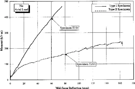
Mirmiran (Mirmiran et al. 2000) tested sixteen specimens with 2.75m long were fabricated from two different tubes (spin-cast or filament-wound). The spin-cast tubes were over-reinforced while the filament-wound were under-over-reinforced. The samples were loaded axially, and then lateral loads were applied while keeping the axial load constant. The flexural capacity of the spin-cast tubes was twice the filament-wound tubes as shown in Figure 2.3 where type I was the spin-cast CFFT and type II was filament-wound CFFT. The failure of spin-cast tubes was at compression due to the rupture of the tube. The failure of the filament-wound tubes happened due to fracture of the tube along its main winding
axis at low axial loads while compression governed at high axial loads. The observed slippage in the axially loaded columns can neglected. Lateral load capacity was seen to decrease as axial loads increased. Bilinear load-deflection behavior was observed, with the change coming at the cracking of concrete. The spin-cast tubes had lower deflections and higher capacities.
Figure 2.3: Moment–deflection curve for spin-cast and filament-wound CFFTS
(Mirmiran et al. 2000).
Fam (Fam et al. 2005) tested three beams and five short columns full-scale rectangular concrete-filled rectangular filament-wound glass fiber reinforced polymer (GFRP) tubes to study the flexural behavior of CFFTs and to obtain their axial load–bending moment interaction diagram. The tubes were manufactured in two different sizes 271 x 164 and 374 x 266 mm as shown in Figure 2.4(a). The stacking sequence for the flanges was [90, 45, -45, -45, --45, 0, 0, 90, 0, 0, -45, --45, -45, --45, and 90], while that of the webs was [90, -45, --45, 45, -45, 90, 45, -45, 45, -45, 90] as shown in Figure 2.4(b). The inner tube surfaces were coated with epoxy resin then coarse silica sand was applied to produce a rough texture as shown in Figure 2.4(c). Figure 2.5 show the tested beams cross sections “a”, “b” and “c” denote totally and partially filled large tube and totally filled small tube respectively. Five short columns consisted of the small GFRP tubes with 680 mm long were filled with concrete. All columns were tested under concentric or eccentric axial compression loads applied at various eccentricities. Columns C1, C3, C4, and C5 were tested using a setup
with free rotation allowed at both ends. Specimen C2 was tested between two fixed platens, without allowing end rotation. All samples details shown in Figure 2.6. Significant nonlinearity observed for Laminates with fibers orientation angle ±45 degrees under tension and compression as shown in Figure 2.7. The capacity of the beam with inner void was smaller than the totally filled tube by 22% but it had 56 % lighter in weight. Totally filled tube failed in tension by rupture of FRP. The partially filled tube failed in compression due to the buckling and fracture of the concrete compressive flange as shown in Figure 2.10. The depth of compression zone in CFFT beams after cracking was ranged from 20 to 30% of the section depth and linear strain distribution was observed as shown in Figure 2.8. Increasing the reinforcement ratio by 55%, it leads to increase in the flexural strength by 41%. The confinement effect in CFFTs columns was reduced due to bend of the flat sides of the FRP tube bend outwards then the concrete core loose restraint. All columns failed in brittle manner by fracture of the FRP tube at the round corner. Figure 2.9 show the effect of eccentricity in the axial capacity of CFFTs.
Figure 2.4: Details of GFRP tubes tested by (Fam et al. 2005).
Figure 2.5: Casting setup of CFFT beams tested by (Fam et al. 2005).
Figure 2.7: Load-deflection behavior of tested beams by (Fam et al. 2005).
Figure 2.9: Load-axial strain behavior of tested columns by (Fam et al. 2005).
Mohamed (Mohamed and Masmoudi 2010c) tested ten circular CFFTs under four-point bending load with 213 mm diameter and 2000 mm length. The studied parameters were the FRP tube thickness, concrete compressive strength, type of internal reinforcement (steel or FRP bars), and type of transverse reinforcement (spiral steel or FRP tube). The results showed that the reinforced concrete filled GFRP tubes (RCFFT) had higher strength, ductility, stiffness, and cracking load than the beam reinforced with a spiral steel. The deflection for RCFFTs was lower than the deflection for the beam reinforced with a spiral steel. Insignificant effect observed between using 30 and 45 MPa concrete compressive strength. The axial stiffness of the FRP tubes had significant effect in the strength, ductility, and deflection of RCFFTs. An acceptable theoretical analysis was presented to predict the ultimate and yield moment capacities of FRP or steel–RCFFT beams.
2.3.
Bond in Concrete Filled FRP Tubes
Bond development is one of the first fundamental requirements for any concrete structure, loads transfer from concrete to the reinforcement by bond. Therefore, the bond quality has a notable effectiveness on crack formation according to that it will also effects on the spacing between cracks and crack width.
The FRP tube in the case of concentrically loaded column provides hoop confinement, and therefore, the mechanical bond between FRP and concrete is not important. For flexural loads, the FRP tube plays a significant role. It confines the concrete in the compression zone and acts as the flexural and shear reinforcement at the same time. This requires development of the full composite action between FRP tube and concrete. Therefore, a mechanical bond is necessary (Samaan 1997). There are many ways to enhance the mechanical bond between the FRP tube and concrete like sand coating, resin ribs, shear connector, and internal crossing bars.
When flexural tests on CFFTs (without internal reinforcement) are carried out, excessive slip may occur between the concrete core and the FRP tube. This slip may adversely affect the composite action of the system unless special measures are taken, such as roughening the inner surface of the tube (Fam and Rizkalla 2002). If internal rebar reinforcement is
used and no bond enhancing is done, slip measured at both ends may be very small and can be neglected (Cole and Fam 2006).
Mirmiran (Mirmiran et al. 1998a) used interior shear ribs to enhance the mechanical bond between square FRP tube and concrete as shown in Figure 2.11. The results showed the presence of shear ribs could arrest any separation or slippage. The shear ribs allowed full utilization of the tube. The shear ribs provided high efficiency in transferring the load between the tube and the concrete core.
Figure 2.11: Interior shear ribs of the FRP tubes (Mirmiran et al. 1998a).
Mirmiran (Mirmiran et al. 1998a) tested thirty-five CFFT columns to study the effect of using adhesive bond and the mechanical bond between square FRP tubes and concrete in square CFFT columns. Three CFFTs were made using special collapsible mandrel with interior shear ribs. Thirty-two CFFT with and without interface bond were tested, two methods used to fabricate the FRP jacket (multi-layered and single-warp) for adhesive bonded samples. Polyester resin was used to adhesive the FRP layers to the concrete columns after 28-day form concrete casting in the adhesive bonded samples. The authors reported that the adhesive bond did not affect the capacity of the columns. The mechanical
bond (shear ribs) improved the performance of the section by distributing the confinement more efficient around the tube perimeter.
Ahmad (Ahmad 2004) tested CFFTs as deep beam and short beam under flexure and fatigue. He concluded that slippage is probably the single most important factor that dominates the fatigue behavior and fatigue life of CFFT beams. Fatigue life is directly related to the amount of slippage that occurs between the concrete core and the FRP tube. Slippage reduces the composite action in fatigue loading at a much greater rate when compared with static and quasi-static response.
Nelson (Nelson et al. 2008a) tested six push-through CFFT specimens embedded into concrete footings under axial compression load as shown in Figure 2.12. The aim of their tests was determining the interfacial shear strength (bond) between the GFRP tube and concrete.
Based on the experimental results for this type of tubes the average ultimate bond strength between the GFRP tube and the concrete is 0.75 MPa this value can be changed according to the surface texture, preparation of the FRP tube, concrete rupture modulus, and confining steel reinforcement in the footing. Once the bond reached the ultimate strength, it dropped to a level of about 50 to 60 percent of the ultimate bond strength as shown in Figure 2.13.
Figure 2.13: Bond stress – slip behavior of push-through specimens (Nelson et al.
2008a).
Ji (Ji et al. 2009) investigated the effect of the thickness of the FRP ribs and FRP skin on the interfacial bond strength. Five groups of specimens tested under push-out test. The specimens Group “A” and “B” were a normal FRP tube filled with concrete with variation on the thickness of the tube wall. Groups “C”, “D”, and “E” were a FRP tubes with FRP ribs with variation on the ribs thickness as shown in Figure 2.14. The results were opposite to the common belief, the interfacial shear strength decreases as the rib thickness increases. The authors reasoned that to the lower of concrete strength used. The Results also showed that the increasing the tube skin thickness increases the interfacial bond in the normal FRP tubes.
Belzer (Belzer et al. 2013) investigated the degree of composite action between rectangular pultruded GFRP tube and concrete. The objective of this research was done by testing twelve beam specimens under four-point flexural loads. The specimens were classified to four different configurations, three beams for each configuration type. The first configuration was an empty GFRP tube (A); the second configuration was concrete filled GFRP tube (B); the third configuration was concrete filled GFRP tube with epoxy bonding of the flanges (C); the fourth configuration was concrete filled GFRP tube with epoxy bonding all interior surface (D) as shown in Figure 2.15. All specimens had the same dimensions 3.5 m long with 3.05 m clear span, 152 mm width and 203 mm depth. The tube flange thickness was 9.5 mm and the web thickness was 6.4 mm.
Figure 2.15: Beam configurations (Belzer et al. 2013).
The results indicated that using epoxy to bond the FRP tube to concrete increases the flexural capacity and stiffness significantly. The load-deflection curves for the four beams are shown in Figure 2.16. The curves show the significant effect of bond between the FRP tube and concrete on the flexural capacity and stiffness of rectangular CFFTs. Based on the results of strength, stiffness, slippage between the FRP tube and concrete and the neutral axis location, the authors reported that the fully bonded and partially bonded achieve acceptable composite action performance more than the other beam configurations. An analytical model was developed to predict the behavior of the fully bonded composite CFFTs (D). The model results agreed well with the experimental results for the fully bonded beam (D).
Figure 2.16: Load deflection curves for beams (Belzer et al. 2013).
2.4.
Concrete Filled FRP Tubes (CFFTs) Connections
The CFFT connections are classified to two types, joints between members and splices in the same member. The previous research about CFFTs connections is very limited. Lai (Lai 2010)studied connections between CFFT columns and footings. Four types of connections were studied by Zhu (Zhu 2004) splices, beam to column connections, column to RC pier caps, and column to RC footings. Zakaib (Zakaib and Fam 2012) studied a moment CFFT connection.
Zhu (Zhu 2004) studied an innovative modular bridge pier system using stay-in-place FRP forms filled with concrete as shown in Figure 2.17. Four different CFFT connections were investigated in this study. A Male-Female connection without dowel bars was used to connect one CFFT to the pier caps, while dowel bars without embedment was used to connect it to the RC footing (Frame 1). The second column was connected to the pier cap by male-female connection with dowel bars, and dowel bars with embedment into the RC footing was used to connect it to the footing (Frame 2). The pile cap was a stay-in-place form also made of FRP sheets and attached with an extra sheet on top for negative moment continuity. A bonding agent was used in all connections also the gap between the tube and the RC footing were filled with a cement grout mixed with the same bonding agent. It was observed that the male-female joints lacked the structural integrity necessary for this
application. (Frame 1) had higher initial stiffness despite the absence of dowel bars and embedment. Embedding the CFFT into the RC footing produced a beneficial effect for the connection. The study also showed that the internal reinforcement outside of the connection area is not necessary.
Zhu (Zhu 2004) also tested four columns to footing connections under cyclic load, three CFFT columns and a control RC column, all with similar RC footings. The three CFFT specimens included a cast-in-place CFFT column with starter bars from its RC footing, a precast CFFT column with starter bars from its RC footing and grouted ducts, and a precast CFFT column post-tensioned to its RC footing as shown in Figure 2.18. The reinforcement in all specimens was four 16 mm and four 19 mm diameter of Grade 414 MPa mild steel, expect for the post-tensioned CFFT column, which had eight 19.0 mm Grade B-7 high strength threaded rods with a yield strength of 724 MPa. The CFFT columns did not fail up to the displacement of 180 mm. Therefore, they were pushed monotonically to a displacement of 300 mm, equivalent to a 13.3% drift ratio. The loading rate for the monotonic loading phase was kept the same as that for µ of six, which was 36.6 mm/min. Separation between the FRP tube and footing was observed at high displacements, but the load was still transferred effectively as sown in Figure 2.19. All three joint methods performed in a very similar manner and were much more ductile than the control RC column as shown in Figure 2.20. The development in the performance was a result due to the confinement of the concrete core by the tube.
Figure 2.17: CFFTs connections studied by (Zhu 2004).
Figure 2.18: CFFT Column- footing connections studied by (Zhu 2004)(a): for precast CFFT, (b): for post-tensioned CFFT, (c): for Cast-in-Place Columns.
Figure 2.19: Separation between FRP Tube and RC Footing (Zhu 2004).
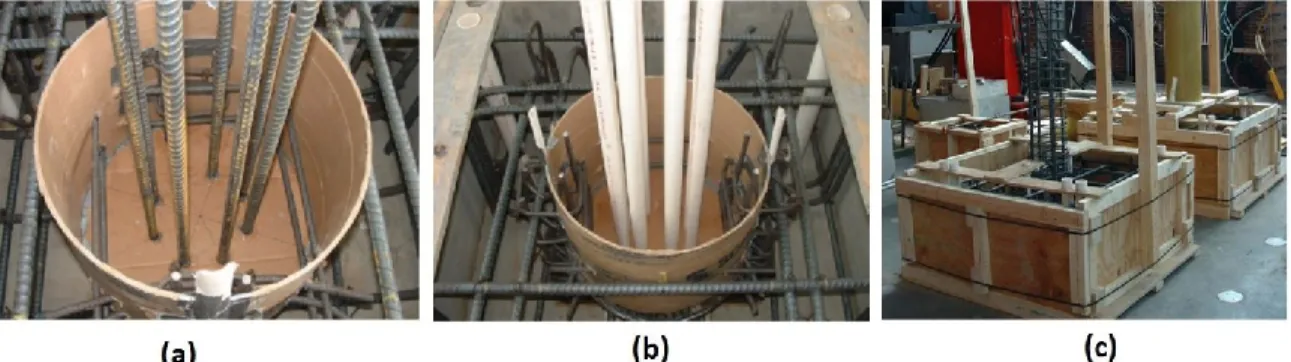
Zhu (2004a) also investigated four techniques for CFFTs splices, grouted steel bars, grouted FRP bars, un-bonded post tensioning bars and FRP sockets as shown in Figure 2.21. A control un-spliced CFFT section was also prepared for comparison. The five specimens were tested under a four-point bending test. The post tensioning beam recorded higher strength than the other spliced beams but less than the un-spliced beam by 30 %. The Failure of the two bar-spliced beams was similar, failure was determined based on excessive bar slippage and joint opening, but with more sharp load drops. Figure 2.22 shows the load-deflection curves for the tested CFFT beams.
Figure 2.21: Specimen Casting and assembly: (a) PVC Pipes Being Pulled Out
After Partial Setting of Concrete, (b) Enlarged Ducts Made by PVC Pipes, (c) Consolidating Grout in Steel Bar Spliced CFFT Beam, (d) Post-Tensioning Procedure, (e) Applying Epoxy to Inside Surface of FRP Socket Spliced Beam, (f) Close-up View of
Figure 2.22: Comparison of load-deflection responses of CFFT beams (Zhu 2004)
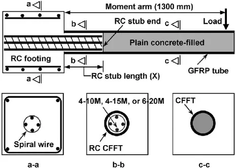
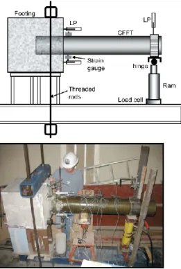
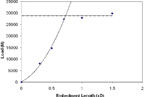
Lai (Lai 2010) tested two types of moment connections between an unreinforced CFFT and a reinforced concrete footing. The first type was direct embedment of the precast CFFT into the footing as shown in Figure 2.23. The second type was the tube was adhesively bonded to a steel-reinforced concrete stub and was protruded from the top of the footing as shown in Figure 2.24. The aim of the research was determination of the minimum required embedded length and minimum required stub height to achieve the strength of the CFFT members. Five cantilever samples were tested with the first type of connection as shown if Figure 2.25. The Results showed that the optimal embedment length of the CFFT into RC footing is 0.73 times the diameter of the CFFT. Pseudo-ductility was observed in flexure for the CFFT embedded into the RC footings with at least the optimal length. Radial cracks in the footings were observed in all specimens. These cracks were fine in the specimens with embedment lengths equal to or greater than the optimal length as shown in Figure 2.26. Figure 2.27 shows the effect of embedment length into footing on ultimate load capacity of CFFT. In the second type of connections, eight cantilever specimens were tested. A short reinforced concrete stub was cast as part of the footing. Four samples tested with varying stub lengths, two with different steel reinforcement ratios in the stub, and two were tested in low-cycle fatigue. The Results showed that the optimal RC stub height is about 1.1 times the diameter of the CFFT and the minimum longitudinal steel
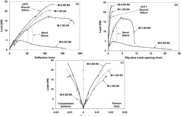
reinforcement ratio of 3.4% was required in the RC stub to achieve the flexural strength of the CFFT. Figure 2.28 shows the failure of the CFFT beams which, depending on the RC stub height. The responses of specimens with different RC stub lengths with load-deflection; load-slip plus crack opening; and load-longitudinal strain at stub end were showed in Figure 2.29.
Figure 2.23: First connection type: direct embedment of the precast CFFT into the
footing (Nelson et al. 2008a).
Figure 2.24: Second connection type: direct embedment of the precast CFFT into