HAL Id: hal-02119950
https://hal.archives-ouvertes.fr/hal-02119950
Submitted on 1 Jul 2019
HAL is a multi-disciplinary open access
archive for the deposit and dissemination of sci-entific research documents, whether they are pub-lished or not. The documents may come from teaching and research institutions in France or abroad, or from public or private research centers.
L’archive ouverte pluridisciplinaire HAL, est destinée au dépôt et à la diffusion de documents scientifiques de niveau recherche, publiés ou non, émanant des établissements d’enseignement et de recherche français ou étrangers, des laboratoires publics ou privés.
Helical Roller Burnishing Through Finite Element
Simulations and Experiments
Landry Kamgaing Souop, Alain Daidié, Yann Landon, Johanna Senatore,
Mathieu Ritou
To cite this version:
Landry Kamgaing Souop, Alain Daidié, Yann Landon, Johanna Senatore, Mathieu Ritou. Inves-tigation of Aluminum Alloy Properties During Helical Roller Burnishing Through Finite Element Simulations and Experiments. International Joint Conference on Mechanics, Design Engineering & Advanced Manufacturing, Jun 2018, Carthagena, Spain. pp.440-450, �10.1007/978-3-030-12346-8_43�. �hal-02119950�
helical roller burnishing through finite element
simulations and experiments
L. Kamgaing Souop1, A. Daidie1, Y. Landon1, J. Senatore1, and M. Ritou2
1 ICA (Institut Clément Ader), Université de Toulouse, UPS, INSA,
ISAE-SUPAERO, MINES-ALBI, CNRS, 3 rue Caroline Aigle, 31400 Toulouse, France
landry-arnaud.kamgaing-souop@univ-tlse3.fr alain.daidie@insa-toulouse.fr
yann.landon@univ-tlse3.fr johanna.senatore@univ-tlse3.fr
2 LS2N (Laboratoire des Sciences du Numérique de Nantes, UMR CNRS 6004),
Université de Nantes, 2 avenue du Pr Rouxel, 44475 Carquefou, France
mathieu.ritou@univ-nantes.fr
Abstract
Industry is always looking for ways to increase the lifetime of assemblies, especially the fatigue lifetime, from the production phase of fastening holes onwards. Helical roller burnishing is presented here as an innovative mechanical surface treatment. Applied directly after orbital drilling, this technique induces superficial plastic strains that reduce surface roughness and increase hardening and compressive residual stresses. Several studies on 3D finite element models of burnishing have been carried out but they are very time-consuming. In this review, a comparative numerical study of helical burnishing (in terms of calculation time and results on residual stress) be-tween one 3D and two 2D plane strain finite element simulations is performed on 2024-T351 aluminum alloy drilled parts. The impact of the process operating parame-ters is also investigated. This comparison shows fairly similar results regarding the re-sidual stress profiles but levels are rather different. This could be explained by the kinematics of complex helical roller burnishing, which is strongly three-dimensional. The numerical results of one of the cases studied reveal compressive residual stresses of around -100 MPa and -490 MPa in the radial and circumferential directions of the hole, respectively. Burnishing depth and spindle rotation speed have a great impact on the final residual stress profiles. These simulations are then confronted with experi-mental results obtained during tests carried out using an orbital drilling unit (ORBIBOT). This demonstrates the interest of the modeling implemented and also points out ways to improve the models developed.
Keywords: Helical roller burnishing; Residual stresses; Hardening; Finite element
1 Introduction
Orbital drilling (or helical milling) is a hole-making process in which a milling tool moves along a helical path while spinning on its axis (Figure 1a). It has become in-creasingly popular in hole drilling processes, particularly in the aerospace industry. Compared to conventional drilling, orbital drilling has proved to be particularly ad-vantageous to achieve aeronautical-quality drilling through complex assemblies of metallic materials in a single operation [1] [2] [3]. However, this process needs to be improved, mainly in terms of the mechanical properties of the drilled parts. In fact, the enhancement of fatigue lifetime is constantly requested for drilled parts. This is generally achieved by the production of compressive residual stresses and hardening in the surface layers of parts. Several authors [4] [5] [6] [7] [8] have shown that bur-nishing introduces compressive residual stresses, and improves the roughness and the hardening of parts. Delgado et al. also noted that roller burnishing gives a better state of residual stresses and hardening compared to shot peening and laser shock peening [9]. Hassan and Al-Bsharat have shown that burnishing increases the fatigue life of aluminum pieces [10]. As a novel mechanical surface treatment, helical roller bur-nishing (or orbital roller burbur-nishing) appears to be an excellent solution to the lifetime problem insofar as it can be applied immediately after orbital drilling. The main spec-ificity of this innovative roller burnishing technique lies in the kinematics of the tool. As an orbital drilling tool, the burnisher (which is shaped like a torus) rotates around its own axis and simultaneously describes a helical path around the hole axis (Figure 1b). But the benefits of helical burnishing need to be investigated in depth. A 3D fi-nite element simulation of conventional roller burnishing has been carried out by Bal-land et al. and the results (in terms of geometric state of the surface and residual stresses), obtained in a reasonable simulation time, demonstrate the possibility of us-ing this type of modelus-ing as an efficient replacement for 2D plane strain finite ele-ment simulation, which is rather limited and approximate [5]. Nevertheless, the simu-lation time is still considered as huge and the results are in only qualitative agreement. Thus, in this review, a comparative numerical study (in terms of calculation time and results on residual stress) between one 3D and two 2D plane strain finite element simulations is performed first of all. The impact of operating parameters (burnishing depth, spindle rotation speed) is then studied. These simulations are finally confronted with experimental results. All these studies were performed on 2024-T351 aluminum alloy drilled parts using the finite element software ABAQUS®.
Fig. 1. Schematic drawing of orbital drilling (a) and helical roller burnishing process (b)
2 Finite element modeling of helical roller burnishing process
2.1 Geometry, material characterization and modeling
As mentioned earlier, we first simulated a 3D model on the one hand and two 2D models (which are very time cost effective) on the other. It is important to start by precisely defining the different interactions that occur in the planes involved.
Figure 2-a represents the directions of the different forces on a half hole during orbital burnishing. Figures 2-b and 2-c show the decomposition of orbital burnishing kine-matics and forces in the 2 planes where 2D models were run. The purpose here is to compare the results obtained by the 2D and 3D models and to assess whether they are reliable. The 3D model was used to give the radial, orthoradial and axial residual stresses (R, , Z) while the first 2D model gave radial and orthoradial residual
stresses (R, ) and the second 2D model gave axial residual stresses (Z).
Fig. 2. Decomposition of orbital burnishing kinematics
In order to further reduce computation time, all these simulations were run on a por-tion of the hole (one eighth). Mathurin has shown that this porpor-tion achieves a good compromise between the process studied and the calculation time [15]. The length of
the specimen considered was 25.4 mm. It was chosen large enough to minimize edge effects. Its thickness was 1 mm. The hole diameter was 6.35 mm and the radius of the helical path was 0.8 mm. In order to study the impact of the burnishing depth, the dif-ferent tool diameter values were 4.762 mm, 4.79 mm, 4.81 mm and 4.83 mm, which gave burnishing depths “e” of 6 µm, 20 µm, 30 µm and 40 µm respectively. The tool height was 0.6 mm.
(1)
A: Yield stress B: Strain factor C: strain rate factor n: strain exponent
Tf: Melting temperature
T0: Ambient temperature
m: temperature exponent
This study was performed on AA2024-T351 aluminum alloy parts. It was fundamen-tal to determine a robust material for the constitutive model so that the strains could be modelled accurately. The constitutive model used for this material is generally a Johnson-Cook model as defined by [1] [11] [12].
However, the parameters of this constitutive model depend on the type of simula-tion and the experimental operating condisimula-tions used to assess them. As we were using severe plastic deformation and high strain rate process modeling, the following pa-rameters were considered.
Table 1. Material constants for the Johnson-Cook strain rate dependent yield stress [11]
A (MPa) B(MPa) C n (s-1
) Tf (K)
265 426 0.015 0.34 103 775
The tool was made of a tungsten carbide material, which had much greater hard-ness than our specimen (HVWC=2242 and HVAA2024-T351=137). It could, therefore, be
represented as a rigid body, which brought two main benefits. Firstly, rigid body modelling allowed the tool to be controlled by a single reference point. Then, strains of the tool were not assessed during analysis. All this helped to reduce calculation time drastically.
Like the constitutive model, contact between parts is another very critical criterion in numerical studies. This parameter governs the modeling of the surface interactions of helical burnishing. The contact model usually used is a Coulomb model [5] [13] [14]. Like Balland et al. [5], we used a master-slave contact algorithm where the fric-tion was taken into account using a penalty method and a value of 0.2.
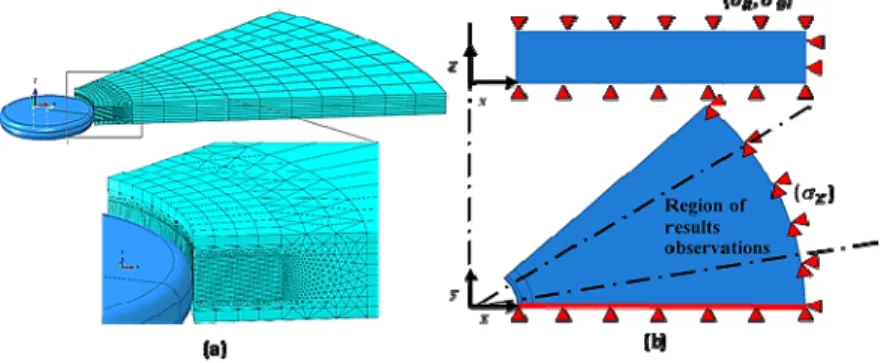
2.2 Meshing and boundary conditions
In order to obtain a suitable balance between results and calculation time, our models were meshed with different types of elements. In fact, it is important to have a very fine mesh near the domain of contact between parts. Thus, C3D8R elements of 0.02 mm dimensions were used in this area. The domain near the specimen edges was meshed with C3D8R elements of 0.12 x 1.705 x 1.75 mm3. The intermediate domain
was meshed with C3D4 elements to ensure the link between them (Figure 3-a). The specimens in the two 2D models were meshed with CPE4R elements. As the tool was modelled as rigid, there was no need to mesh it.
The part was embedded on the external edge. This condition allowed material flow along the z-axis. Symmetric conditions along the radial axis were applied on the edge where the tool and the part intersected each other at the beginning; the other edge was free. These boundary conditions were established in accordance with Mathurin’s find-ings [15]. He showed that these conditions, although too restrictive, are more realistic than free edge conditions. However, these conditions impose the determination of a region where the results will be observed. Symmetric conditions along the axial axis were also applied on the top and bottom edges of the part. Figure 3-b shows all these boundary conditions.
On the tool, we applied the following boundary conditions: - V3 = 40 mm/min (Axial feed Vfa)
- Norb = 1000 rpm (Orbital velocity)
- VR3 = 40000 rpm and VR3 = 0 rpm (Spindle velocity N). Two velocity val-ues were selected to study the impact on the results.
In order to reduce calculation time still further, we just simulated 3 passages of the tools at the surface middle plane.
Fig. 3. Helical milling: mesh (a) and boundary conditions (b)
3 Experimental procedure
Fig. 4. ORBIBOT orbital drilling unit and specimen
The experimental study was done with a CNC machine (DMG DMU85eVo) equipped with an ORBIBOT orbital drilling unit (Figure 4). Before helical burnishing was exe-cuted on the aluminum alloy specimens, they were previously drilled with a 6.35 mm
diameter hole. The burnishing depth was 10 µm and the operating conditions were Vfa
= 40 mm/min, N = 40000 rpm, Norb = 1000 rpm. The orbital rotation was clockwise and the process was conducted without lubrication. The CNC machine was also equipped with a Kistler 9257B measurement system (which measures helical burnish-ing forces). The software used for data acquisition and processburnish-ing was WITIS.
4 Results and discussion
Simulations were run on a computer having 32 GB RAM and an Intel® Xeon® CPU of 1.70 GHz (2 processors). The mean values of simulation calculation time are shown in the table below:
Table 2. Time calculation for the different models
Model 3D 2D plane strain_1 2D plane strain_2
Calculation time 4 days 10 hrs 13 min 46 min 17 sec 2 hrs 07 min 18 sec
It can be seen that the three-dimensional models need several days while the two-dimensional ones only need a few hours. This could be very helpful regarding the study of different operating conditions (burnishing depth, spindle and orbital veloci-ties, axial feed, etc.).
4.1 Comparison between 2D and 3D models
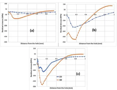
Figure 5 compares residual stresses obtained with our different models for a burnish-ing depth e = 40 µm and a spindle velocity N = 40000 rpm.
Fig. 5. Comparison of radial (a), orthoradial (b) and axial (c) residual stresses between 3D and 2D
models for e = 40 µm and N = 40000 rpm
Despite the fact that the stress levels obtained with 3D and 2D models are quite different, the stress state profiles around the hole are nevertheless quite comparable. The differences in stress levels could be explained by the complex kinematics of the tool during orbital burnishing. The hypotheses of plane strains (especially the plane stress hypothesis in the first 2D model) cannot be used despite the fact that the dimen-sions of the parts are large. In fact, the axial component of the kinematics might not be negligible in comparison with the radial and orthoradial components. An axial speed decrease could reduce the axial force, thus bringing the predictions of these hy-potheses closer to observations. Further modeling in this direction should provide more information.
4.2 Impact of operating conditions
- Impact of burnishing depth
Figure. 6 shows the residual stresses obtained for different burnishing depths for a spindle velocity N = 40000 rpm.
Fig. 6. Impact of burnishing depth on radial (a), orthoradial (b) and axial (c) residual stresses
We observe that the levels of radial residual stresses increase with the burnishing depth. The conclusion seems to be the same for orthoradial and axial residual stresses. Moreover, the position of the compressive peak and the domain in compressive resid-ual state also increase with the burnishing depth. This can be explained by the high strain rates generated with the increase of the burnishing depth: the greater the depth, the greater the pressure and the greater the strains. But the last observation needs to be investigate more thoroughly by refining the meshing of the part. In fact, the curve ob-tained for e = 40 µm appears to be more accurate (more defined points) because this model mesh was less coarse over a certain distance from the hole.
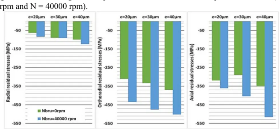
- Impact of spindle speed
Figure 7 shows the highest compressive residual stresses for 2 spindle velocities (N = 0 rpm and N = 40000 rpm).
The spindle velocity suppression leads to a smaller residual stress, especially in the orthoradial and axial directions. This could be explained by the greater friction of the tool when the spindle velocity is zero (The tool slips intensively on the borehole). This hypothesis could be confirmed by using a kinetic instead of a static friction law in future models.
It would have been preferable to compare all these numerical results with the experi-mental ones in terms of residual stresses. However, because the residual stress as-sessment relies on techniques that are rather difficult to set up, we firstly investigated this comparison in terms of global data (burnishing forces).
4.3 Burnishing forces
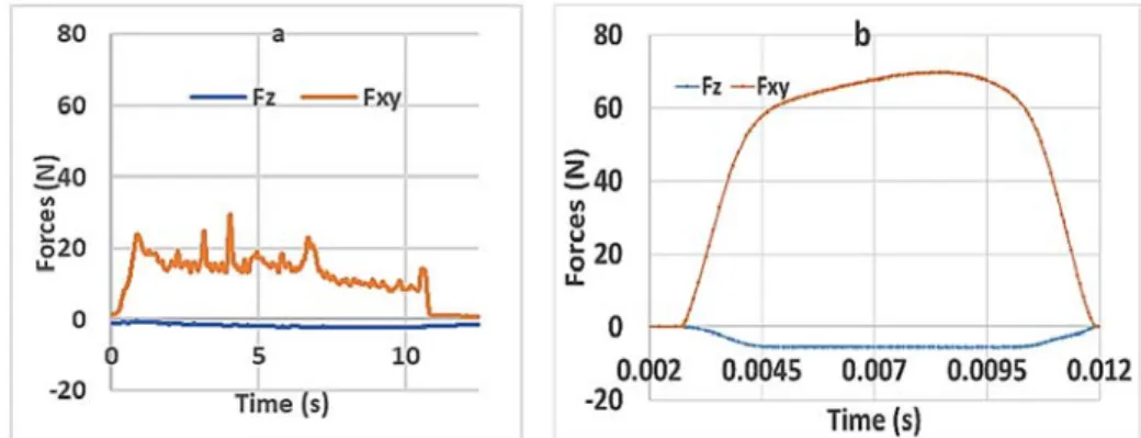
Figure. 8 shows the helical burnishing forces obtained numerically and experimental-ly (axial forces Fz and normalized transversal forces Fxy). Numerical forces are rep-resented only on one tool pass because simulations were not done on the total hole height and circumference.
Fig. 8. Helical burnishing forces: experimental (a) and numerical (b)
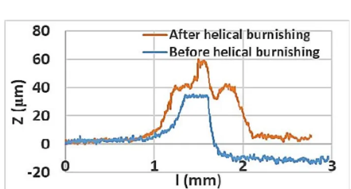
We noted a slight overestimation of numerical forces (70 N vs 25 N). In addition, a considerable amount of material was observed to adhere to the tool during experi-ments (Built Up Layer). Figure. 9 presents the burnisher outlines before and after hel-ical burnishing (height variation Z with position on the burnisher revolution axis l), obtained with an optical profilometer (Alicona InfiniteFocus SL). The Built-Up Layer indicates a large temperature increase and strong friction. This could explain the dif-ference in the levels of forces between experiments and modeling. It would be inter-esting to refine thermal effects and define a more suitable friction model in future models.
Nevertheless, the experimental residual stress measurements remain the best way to correlate all our numerical results. This operation is planned.
Fig. 9. Burnisher outlines before and after helical burnishing
5 Conclusion
We carried out a numerical study of the helical burnishing process on an AA2024-T351 aluminum alloy specimen. First of all, a comparison was made between two 2D plane strain models and a 3D model. This was done with a view to significantly re-ducing the calculation time of the simulations. The different geometries and assem-blies of our model were implemented in ABAQUS™ software, then a Johnson-Cook constitutive model and a rigid body were used to represent the part and the tool, re-spectively. The contact model defined between these two parts was a Coulomb model with friction penalty µ = 0.2. The results obtained showed that the 2D models were much more cost-effective than the 3D one (2 hours against 4 days). But the levels of residual stresses acquired with the 2D models were lower than those obtained with 3D despite the fact that outlines were comparable. An axial feed reduction might be help-ful in strong deformation strain hypotheses. In all cases, these results show that helical burnishing introduces compressive residual stresses into surface layers. We also noted that the operating conditions had a marked impact on the levels and depth of com-pressive residual stresses. The greater the burnishing depth was, the higher were the levels of compressive residual stresses and the greater were the depths they reached. However, numerical burnishing forces did not agree well with experiments: burnish-ing without lubrication exhibited thermal and tribological impacts which should be re-fined in modeling (material conductivity, specific heat, kinetic friction law). To obtain a more accurate contact model and thermal effects, tribological and temperature measurement experiments are planned. It will also be important to investigate the im-pact of other operating conditions (axial feed, direct or clockwise spindle rotation, etc.). Nevertheless, it is important to compare these numerical studies with experi-mental measurements of residual stresses obtained by helical burnishing, with a view to validating the models.
Acknowledgments
This work was carried out within the framework of the RODEO project, which re-ceived funding from the Clean Sky 2 Joint Undertaking under the European Union’s Horizon 2020 research and innovation program, grant agreement No 738219.
The authors are grateful to all the project participants for their support: PRECISE France, MITIS Engineering, KUKA Systems Aerospace France.
References
[1] R. Iyer, P. Koshy, and E. Ng, ‘Helical milling: An enabling technology for hard machining precision holes in AISI D2 tool steel’, Int. J. Mach. Tools Manuf., vol. 47, no. 2, pp. 205–210, Feb. 2007.
[2] D. Olvera, L. N. L. de Lacalle, G. Urbikain, A. Lamikiz, P. Rodal, and I. Zamakona, ‘Hole Making Using Ball Helical Milling on Titanium Alloys’, Mach. Sci. Technol., vol. 16, no. 2, pp. 173–188, Apr. 2012.
[3] G. He, H. Li, Y. Jiang, X. Qin, X. Zhang, and Y. Guan, ‘Helical milling of CFRP/Ti-6Al-4V stacks with varying machining parameters’, Trans. Tianjin Univ., vol. 21, no. 1, pp. 56–63, Jan. 2015.
[4] Y. C. Yen, P. Sartkulvanich, and T. Altan, ‘Finite Element Modeling of Roller Burnishing Process’, CIRP Ann., vol. 54, no. 1, pp. 237–240, Jan. 2005.
[5] P. Balland, L. Tabourot, F. Degre, and V. Moreau, ‘An investigation of the mechanics of roll-er burnishing through finite element simulation and exproll-eriments’, Int. J. Mach. Tools Manuf., vol. 65, pp. 29–36, Feb. 2013.
[6] L. Wagner, ‘Mechanical surface treatments on titanium, aluminum and magnesium alloys’,
Mater. Sci. Eng. A, vol. 263, no. 2, pp. 210–216, May 1999.
[7] A. A. García-Granada, G. Gomez-Gras, R. Jerez-Mesa, J. A. Travieso-Rodriguez, and G. Reyes, ‘Ball-burnishing effect on deep residual stress on AISI 1038 and AA2017-T4’, Mater.
Manuf. Process., vol. 32, no. 11, pp. 1279–1289, Aug. 2017.
[8] P. Balland, L. Tabourot, F. Degre, and V. Moreau, ‘Mechanics of the burnishing process’,
Precis. Eng., vol. 37, no. 1, pp. 129–134, Jan. 2013.
[9] P. Delgado, I. I. Cuesta, J. M. Alegre, and A. Díaz, ‘State of the art of Deep Rolling’, Precis.
Eng., vol. 46, pp. 1–10, Oct. 2016.
[10] A. M. Hassan and A. S. Al-Bsharat, ‘Improvements in some properties of non-ferrous metals by the application of the ball-burnishing process’, J. Mater. Process. Technol., vol. 59, no. 3, pp. 250–256, May 1996.
[11] G. R. Johnson and W. H. Cook, ‘A constitutive model and data for metals subjected to large strains, high strain rates and high temperatures’, Scribd, Apr-1983. [Online]. Available: https://www.scribd.com/document/81848138/A-Constitutive-Model-and-Data-for-Metals. [Accessed: 29-Jan-2018].
[12] ‘Verification of Johnson-cook Material Model Constants of Aa2024-t3 for Use in Finite Ele-ment Simulation of Friction Stir Welding and Its Utilization in Severe Plastic Deformation | Welding | Continuum Mechanics’, Scribd. Available: https://www.scribd.com/document/236104784/Verification-of-Johnson-cook-Material- Model-Constants-of-Aa2024-t3-for-Use-in-Finite-Element-Simulation-of-Friction-Stir-Welding-and-Its-Utilization-i. [Accessed: 29-Jan-2018].
[13] G. List, Etude des mécanismes d’endommagement des outils carbure WC-Co par la
caracté-risation de l’interface outil copeau : application à l’usinage à sec de l’alliage d’aluminium aéronautique AA2024 T351. Paris, ENSAM, 2004.
[14] M. R. S. John, A. W. Wilson, A. P. Bhardwaj, A. Abraham, and B. K. Vinayagam, ‘An inves-tigation of ball burnishing process on CNC lathe using finite element analysis’, Simul. Model.
Pract. Theory, vol. 62, pp. 88–101, Mar. 2016.
[15] F. Mathurin, Etude du processus de vissage par vis autoformeuse et élaboration d’une
mé-thode de dimensionnement adaptée. PhD thesis at University of Toulouse awarded by INSA,