ÉCOLE DE TECHNOLOGIE SUPÉRIEURE UNIVERSITÉ DU QUÉBEC
THESIS PRESENTED TO
ÉCOLE DE TECHNOLOGIE SUPÉRIEURE
IN PARTIAL FULLFILMENT OF THE REQUIREMENTS FOR THE DEGREE OF DOCTOR OF PHILOSOPHY
Ph.D.
BY
Andrei Vladimir POPOV
DESIGN OF AN ACTIVE CONTROLLER FOR DELAYING THE TRANSITION FROM LAMINAR FLOW TO TURBULENT FLOW OVER A MORPHING WING IN WIND
TUNNEL
MONTREAL, FEBRUARY 19 2010 © Copyright 2010 reserved by Andrei Vladimir Popov
BOARD OF EXAMINERS (THESIS PH.D.)
THIS THESIS HAS BEEN EVALUATED BY THE FOLLOWING BOARD OF EXAMINERS
Ms. Ruxandra Botez, Thesis Supervisor
Département de génie de la production automatisée à l’École de technologie supérieure
Mr. Patrick Terriault, President of the Board of Examiners
Département de génie mécanique a l’École de technologie supérieure
Mr. Stephane Halle, Member of the Board of Examiners
Department of mechanical engineering at École de technologie supérieure
Mr. Youmin Zhang, External Member of the Board of Examiners
Department of mechanical and industrial engineering at Concordia University
THIS THESIS WAS PRESENTED AND DEFENDED BEFORE A BOARD OF EXAMINERS AND PUBLIC
FEBRUARY 2, 2010
AKNOWLEDGMENTS
I would like to thank to my thesis supervisor, Dr. Ruxandra Botez, for the opportunity to work on this project and for her constant encouragement and support in finalizing this challenging work in the CRIAQ 7.1 project.
Thanks are also due to Dr. Teodor Lucian Grigorie for his collaboration in this work as well as to other students from LARCASE working together on this project: Mathieu Roux, Pierre Attal, Michel Labib, Julien Fays and Samuel Courchesne.
Many thanks are due to Dr. Patrick Terriault and Dr. Vladimir Brailovski as well as to their students from LAMSI, Daniel Coutu, Thomas George and Emeric Morellon, for their numerical and experimental collaboration in this project. I would also like to thank Dr. Mahmoud Mamou and Dr. Youssef Mebarki from the NRC-IAR (The National Research Council of Canada Institute for Aerospace Research) for their collaboration in infrared testing, and to Dr. Octavian Trifu from Ecole Polytechnique for his advice in aerodynamics.
We would like to thank to George Henri Simon for initiating the CRIAQ 7.1 project, as well as Philippe Molaret from Thales Avionics and Eric Laurendeau from Bombardier Aeronautics, for their collaboration in this work.
Thanks to Bombardier Aerospace, Thales Avionics, the NRC-IAR (National Research Council Institute for Aeronautical Research), the CRIAQ (Consortium for Research and Innovation in Aerospace in Quebec) and the NSERC (National Sciences and Engineering Research Council) for the funding of the global CRIAQ 7.1 project.
CONCEPTION D’UN CONTRÔLEUR ACTIF POUR LE RETARD DE LA TRANSITION DE L’ÉCOULEMENT LAMINAIRE AU TURBULENT SUR UNE
AILE À GEOMÉTRIE DU PROFIL VARIABLE DANS LE TUNNEL À VENT
Andrei Vladimir POPOV RÉSUMÉ
L’industrie aérospatiale est motivée par la réduction de la consommation de combustible pour les avions de transport à longue croisière, principalement par la réduction de la trainée. L’objectif principal de ce projet est de concevoir un système de contrôle actif pour la géométrie du profil d’aile d’une aile d’avion pour permettre la réduction de la trainée. La réduction de la trainée peut être obtenue par la modification du point de transition entre l’écoulement laminaire et écoulement turbulent, qui doit être positionnée le plus proche possible du bord de fuite du profil de l’aile. La position du point de transition à un rôle très important dans ce projet, et en conséquence ce travail se concentre sur le contrôle de la position du point de transition sur le profil de l’aile, comme effet du contrôle de la déflection de la peau flexible installée sur l’extrados de l’aile.
Ce travail présente la modélisation, la réalisation, l’instrumentation et les essais expérimentaux d’une aile avec géométrie variable du profil du début de la conception jusqu’aux essais sur le banc et dans la soufflerie. Plusieurs essais en soufflerie pour plusieurs valeurs de nombre Mach et angles d’incidence ont été réalisés dans le tunnel de 2 m × 3 m appartenant à l’Institut de Recherche Aerospatiale - Conseil National de Recherche du Canada. Une aile rectangulaire avec une envergure finie et un profil d’aile variable due à une peau flexible installée sur l’extrados du profil a été instrumenté avec des capteurs Kulite. Le nombre de Mach a été varié de 0.2 jusqu'au 0.3 et avec l’angle d’incidence de -1o jusqu’au2o. Les signaux de pression ont été mesurés, analysés et comparés par la valeur moyenne du coefficient de pression et la déviation standard avec les valeurs obtenues par le code CFD XFoil. Les valeurs mesurées ont été analysées par un logiciel maison conçu à l’aide de Matlab/Simulink pour détecter la magnitude du bruit dans la couche limite de l’écoulement et localiser la position du point de transition sur l’extrados de l’aile. Cette analyse a été nécessaire pour détecter les ondes Tollmien-Schlichting, apparaissant suite à la transition entre l’écoulement laminaire et turbulent.
La peau flexible changeait sa forme grâce à deux actionneurs pour réaliser la forme du profil optimisé correspondante à chaque condition du l’écoulement de l’air dans soufflerie. Les deux actionneurs en alliages à mémoire de forme, ayant un comportement non-linéaire, ont été contrôlés par un contrôleur avec plusieurs méthodes de contrôle. Cette méthodologie présentée dans ce travail et les résultats obtenus montrent la validité du concept en temps réel dans les conditions expérimentales.
DESIGN OF AN ACTIVE CONTROLLER FOR DELAYING THE TRANSITION FROM LAMINAR FLOW TO TURBULENT FLOW OVER A MORPHING WING
IN WIND TUNNEL
Andrei Vladimir POPOV ABSTRACT
The aerospace industry is motivated to reduce fuel consumption in large transport aircraft, mainly through drag reduction. The main objective of the global project is the development of an active control system of wing airfoil geometry during flight in order to allow drag reduction. Drag reduction on a wing can be achieved through modifications in the laminar-to-turbulent flow transition point position, which should be situated as close as possible to the trailing edge of the airfoil wing. As the transition point plays a crucial part in this project, this work focuses on the control of its position on the airfoil, as an effect of controlling the deflection of a morphing wing airfoil equipped with a flexible skin.
The paper presents the modeling and the experimental testing of the aerodynamic performance of a morphing wing, starting from the design concept phase all the way to the bench and wind tunnel tests phases. Several wind tunnel test runs for various Mach numbers and angles of attack were performed in the 6 × 9 ft2 wind tunnel at the Institute for Aerospace Research at the National Research Council Canada. A rectangular finite aspect ratio wing, having a morphing airfoil cross-section due to a flexible skin installed on the upper surface of the wing, was instrumented with Kulite transducers. The Mach number varied from 0.2 to 0.3 and the angle of attack between -1o and 2o. Unsteady pressure signals were recorded and analyzed and a thorough comparison, in terms of mean pressure coefficients and their standard deviations, was performed against theoretical predictions, using the XFoil computational fluid dynamics code.
The acquired pressure data was analyzed through custom-made software created with Matlab/Simulink in order to detect the noise magnitude in the surface airflow and to localize the transition point position on the wing upper surface. This signal processing was necessary in order to detect the Tollmien-Schlichting waves responsible for triggering the transition from laminar to turbulent flow.
The flexible skin needed to morph its shape through two actuation points in order to obtain an optimized airfoil shape for several flow conditions in the wind tunnel. The two shape memory alloy actuators, having a non-linear behavior, drove the displacement of the two control points of the flexible skin towards the optimized airfoil shape. This thesis presents the methodology used and the results obtained from designing the controller of the two shape memory actuators as well as the methods used for morphing wing control in the wind tunnel tests designed to prove the concept and validity of the system in real time.
TABLE OF CONTENTS
Page
INTRODUCTION ...1
CHAPTER 1 STATE OF THE ART ...6
1.1 Aerodynamic methods for laminar flow improvement ...6
1.2 Morphing wings equipped only with actuators ...8
1.3 Materials and actuators: use in the morphing wing design ...10
1.4 Integrated morphing wing studies ...12
1.5 Integrated morphing aircraft studies ...13
CHAPTER 2 OBJECTIVES AND ORIGINALITY ...23
2.1 The morphing wing model concept and its function ...23
CHAPTER 3 THEORY DEVELOPPED ...29
3.1 Modeling the wind tunnel parameters and pressure and forces acting on the morphing wing airfoil estimation ...29
3.1.1 Validation of the XFoil CFD code by use of experimental data from wind tunnel tests on the original airfoil WTEA ...22
3.1.2 Aerodynamic analysis of the modified airfoils by use of XFoil ...33
3.1.3 Computation of the aerodynamic characteristics in wind tunnel and estimation of the forces acting on the flexible skin during tests ...37
3.2 Modeling the dynamic pressure signal and transition position measured by use of optical sensors ...41
3.2.1 Modeling the turbulent flow by Gaussian distribution ...41
3.2.2 Equivalences between noise level and velocity RMS in the wind tunnel ...43
3.2.3 Modeling and simulation of the optical sensors measurements ...48
3.3 Shape memory alloys (SMA) actuators modeling and control function design ...53
3.4 Controller simulation in closed loop using airflow pressure distribution ...61
CHAPTER 4 ARTICLE 1: TRANSITION POINT DETECTION FROM THE SURFACE PRESSURE DISTRIBUTION FOR CONTROLLER DESIGN ...71
4.1 Introduction ...73
4.2 Experimental setup ...75
4.3 Theoretical considerations ...76
4.4 Results obtained for a NACA 4415 airfoil ...82
4.5 Results obtained for the WTEA-TE1 airfoil ...85
CHAPTER 5 ARTICLE 2: CLOSED-LOOP CONTROL SIMULATIONS ON A
MORPHING WING ...93
5.1 Introduction ...96
5.2 Closed-loop controller design ...102
5.3 Results and discussion ...114
5.4 Conclusions ...120
CHAPTER 6 ARTICLE 3: VARIATIONS IN OPTICAL SENSOR PRESSURE MEASUREMENTS DUE TO TEMPERATURE IN WIND-TUNNEL TESTING ...124
6.1 Introduction ...126
6.2 Experimental setup description ...127
6.3 Wind-tunnel data post-processing details ...129
6.4 Results analysis ...134
6.5 Transition detection ...136
6.6 Conclusions ...140
CHAPTER 7 ARTICLE 4: DRAG REDUCTION BY IMPROVING LAMINAR FLOW PAST MORPHING CONFIGURATIONS ...142
7.1 Introduction ...145
7.2 Experimental setup description ...146
7.3 Wind tunnel data post-processing details ...148
7.4 Results and discussion ...152
7.5 Transition detection validation ...153
CHAPTER 8 ARTICLE 5: CONTROL OF A MORPHING WING IN BENCH TESTS ...158
8.1 Introduction ...160
8.2 Experimental setup description ...161
8.3 Data analysis ...164
8.4 Conclusion ...166
CHAPTER 9 ARTICLE 6: MODELING AND TESTING OF A MORPHING WING IN OPEN LOOP ARCHITECTURE ...168
9.1 Morphing wing structure, objectives and testing conditions ...171
9.2 Experimental set-up ...175
9.3 Results and conclusions ...180
CHAPTER 10 ARTICLE 7: CLOSED LOOP CONTROL VALIDATION OF A MORPHING WING USING WIND TUNNEL TESTS ...193
10.1 Introduction ...195
10.2 Experimental setup description ...198
10.4 Conclusion ...216
CHAPTER 11 ARTICLE 8: REAL TIME MORPHING WING OPTIMIZATION IN A SUBSONIC WIND TUNNEL ...219
11.1 Introduction ...221
11.2 Experimental setup description ...224
11.3 Simulation and experimental results obtained in the wind tunnel ...230
11.4 Conclusion ...237
LIST OF TABLES
Page
Table 3.1 Pressure values estimation of optical sensors ...49
Table 3.2 Minimum SPL detectable by optical sensors ...50
Table 3.3 Frequencies of the transitional pressure signal ...53
Table 3.4 Aerodynamic cases ...62
Table 4.1 The relative errors, as a fraction of the airfoil chord, for the transition point prediction calculated by the PCHIP versus the XFoil method ...88
Table 4.2 The relative errors, as a fraction of the airfoil chord, for the transition point prediction with the Spline versus the XFoil method ...89
Table 6.1 Airflow cases dependent of angles of attack α, Mach numbers M, Reynolds numbers Re and static temperatures wind on Tstatic ...132
Table 6.2 Optical sensor readings with respect to temperature and pressure variations given by the manufacturer ...134
Table 6.3 Relative errors between OS and PT measured results for 21 airflow cases ...137
Table 6.4 Mean error between OS measured and XFoil calculated results for 21 airflow cases ...139
Table 8.1 Test flow conditions for 35 wing airfoils ...161
Table 9.1 Test flow conditions for 35 wing airfoils ...174
Table 10.1 Test flow conditions for 35 wing airfoils ...199
LIST OF FIGURES
Page
Figure 2.1 Mechanical schematic of the morphing wing model ...23
Figure 2.2 Open loop control schematic of the system ...24
Figure 2.3 Close loop control schematic of the system ...24
Figure 3.1 The normalized coordinates of the original laminar airfoil WTEA ...30
Figure 3.2 Validation of the numerical values (continuous line) obtained by XFoil using experimental values (dots) obtained during wind tunnel tests for the original airfoil WTEA for the flow case Mach number = 0.2 and Reynolds number = 6 million ...31
Figure 3.3 Validation of the numerical values (continuous line) obtained by XFoil using experimental values (dots) obtained during wind tunnel tests for the original airfoil WTEA for the flow case Mach number = 0.25 and Reynolds number = 2 million ...32
Figure 3.4 Modified airfoils obtained by combining the original airfoil WTEA with B-Spline curves with a single control point A in the middle of the interval 7% and 65% of the chord. ...33
Figure 3.5 Pressure distributions around the modified airfoils for one airflow case characterized by Mach number M = 0.3, angle of attack α = -1° and Reynolds number Re = 3.36 million ...34
Figure 3.6 Transition point position variation for different vertical displacements of control point A and different angles of attack for the airflow case of M = 0.3 and Re = 3.36 million ...35
Figure 3.7 Lift coefficient variation for different vertical displacements of control point A and angles of attack for the airflow case of M = 0.3 and Re = 3.36 million ...35
Figure 3.8 Drag coefficient variation for different vertical displacements of control point A and angles of attack for the airflow case of M = 0.3 and Re = 3.36 million ...36
Figure 3.9 Slenderness factor variation for different vertical displacements of control point A and angles of attack for the airflow case of M = 0.3 and
Re = 3.36 million ...36
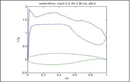
Figure 3.10 Pressure distributions for the modified airfoil with a control point A vertical displacement of +5 mm ...39
Figure 3.11 Local dynamic pressure over the flexible skin estimation by calculating the area integral under the Q values plot ...39
Figure 3.12 Turbulent signal of wind flow recorded in 1 sec sampled at 5 kHz (up), and the same signal at 3 seconds later (down) [7] ...43
Figure 3.13 Image of the transition from laminar to turbulent flow evidenced by fluorescent oil in UV light on the upper surface of a wing model with NACA 4415 airfoil in IAR-NRC wind tunnel ...46
Figure 3.14 Validation of the wind tunnel tests transition detection using XFoil code, which predicts the xtr position and the estimated frequencies of the turbulent flow ...47
Figure 3.15 The dynamic pressure distribution on the airfoil upper surface ...48
Figure 3.16 Measurements using microphones in wind tunnel of the transition occurrence over an airfoil [11] ...52
Figure 3.17 Wing model design realised in CATIA by LAMSI team [12] ...54
Figure 3.18 Optical and Kulite sensors distribution on the flexible skin, view from below realised in CATIA ...54
Figure 3.19 Mechanical principle of the SMA actuators ...55
Figure 3.20 The SMA S-function numerical model used in Simulink ...56
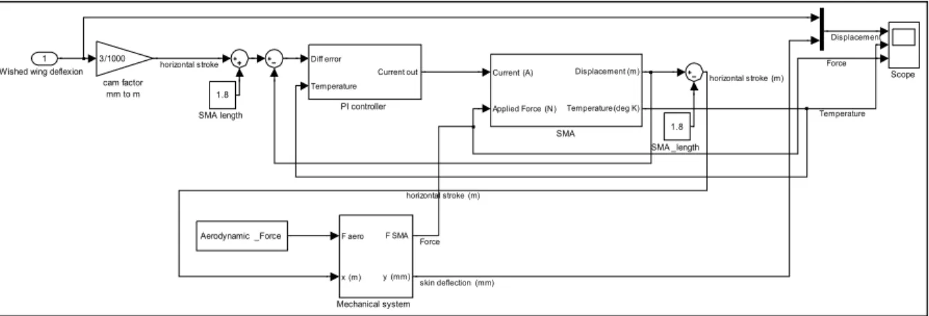
Figure 3.21 Schematic of the PID controller, SMA actuator and mechanical system ...57
Figure 3.22 Schematic of the PID controller, where P=1800, I=400, D=0 ...58
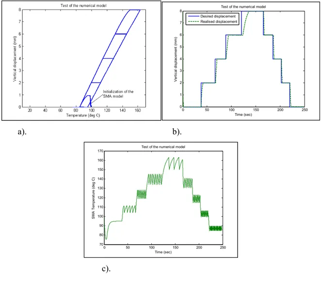
Figure 3.23 Test of the numerical model for a step of 0, 2, 4, 6, 8 mm in the absence of aerodynamic forces ...59
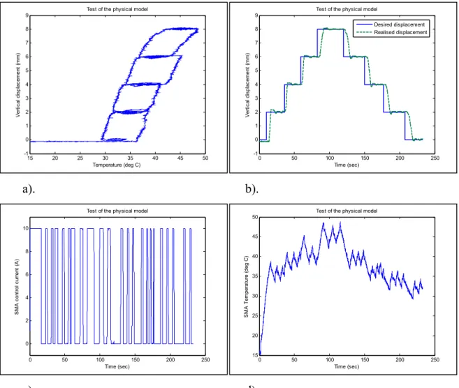
Figure 3.24 Controller bench test performed in closed loop using the potentiometer signal as feedback for actuator position ...60
Figure 3.25 Control schematic of the wing model in wind tunnel conditions
(the plant) using the optical sensors pressure signal as feedback signal. ...61 Figure 3.26 Model of the flexible skin using B-Splines compared to the finite element
results obtained in Nastran-Patran, the reference airfoil and optimised
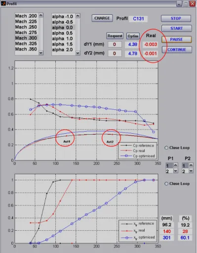
airfoil for the case C149 ...64 Figure 3.27 Results simulation for the airflow condition case C131 with the two
actuators at the zero positions (0 mm). ...65 Figure 3.28 Results simulation for the airflow condition case C131 with the two
actuators at the same positions as the two optimised airfoil control points ...67 Figure 3.29 Results simulation for the airflow condition case C131 with two
actuators controlled by a PID controller, so that the mean pressure coefficient is maintained at the same value as the optimised pressure coefficient corresponding to the 6th and the 13th optical sensors selected
in the menu on the right of the figure ...68 Figure 4.1 Closed-loop flow control (with optical sensors and feedback) of the
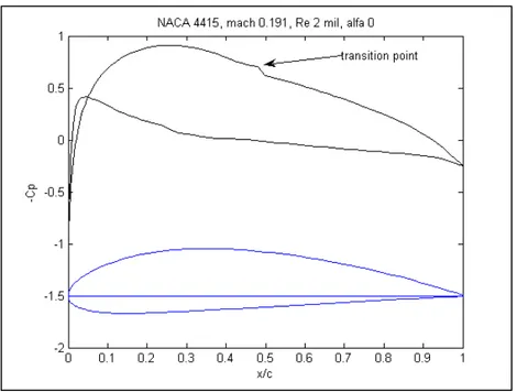
morphing wing design in a wind tunnel ...75 Figure 4.2 Pressure distribution and XFoil predicted transition point on the NACA
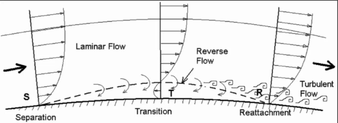
4415 airfoil at M = 0.191, Re = 2 × 10⁶, and α = 0 deg ...77 Figure 4.3 Schematic of the velocity distributions in the laminar separation bubble ...78 Figure 4.4 Cp distributions on a NACA 4415 airfoil at M = 0.3 and Re = 3 × 10⁶,
obtained using the XFoil code ...80 Figure 4.5 Cp distributions that correspond to a WTEA-TE1 reference airfoil and
to its modified shapes using a single control point, which creates a bump or depression on the airfoil ...82 Figure 4.6 Cp distributions in the vicinity of the transition point interpolated using the
Spline and PCHIP methods ...84 Figure 4.7 Second derivative of the Cp distribution interpolated using the Spline and
PCHIP methods ...84 Figure 4.8 Cp distributions on the upper and lower surface of the WTEA-TE1 airfoil
at a) α=0 deg and at b) α=1 deg ...85 Figure 4.9 Cp(x) at a) α = 0 deg and at b) α= 1 deg by use of Spline and PCHIP
Figure 4.10 Second derivative of Cp at a) α = 0 deg and at b) α= 1 deg by use of Spline
and PCHIP methods ...86
Figure 5.1 Controller closed loop scheme ...98
Figure 5.2 WTEA-TE1 reference airfoil and its modified airfoils shapes ...99
Figure 5.3 Details of block 2: determination of the pressure coefficients vs. the chord and transition point position [8]. ...100
Figure 5.4 Pressure coefficients vs. the chord computed by XFoil and the transition point position calculated by the new algorithm for Mach 0.2 and α = -2 deg ...101
Figure 5.5 Pressure coefficients vs. the chord computed by XFoil and the transition point position calculated by the new algorithm for Mach 0.2 and α = 0 deg ...101
Figure 5.6 Pressure coefficients vs. the chord computed by XFoil and the transition point position calculated by the new algorithm for Mach 0.2 and α = 2 deg ...102
Figure 5.7 Details of block 4: SMA ...104
Figure 5.8 SMA model scheme ...104
Figure 5.9 SMA cycle ...105
Figure 5.10 Identification of the SMA’s transfer functions ...107
Figure 5.11 Temperature and actuator displacement vs time with the SMA model compared with the corresponding transfer functions ...108
Figure 5.12 Displacement of the actuator vs. time with the ZN method ...109
Figure 5.13 Actuator displacements vs. time with the IMC method for several τc ...110
Figure 5.14 Displacement of actuator vs. time with the ZN and IMC methods ...112
Figure 5.15 Algorithm for SMA control improvement ...113
Figure 5.16 Displacement of the actuator vs. time with the new algorithm ...114
Figure 5.18 First simulation type results ...116 Figure 5.19 Second simulation type results ...118 Figure 5.20 Third simulation type results ...120 Figure 6.1 Positions of the sensors on the upper surface airfoil during a wind-tunnel
test ...129 Figure 6.2 Gage pressure signals recorded by optical sensors and pressure taps during
29 s ...130 Figure 6.3 Differential pressures between gage pressures measured by optical sensors
OS and gage pressures measured by pressure taps PT ...131 Figure 6.4 Static air temperatures variations during 21 runs in the Wind Tunnel ...131 Figure 6.5 Pressure coefficients distribution plotted over the wind-tunnel model
airfoil’s upper surface ...136 Figure 6.6 Visualization of relative errors of optical sensors versus pressure taps
during 21 runs in the wind tunnel ...138 Figure 7.1 Schematics of the flexible skin mechanical actuation, showing the
mechanical principle of morphing ...147 Figure 7.2 Measured by Kulite transducers vs. theoretical XFoil Cp values over the
upper surface of the reference airfoil ...149 Figure 7.3 FFT spectral decomposition of the 16 Kulite sensors channels ...150 Figure 7.4 Measured by Kulite transducers vs. theoretical XFoil pressure coefficient
values over the upper surface of the optimized airfoil ...151 Figure 7.5 FFT spectral decomposition of the 16 Kulite sensors channels ...152 Figure 7.6 Temperature map using infrared camera on the upper surface of the model
for a flow of Re = 2.55 × 10⁶, Mach = 0.224 and α = - 0.53 deg ...154 Figure 7.7 Measured by Kulite transducers vs. theoretical XFoil Cp values over the
upper surface of the model for airflow of Re = 2.55 × 10⁶, Mach = 0.224 and angle of attack = - 0.53 deg ...155
Figure 7.8 Temperature map using infrared camera on the upper surface of the model
for a flow of Re = 2.55 × 10⁶, Mach = 0.225 and α = 0.97 deg ...156
Figure 7.9 Measured by Kulite transducers vs. theoretical XFoil pressure coefficient values over the upper surface of the model for airflow of Re = 2.55 × 10⁶, Mach number = 0.225 α = 0.97 deg ...156
Figure 8.1 Schematics of the flexible skin mechanical actuation ...162
Figure 8.2 SMA control architecture during the bench test ...162
Figure 8.3 Simulink controller schematics ...163
Figure 8.4 Theoretical reference and optimized airfoils compared to scanned airfoils in bench test ...164
Figure 8.5 Time histories and temperature displacement diagram of case C127 morphing airfoil in bench test ...165
Figure 8.6 Time histories and temperature displacement diagram of case C135 morphing airfoil in bench test ...166
Figure 9.1 Closed-loop morphing wing system ...173
Figure 9.2 Structure of the actuating system with SMAs ...175
Figure 9.3 dY1 and dY2 as functions of M for various α ...176
Figure 9.4 Model of the flexible structure designed by LAMSI ...177
Figure 9.5 SMA control architecture and sensor acquisition systems of the test in a wind tunnel for the morphing wing model ...178
Figure 9.6 Pressure sensor distributions on the morphing wing airfoil ...180
Figure 9.7 PID controller results for run 33 ...182
Figure 9.8 Self-tuning fuzzy controller results for run 42 ...183
Figure 9.9 Ladder command for SMA actuators using self-tuning fuzzy controller ...184
Figure 9.10 Airflow case C124, M=0.275 and α = 2o ...185
Figure 9.12 Airflow case C129, Mach number = 0.3, α = - 1 deg, reference (original) airfoil ...188 Figure 9.13 Airflow case C129, M = 0.3, α = -1o optimized (morphed) airfoil ...189 Figure 9.14 2-D Wing Model in normalized coordinates (chord c = 0.5m). Morphing
portion of the wing at 0 < x/c < 0.7. Region measured by IR highlighted in red at 0.69 < y/c < 1.46. The rigid part of the wing, made of aluminum, is not used in the IR data. Flow is from left to right ...190 Figure 9.15 Infrared images at M = 0.3, α = -1° for two wing shapes: a) Reference and
b) Optimized shape C129. Transition location indicated with the red arrow. Flow is from left to right ...191 Figure 9.16 Infrared images at M = 0.275, α = 0° for two wing shapes: a) Reference
and b) Optimized shape C124. Transition location indicated with the red arrow. Flow is from left to right ...191 Figure 10.1 Cross section of the morphing wing model ...196 Figure 10.2 Two examples of optimized airfoil shapes for the aerodynamic cases C127
(M=0.275, α=1.5º) and C130 (M=0.3, α=-0.5º) ...198 Figure 10.3 Schematics of the flexible skin mechanical actuation ...199 Figure 10.4 Architecture of the morphing wing model control system ...200 Figure 10.5 FFT decomposition of the twelve channels pressure signals showing the
transition development in the boundary layer over the morphing wing
upper surface ...203 Figure 10.6 Graphical User Interface (GUI) where all the aerodynamic and morphing
shape information is centralized together with the control buttons of the
software ...204 Figure 10.7 Open loop control using optimized airfoils database and actuator positions
as feed-back ...208 Figure 10.8 Closed loop control using optimized airfoils database and Cp values as
feed-back ...209 Figure 10.9 Reference airfoil versus C226 airfoil results for M = 0.275. and α = 1°
Figure 10.10 C232 airfoil results obtained in a) Open loop, b) Closed loop control ...212
Figure 10.11 C232 airfoil results obtained at M = 0.3 and α = 0.5 in a) Open loop, b) Closed loop ...215
Figure 10.12 C232 infrared results obtained at M = 0.3 and α = 0.5° in a) Reference, b) Open loop control, c) Closed loop control ...216
Figure 11.1 Cross section of the morphing wing model ...222
Figure 11.2 Schematics of the flexible skin mechanical actuation ...225
Figure 11.3 Architecture of the morphing wing model control system ...226
Figure 11.4 Graphical User Interface (GUI) where all the aerodynamic and morphing shape information are centralized together with the control buttons of the software ...228
Figure 11.5 Optimization logic schematic ...230
Figure 11.6 Optimization in simulation using XFoil code a) and b) vs. optimization in real time during wind tunnel tests c) and d) for the same airflow conditions M = 0.25 and α = 0.5°. ...233
Figure 11.7 Optimization simulation result of xtr = 0.497 for dY1 = 3.3 mm and dY2 = 7.2 mm ...234
Figure 11.8 Optimization result of xtr /c = 0.635 (xtr =317.5 mm) for dY1 = 2.6 mm and dY2 = 5.1 mm during wind tunnel test for M = 0.25 and α = 0.5°...235
Figure 11.9 Optimization time history during wind tunnel test for M = 0.25 and α = 0.5° ...236
Figure 11.10 Infrared results obtained at M = 0.25 and α = 0.5° in a) Reference, b) After optimization ...237
ABREVIATIONS
CFD Computational fluid dynamics
CRIAQ Consortium for Research and Innovation in Aerospace in Quebec ETS École de téchnologie supérieure
FFT Fast Fourier transform
IAR-NRC Institute for Aerospace Research - National Research Council Canada IMC Internal method of control
LAMSI Laboratory of shape memory alloys and intelligent systems
LARCASE Laboratory of research in control avionics and aero-servo-elasticity LFC Laminar flow control
LVDT Linear variable differential transducer
NSERC National Sciences and Engineering Research Council of Canada PID Proportional integrative derivative controller
RMS Root mean square, standard deviation of a noised signal SMA Shape memory alloy
SPL Sound pressure level
WTEA-TE Wind tunnel experimental airfoil with modified trailing edge
SYMBOLS AND MEASURING UNITS
a Speed of sound
b Span of wing model
c chord of wing airfoil
e Error
f Frequency
ft Foot
i Current in the shape memory alloy
k Adiabatic coefficient of air
kHz Kilo Hertz
kS/s Kilo samples per second lb Pounds
lbf Pounds force
m Meter m/s Meter per second
p Static pressure
pabs Absolute pressure
pgage Gage pressure
p0 Total pressure (stagnation pressure)
p1 Inflow static pressure
psi Pounds per square inch
q Dynamic pressure
u Local airflow velocity in x direction
v Local airflow velocity in y direction
x Stream wise distance from airfoil leading edge
y Perpendicular distance on the upper surface of the airfoil
A Amplitudes of perturbations
Cp Pressure coefficient =
(
p p− ∞)
/q∞ =(
p p− ∞)
/ 0.5ρU∞F Applied force on the shape memory alloy
G Transfer function
GPa Giga Pascal
K Static gain of the proportional integral derivative
Kc Critical gain of the proportional integral derivative
Kd Derivative gain of the proportional integral derivative
Ki Integral gain of the proportional integral derivative
Kp Proportional gain of the proportional integral derivative
L Length reference
M Mach number
N Natural logarithm of rapport between amplified perturbation and initial perturbation in laminar flow N factor = ln (A/A0)
Ncr N critical, the value of N when transition between laminar and turbulent flow
occurs
Pa Pascal (N/m2 Newton per square meter)
Tc Critical period of the shape memory alloy model
Ti Initial temperature in the shape memory alloy
U Input of a transfer function
U∞ Free stream airflow speed in wind tunnel
V Airflow speed
Y Exit of a transfer function
α Angle of attack of the wing
µ Air viscosity
ρ Air density
σ Turbulence intensity
τ Turbulence level
τc Controller delay of the proportional integral derivative controlling the shape memory alloy model
τ1 Time delay of the proportional integral derivative controlling the shape
memory alloy model
τ2 Time delay of the proportional integral derivative controlling the shape
memory alloy model
τ3 Dead time of the proportional integral derivative controlling the shape
INTRODUCTION
Today, aeronautical transport is evolving at a very fast pace, as compared to the beginning of the aviation era; aeronautical traffic tripled during the last fifteen years, and by 2025, is projected to double from today’s levels. This traffic is expected to see an estimated +3.0% increase in the number of passengers per year, to approximately 1 billion by 2016; will be accompanied by a load factor increase of 81.7% as compared to today’s values by 2025 [1]. This evolution will need the new technologies development in the design and building of modern aircraft equipped with active control systems.
During the same time period, fuel cost increases will lead to a slowdown in the aerospace industry, which in turn will stimulate research to find technological solutions; this will specifically involve designing new fuel economy consumption methods. A new green trend has indeed started to spread out from the automobile industry into the aircraft industry, in which research is being carried out to reduce fuel consumption by reducing drag, which is directly related to the airflow type around the aerodynamic aircraft body design. The drag reduction concept is connected to the laminar flow and to the displacement of the transition point between laminar and turbulent flows towards the trailing edge.
Numerous studies, which will be detailed in the Chapter 1, show that the transition between laminar and turbulent flows is influenced by the shape of the wing airfoil, which will be our main focus in this research project. Aerodynamic studies from the beginning of the aviation history show that for a certain flight condition characterized by a given Mach number and a given Reynolds number, the airflow around a wing airfoil is laminar at the leading edge, but becomes turbulent at a certain point due to air viscosity. A turbulent flow is not desired because of its negative effect in terms of drag increase, which, over time, leads to high fuel consumption, and consequently, increased operating costs.
This research thesis is realized as part of a major project initiated and financially supported by following government and industry associations: the Consortium for Research and
Innovation in Aerospace in Quebec (CRIAQ), the National Sciences and Engineering Research Council of Canada (NSERC), Bombardier Aerospace, Thales Avionics and the National Research Council Canada Institute for Aerospace Research (NRC-IAR).
The project aims to realize a theoretical and experimental aerodynamic wind tunnel study of a rectangular wing equipped with a flexible skin, smart actuators and optical sensors, able of changing its shape using an active controller, in order to move the position of transition from laminar to turbulent flow.
This multidisciplinary project is realized by several collaborating teams from the École de technologie supérieure, the Laboratory of Memory Alloys and Intelligent Systems (LAMSI), the Laboratory of Research in Avionics and Aero-Servo-Elasticity (LARCASE), École Polytechnique, the National Research Council Canada Institute for Aerospace Research (NRC-IAR), Thales Avionics and Bombardier Aerospace.
The teams were each assigned the following responsibilities in the project, respectively: the LAMSI team was charged with designing and manufacturing the actuators and flexible skin as well as the model internal structure; the École Polytechnique team had the responsibility of designing the optimized airfoils for each airflow condition using CFD codes in order to analyze the transition from laminar to turbulent flow; the NRC-IAR team had to organize and run the wind tunnel tests, while the LARCASE team was responsible for the integration and validation of the control and monitoring systems of the morphing wing model.
As a member of the LARCASE team, my thesis will focus on the aspects of the research involving the integration and functional validation of the various mechanical and electrical systems that composed the morphing wing model.
The thesis includes the chapters on the: 1) state-of-the-art in the morphing aircraft research domain, 2) objectives and originality, and 3) collection of eight articles published in the
chronological order (from the oldest to the newest), in which the research work performed to reach the project objectives is shown.
The eight articles are: the first three articles published in the AIAA Journal of Aircraft, two articles presented at two aeronautical conferences and the last three articles accepted for publication and in print in the AIAA Journal of Aircraft.
These articles are written in collaboration with my colleagues at the LARCASE laboratory and members of other teams. My contribution as main author, as well as the contributions of colleagues of the other teams to each article is specified in the introductory part of each article. Dr Botez is the co-author of these papers, as PhD advisor.
The thesis concludes with a short list of recommendations to be followed in future research on morphing aircraft control.
In the first article, a new theoretical method of detecting the transition between laminar to turbulent flows is presented. The method uses a new algorithm based on interpolation methods programmed in Matlab, to localize the transition where the discontinuities in the pressure plot appear, for small angles of attack. It was intended, at that time, to use this new method in the future controller, as feedback information on the transition point position on the wing model upper surface.
In the second article, a new simulation method for the shape memory alloys actuators control through a PID controller is presented. This new method was functional in simulation and was further tested with hardware in the loop, on bench tests, and successfully presented in the fifth article.
In the third article, a new method for optical sensors calibration with temperature variations is presented. This new method could be applied in the case when the optical sensors do not have temperature compensation to be used in wind tunnel tests. The optical sensors were
intended to give feedback information about the transition point position on the upper surface of the wing model, but they were abandoned later in the project dues to technological reasons that are discussed in the fourth article introduction.
In the fourth article, a laminar-to-turbulent flow transition detection method is presented, and the way in which the signals were post processed in order to obtain the flow state information on the boundary layer. This method was finally implemented in the software controller as feedback information about transition point position and pressure information on the wing model upper surface.
In the fifth article, the bench test results are presented using the new control method developed. It was found that aerodynamic optimized theoretical airfoils are same as the scanned airfoils obtained on the real wing model during bench tests. The controller software tested on the bench was further used in the following wing tunnel tests, as shown in the last three articles.
The wind tunnel tests results are presented in the sixth article, and proved that the morphing wing concept would be feasible, and would provide great potential for the aerospace industry future. The wing model was controlled using the open loop control method. The shape memory actuators, high sensitivity pressure sensors and software controllers formed a system to be integrated and validated in the wind tunnel for the first time in this article.
In the following two articles, different control strategies are discussed, that can be used in the future morphing wing aircraft controllers. In the seventh article, the wind tunnel tests results of the wing model controlled using the loop control method, are shown. The closed-loop control method results were compared and thus validated with the open closed-loop control method results, and were validated using the infrared thermography.
A new optimization method is shown in the eighth article, for the closed loop controller, and the wing model as real time hardware-in-the-loop in running wind tunnel conditions. The experimental results were successfully validated with simulation results.
Reference
[1] Nan Shellabarger, 2008, “National Forecast Overview 2008-2025”, Director Aviation Policy and Plans, Federal Aviation Administration.
http://www.faa.gov/news/conferences_events/aviation_forecast_2008/agenda_presentat ion/media/nan_shellabarger.pdf . Consulted November 6, 2009.
CHAPTER 1
STATE OF THE ART
In this chapter, a brief state of the art in the morphing aircraft research domain is presented. Firstly the laminar flow improvement literature will be described using only aerodynamics knowledge, then morphing wing control methods using only actuators, followed by materials and actuation use in the morphing wing design, and finally the integrated morphing wing and aircraft studies realised until now.
1.1 Aerodynamic methods for laminar flow improvement
To modify the laminar flow around a wing airfoil, it was necessary to change the airfoil shape; therefore one of the methods for airfoil changes was developed at Kentucky University, which consisted of deflecting the wing upper surface using adaptive actuators [1, 2, 3, 4, 5, 6] .
It was shown that the actuators activated oscillatory motions of a certain frequency to the boundary layer flow over the upper surface. These actuators were made of piezo-electric materials which changed their shapes when connected to an electrical current differential voltage. The wind tunnel tests showed that the displacement of the transition point to the trailing edge resulted in the drag decrease and in the lift increase [2].
Another method for changing the airfoil shape involved the use of a bump, which was inflated with air. This method was conceived by researchers at Stuttgart University [7, 8]. In this method, the airfoil geometry was modified in order to decrease the negative effects of shockwaves in transonic flow. The results obtained by the airfoil optimization showed a 70% decrease in the wave drag and a 15% decrease in the wing total drag.
At the German Aerospace Research Center (DLR), researchers simulated the changes of the airfoil shape using an inflated bump [10, 11]. The results obtained showed a 10% drag
reduction for Mach numbers between 0.72 and 0.77. A basic theory was developed for changing the airfoil shape in transonic flow.
Another method for changing the airfoil shape was studied by the Aerospace Company Embraer [12, 13, 14, 15]. In this case, the leading and trailing edges changed their shapes by curving the camber line. The results obtained by Embraer were promising as they showed a reduction in drag value by up to 24%.
A 1991 study conducted at NASA’s Langley laboratory evaluated the application of the hybrid laminar flow control (HLFC) on subsonic aircrafts and bi-motor aircraft transporters [9, 16]. The study was realized by using the FLOPS optimizing flight system as well as a CFD code. The researchers studied the laminar flow over the upper surface of the wing, and over the vertical and horizontal stabilizers. They also studied the advantages of the laminar flow over the nacelles.
The “chordwise air collection” method was designed in 1984 [17], in fact, laminar flow control (LFC) over the upper surface of the wing was realized by the boundary layer suction, thereby moving the transition position at 85% of the chord.
A numerical algorithm was developed for optimizing the suction distribution, by maintaining the transition at a desired location (chord %) and maintaining the energy spent at a minimum [18]. Three steps were considered: 1. Boundary layer computation; 2. Transition prediction, and 3. Optimization of the suction distribution while maintaining the transition location at a certain desired percentage of the chord. In the third step, the gradient method was used. Optimized wings were conceived by reducing the kinetic energy of the perturbation and drag values while, the lift and pitch moment coefficients were maintained at desired values [19].
At the German Aerospace Research Center (DLR), the DoAL3 airfoil was designed for aircraft wings, at moderate Mach numbers, M = 0.45-0.6, and at Reynolds numbers, up to Re = 14 × 106. Transition measurements were performed in the Brunswick Wind Tunnel (TWB)
at Mach number of 0.48. The effects of Reynolds number and the thermal transfer on the laminar flow separately were studied, and the numerical results were validated by experiments.
A controller was developed at Southampton University, with the aim of maintaining the desired turbulence level over a flat plate equipped with a suction porous panel. The pressure fluctuations were measured with microphones at the boundary layer over the flat plate, and the signal was conditioned and filtered to remove the background noise of the wind tunnel fan, then the turbulence level was estimated by computing the RMS (Root Mean Square) pressure signal. The controller used the error between the RMS values of the measured pressures and the desired RMS values at the spots where the microphones were installed, thus maintaining the transition on the specified area over the flat plate [20].
1.2 Morphing wings equipped only with actuators
Three devices were able of modifying wing structure on a test bed aircraft [21]. The first device was the Hyper-Elliptic Cambered Span (HECS) wing mechanism – used to increase loiter time. During cruise, induced drag accounted for 50% of the total aircraft drag. Compared to a planar elliptic wing of the same span, the HECS wing provided a lift-to-drag ratio (L/D) increase of as much as 15%, with a 10% increase in surface area. The second device was the oblique joint mechanism, located at the root of a standard planar elliptical airfoil, and capable of independently rotating each wing on an aircraft through variations of dihedral, sweep and incidence angles, by use of three sequential motors per wing that can be operated independently. The third device employed a Stewart platform concept as a constrained version of the 6 degrees of freedom mechanism commonly used, with a central pivot preventing translational motion and allowing rotation about the center of the top and bottom plate using 3 Haydon Switch and Instrument ½ stroke linear actuators. Compliant skin materials were also discussed.
A strain energy model took into account the actuation cost of a morphing airfoil, where a multi-objective optimization found trade-off solutions between low-energy/high drag and
high energy/low drag morphing airfoils [22]. The aerodynamic work term was added to the strain energy model to compute the total energy required for the airfoil shape change. The effect of the morphing airfoil’s relative stiffness on the multi-objective solutions was presented.
Stabilators were used for various applications such as primary and secondary flight control, buffet-load alleviation, flutter testing, active flow reattachment and vortex generation. Although most of the adaptive aerostructures applications were found in UAV’s, missiles and munitions [23].
Closed-loop control of the morphing platform (wing-shape control) and simultaneously enforced prescribed closed loop aircraft dynamics (flight control) were modeled [24]. The
N-MAS wing designed by NextGen Aeronautics was considered. The flight control law actively
used the leading edge morphing wing sweep angle as an actuator to assist in manoeuvres while guaranteeing aircraft stability. An aircraft model (morphing wing, aircraft body, and control surface locations) was developed using CAD drawings, mass and geometry specifications and NACA airfoil designations. The Simulink model included variable Center of Gravity- (CG) and DATCOM-derived aerodynamic coefficients as a function of the wing configuration and angle of attack. The morph between the two modes of Loiter and Dash was modeled by a first-order transfer function, and hence the morph rate was governed by the transfer function time constant.
The empirical structural weights for various wing geometries were obtained by implementing two finite element-based structural optimization methods: 1) an aggregate and 2) a simultaneous analysis [25]. These methods were applied on a morphing wing with two degrees of freedom: the wing sweep and the root chord length. Two linear actuators were used: one positioned along and parallel to the forward spar and the other one positioned along and parallel to the wing root chord. These geometrical variations produced four configurations with changes in area, aspect ratio and sweep: the high lift configuration for the largest area and minimal sweep angle; the loiter configuration for the maximum aspect
ratio and minimum sweep angle; the dash/cruise configuration for the maximum sweep and minimal area; and the manoeuvre configuration for the maximum area at the maximum sweep.
1.3 Materials and actuators use in the morphing wing design
Various types of materials were used in the morphing wing design, such as:
Computational materials with high performance, such as continuous fibre-reinforced
polymer matrix composites and piezoelectric films from high temperature polyimides [26],
advanced piezoelectric materials, such as piezoelectric polymers, high displacement
piezoelectric ceramic actuators and ferroelectric thin film micro-actuators and integrated and
graphite reinforced composites.
Morphing actuators’ failure compensations, called effectors, were investigated as they
replaced control surfaces such as ailerons or rudders on a morphing wing [27].
Flexible material structures enabled large rigid body deformations of aircraft structures while maintaining their aerodynamic shapes. Matrix material was selected to be a Shape Memory Polymer SMP embedded with a reinforcing fibre [28, 29].
An adaptive actuator failure compensation control scheme was completed for the state tracking of a morphing aircraft model with unknown morphing actuator failures [30].
A device allowed most of the energy required to twist or deform a wing to be stored in discrete springs. When the device was used, sufficient energy was provided to control the wing position. Lightweight actuators were used to perform wing twisting and other structural distortions, and reduce the onboard mass of the wing-twist system [31].
Post-Buckled and Pre-compressed PBP piezoelectric actuators induced roll control on a subscale morphing wing. Aerodynamic wing loading was modeled using Theodorsen’s
theory of disturbed flow. Bench tests showed a maximum deflection of more than +/- 3 degrees up to a break frequency of 34 Hz. Application of PBP actuators led to savings in
Operating Empty Weight (OEW) of 3.5% and an increase in break frequency from 3 to 34 Hz
[32].
Strain actuators embedded in the structure or strategically distributed modern miniaturized actuators were conceived and verified [33].
Shape memory alloys (SMA) used in morphing flaps actuation were developed in ultra-light
and scaled models made of balsa wood and nylon sticks, dues to favourable characteristics of high strength and low weight. The SMA actuators were controlled using robust non-linear controllers [34, 35].
Wind tunnel studies on morphing wing flaps prototypes using SMA wires (NiTiNol) were performed at the Missouri University of Science and Technology. The trailing edge was morphed by means of six NiTiNol wires that could pull the flaps assembly upon electrical activation, while ten springs acted to regain the initial wing configuration when the SMA wires cooled down [36].
Another morphing flap actuated using SMAs was developed at Nayang Technological University, Singapore using four SMA wires anchored in four different chord points. A wing prototype with flexible skin made of fibreglass composite and rubber sheet was manufactured and tested [37].
Torsion bars and wires using SMA (NiTiNol) for the roll control of a morphing wing model aircraft were tested in wind tunnel and during flight at the Virginia Polytechnic Institute and State University [38].
The “Hingeless Wing” concept using SMA wires was investigated at the Aerospace Engineering Department (DIAS) at University “Federico II” of Naples, in collaboration with the Italian Aerospace Research Center (CIRA) [39], and independently at the University of Catania (Italy) [40].
1.4 Integrated morphing wing studies
Mission Adaptive Compliant (MAC) Wing Technology allowed linearly varying flap deflections along the wing span. The main benefits consisted of allowing the flap to reshape the wing lift distribution closer to an elliptical distribution, thus minimizing induced drag and wing root bending moment, and thereby saving weight [41].
Northrop Grumman Corporation (NGC) has built and tested two 16% - scale wind tunnel models (conventional and smart) of a fighter aircraft under the DARPA/AFRL/NASA Smart Wing Phase I project [42]. Hinge-less, contoured TE control surfaces with embedded SMA wires and span-wise wing twists effected by SMA torque tube mechanisms were compared to the conventional hinged control surfaces. Benefits were expressed in terms of increased pitching and rolling moments, and improved pressure distributions. Successful results were expressed in terms of: 5 degrees of span-wise twist and an 8-12% increase in rolling moment using a single SMA torque tube, 12 degrees of deflection and 10% increase in rolling moment, and in demonstration of optical techniques for span twist and deflected shape measurements.
A symmetric wing structure was created with two tapered graphite/epoxy composite plates and a steel body. Four pairs of SMA wires were attached to the wings’ bottom surfaces in the chord-wise direction. Lift and drag forces were measured at various angles of attack. Dynamic vibration signals were measured by Fiber Bragg Grating FBG sensors at the wing root and were used to monitor aeroelastic unstable flutter phenomena, at various angles of attack [43].
A wing structure comprised of an optimized internal layout of cables and struts was able to change its shape. Cables were used as actuators’ tendons, while struts provided rigidity to the wing. In addition to achieving continuous morphing by changing cable lengths, this structure had the advantages of being light weighted and having a distributed actuation. Topology optimization was used to optimally place cables and struts in a bay or in a wing section. The
Non-dominated Sorting Genetic Algorithm II (NSGA II) was used for modeling the NASA
HECS and the NextGen TSCh wings [44].
An integrated multi-disciplinary optimization procedure for morphing wing optimization was mainly based on ‘off-the-shelf’ analysis codes. It allowed the computation of the minimum structural weight of morphing wings (for which swept angle and aspect ratio change). This optimization was performed with a general-purpose optimization code, called Optimus, distributed by Noesis Solutions. For aeroelasticity studies, MSC/Nastran and ALIS (for steady and unsteady linear aerodynamics) codes were used. Two approaches were presented:
sequential and fully integrated. An LMS Virtual Lab Morphing tool was also used [45].
Wings roll performances were achieved by use of articulated conformal control surfaces. Analysis results were compared to experimental results obtained for a 16% scale model of a fighter wing equipped with embedded smart materials used to deform a control surface. The control surface design was found suitable for low-rate applications such as takeoff and
landing configurations [46].
1.5 Integrated morphing aircraft studies
Lockheed Martin has built an Unmanned Combat Air Vehicle UCAV for Morphing A/C studies. Its configuration had two folds that allowed the radical morphing of the span and wetted area. The multi-role aerodynamic performance was defined by a combination of cruise/loiter efficiency and dash/penetration capability in a single vehicle, and by significantly increasing the mission performance with respect to the conventional platforms. Both inboard and outboard flaps were required for manoeuvring and pitch/yaw stability [47].
An articulated large-scale half span wind tunnel model-validated morphing system operation under realistic flight loads was realized [48].
Four application fields of the SMA’s technology on an aircraft have been investigated: vibration/acoustic control, shape control, multi-functional smart structures, and morphing structures. Tail-buffet suppression, flutter damping, engine-vibration control, smart wing, smart skin, adaptive Micro Air Vehicle (MAV), vortex wake control and biology-inspired aircraft were reviewed. The best technology application would be a reconfigurable configuration for which performances would be adjusted and optimized under varying conditions [49].
The MFX-1, created under a DARPA sponsored program called Next Generation Morphing A/C Structures (N-MAS) and realized by Next-Gen Aeronautics, had a 9.3 ft wing span, a length of 6.8 ft, V-tails, nretractable landing gear with a steerable nose wheel, three on-board cameras with one download link and a GPS system. It was powered by a single jet engine with 45 lbs of maximum thrust. Other key features included: independently activated ailerons, flaps, rudders, GPS, MEMS gyros and accelerometers as flight control system sensors, altitude telemetry, airspeed, GPA headings, and battery conditions, maximum flight time of 20 minutes and a parachute flight termination/recovery system. The primary purposes of these tests were to (1) demonstrate in-flight operation at sub-scale, and stability and control of the MFX-1; and (2) test flight test procedures including communications and pilot skills for N-MAS aircraft.
During the first test, a fixed wing was flown, which provided good training for the flight test crew. During the second test, performed on the morphing wing, multiple checks of the morphing wing actuation and power systems were performed prior to flight to reduce the overall test risk [50]. The flight took place at altitudes between 400 and 600 ft, and at speeds between 100 and 120 knots. The remote pilot had no cues except aircraft views from the ground. Onboard recorded data included GPS location and altitude; and three video cameras, mounted on the twin tails of the aircraft and in its nose, provided flight pictures to be
downloaded after landing. The wing area changed 40%, the wing span changed 30%, and the wing sweep varied from 15º to 35º to successfully morph during flight, of less than 15 seconds. During Phase II of the NMAS program, a 200 lb, autonomous, twin-jet morphing UAV had a larger and improved wing design which rapidly morphed during manoeuvres required for agile Hunter-Killer operations.
The probabilistic modeling of actuator failure and stochastic robust control provided a novel and flexible means of failure compensation for a morphing tailless, delta-wing fighter aircraft operating arrays of large numbers of actuation devices [51]; Lateral equations of motion were linearised at Mach number M = 0.6 and altitude H = 15,000 ft. The equilibrium trim angle of attack was approximately 4.4 degrees. Control moments required at the trim condition were generated by conventional hinged surface actuators. The shape-change effectors/device arrays were used to stabilize and manoeuvre the vehicle at the trim condition. Among the four distributed arrays of shape-change devices on each wing, three are situated on the upper surface and one is on the lower wing surface. There were a total of 156 devices, 78 on each wing [51].
NextGen developed an in-plane morphing geometry concept. Flexible elastomeric skins with out-of-plane stiffeners accommodated the wing motion while transmitting air pressure loads to the wing substructure. Wind tunnel testing of a full-scale wing for a 2400 lb vehicle and flight testing of a subscale UAV were performed. The following issues were identified: the need to address multiple geometries and flight envelopes to account for morphing shape changes; the in-plane wing flexibility resulting from its mechanism restraint by linear actuators. Another half-span wind tunnel model was tested in the NASA Transonic Dynamics Tunnel for aeroelasticity studies [52].
The Miniature Trailing Edge effector (MiTE) was a small trailing edge device located at 1-5% chord, deflected vertically into the flow. A stable separation region ahead of the flap and a pair of counter-rotating vortices aft were realized. Aerodynamic analysis results provided a database for the development of the aerodynamic wind tunnel test model. The
aeroservoelastic test model successfully proved an Active Flutter Suppression concept for an UAV [53].
An aeroelastic numerical code took into account the morphing energy coupled of a 3D beam finite elements model in a co-rotational framework to a lifting line aerodynamic code. The morphing energy was calculated by the sum of actuation moments, applied at the beam nodes, multiplied by the required angular rotations of the beam elements. The code results were validated with Nastran Aeroelasticity Module. This code was tested for a sweep
morphing manoeuvre, and it was demonstrated that sweep morphing improved aircraft
aerodynamic performances such as the lift–to–drag ratio (L/D) values [54].
The Flight Test results of a Mission Adaptive Compliant Wing (MAC-Wing) variable geometry Ttrailing Edge Flap with a Natural Laminar Flow NLF airfoil have been described. The MAC-Wing technology provided light-weight, low power, variable geometry reshaping of the upper and lower flap surface with no discontinuities. The airfoil-flap system was optimized to maximize the laminar boundary layer extent over a broad lift coefficient range for endurance aircraft applications. The expanded laminar bucket capability allowed the endurance aircraft to extend their range, by 15% or more, by optimizing the lift-to-drag ratio (L/D) throughout the mission. The wing was tested at full-scale dynamic pressure, Mach number, and reduced-scale Reynolds numbers on Scaled Composites’ Knight Aircraft. Laminar flow regime occurred up to 60% chord of the wing during tests. Significant fuel and weight savings as well as high control authority were verified by tests and analyses. Fifteen Dantec Dynamics hot film sensors measured the boundary layer transition position [41].
The MORPHEUS wind tunnel model of a Morphing Air Vehicle (MAV) was designed for the following five purposes: quasi-steady aerodynamic modeling of an aircraft with large planform changes, optimization studies to achieve efficient flight configurations, transient aerodynamic modeling of high rate planform changes, planform manoeuvring evaluations as control effectors, and gimballed flight control simulation of a morphing aircraft [55].
In the Air-to-Air Fighter (AAF) model consisting of a propulsion subsystem (PS) and an Airframe Subsystem – Aerodynamics (AFS-A), the morphing wing was allowed to change its sweep, length, root and tip chord lengths within set constraints for its AAF mission of 19 flight segments. Using minimum fuel burned as an objective, the most efficient wing configuration and the overall aircraft system operation were achieved for each segment of the mission [56].
A DARPA-sponsored wind tunnel test model of a Lockheed Martin morphing concept was designed and tested. The wind tunnel model incorporated the key features representatives of a full scale vehicle model: out-of-plane morphing through a coordinated actuation system integrated with seamless skins and a composite support structure that encompassed the actuator system along the wing fold hinge lines, structural layout and materials featured in the full scale vehicle design, and a first-time thermo-polymer actuator integral to a leading edge device for smooth contour between the inner wing and fuselage when fully morphed. The model was instrumented with strain gauges, accelerometers and pressure transducers; data was acquired and correlated with aircraft design and analysis methods [57].
Following our detailed bibliographical research, it was realized that until now, nobody realized a fully automated morphing wing controller for the laminar flow improvement and further for transition delay using pressure sensors and Smart Material Actuators to morph its upper surface.
References
[1] Munday, D., Jacob, J., 2002, Active control separation on a wing with oscillating
camber, AIAA Journal of Aircraft, vol. 39 (1), Paper AIAA 2001–0293.
[2] Jacob, J. D., 1999, Aerodynamic flow control using shape adaptive surfaces asme, Paper No. DETC99/VIB-8323, ASME 17th Biennial Conference on Mechanical Vibration and Noise, Symposium on Structronics, Mechatronics, and Smart Materials, Las Vegas, Nevada, September.
[3] Munday, D., Jacob, J., 2001, Low speed morphing wing flow control, University of Kentucky, Lexington, KY.
http://www.engr.uky.edu/~fml/research/wing-2001.pdf, Consulted on November 6. [4] Munday, D., Jacob, J. D., and Huang, G., 2002, Active flow control of separation on a
wing with oscillatory camber, 40th AIAA Aerospace Sciences Meeting, Reno, NV.
Paper AIAA-2002-0413
http://www.engr.uky.edu/~fml/papers/AIAA-2002-0413.pdf, Consulted on November 6, 2009.
[5] Munday, D., Jacob, J. D., Hauser, T., and Huang, G., 2002, Experimental and
numerical investigation of aerodynamic flow control using oscillating adaptive surfaces, AIAA Paper No. 2002-2837, 1st AIAA Flow Control Conference, St. Louis.
http://www.engr.uky.edu/~fml/papers/AIAA-2002-2837.pdf, Consulted on November 6, 2009.
[6] Jacob, J. D., 1998, On the fluid dynamics of adaptive airfoils, University of Kentucky, Lexington,
http://www.engr.uky.edu/~fml/papers/imece-paper.pdf. Consulted on November 6, 2009.
[7] Lutz, T., Sommerer, A., Wagner, S., 2000, Design of adaptive transonic airfoils by
means of numerical optimisation, University of Stuttgart, Germany.
[8] Wadehn, W., Sommerer, A., Lutz, Th., Fokin, D., Pritschow, G., Wagner, S., 2002,
Structural concepts and aerodynamic design of shock control bumps, Proceedings 23nd
ICAS Congress, Toronto, Canada, September 8 - 13, ICAS Paper 66R1.1.
[9] Pinkerton, J. L., Moses, R. W., 1997, A feasibility study to control airfoil shape using
THUNDER, Langley Research Center, Hampton, Virginia, NASA Technical
Memorandum 4767.
[10] Sobieczky, H., Geissler, W., 1999, Active flow control based on transonic design
concepts , DLR German Aerospace Research Establishment, AIAA Paper 99-3127.
[11] Sobieczky, H., Geissler, W., Hannemann, M., 1998, Expansion shoulder bump for wing
section viscous/wave drag control, FLOWCON IUTAM Symposium on Mechanics of
Passive and Active Flow Control, Gottingen, Germany.
[12] Martins, A.L.; Catalano, F.M., 1996, Aerodynamic optimization study of a mission
adaptive wing for transport aircraft, ICAS-96, Sorrento, Italy.
[13] Martins, A.L., Catalano, F.M., 1998, Viscous drag optimization for a transport aircraft
[14] Catalano, F.M., Greco Jr, P.C., Martins, A.L., 2002, Viscous and wave drag
optimization for a transport aircraft mission adaptive wing, Aircraft Laboratory –
University of São Paulo-Brazil and Embraer, ICAS Congress.
[15] Martins, A. L., Catalano, F. M., 2003, Drag optimization for transport aircraft mission
adaptive wing, Journal of the Brazilian Society of Mechanical Sciences, vol. 25, no. 1.
[16] Arcara, P.C., Jr., Bartlett, D.W., McCullers, L.A., 1991, Analysis for the application of
hybrid laminar flow control to a long-range subsonic transport aircraft, SAE
Technical Paper Series, 912113, 1991, pages 1-15, Aerospace Technology Conference and Exposition, Sep 23-26, Long Beach, CA, USA.
[17] Allison, D.O., Dagenhart, J.R., 1978, Design of a laminar-flow-control supercritical
airfoil for a swept wing, CTOL Transport Technology, pages 395-408.
[18] Hackenberg, P., 1995, Numerical optimization of the suction distribution for laminar
flow control aerofoils, Doctoral Thesis, University of Southampton (United Kingdom).
[19] Pralits, J., 2003, Optimal design of natural and hybrid laminar flow control on wings, Doctoral Thesis, Technical Report from Royal Institute of Technology, Stockholm, Sweden.
[20] Rioual, J.-L., Nelson, P. A., Fisher, M. J., 1994, Experiments on the automatic control
of boundary-layer transition, Journal of Aircraft. Vol. 31, No. 6, pp 1416-1418.
[21] Manzo, J., Garcia, E., Wickenheiser, A., M., 2004, Adaptive structural systems and compliant skin technology of morphing aircraft structures, Proceedings of SPIE:
International Society for Optical Engineering, Vol. 5390, pp. 225–234. http://spie.org/x648.html?product_id=540348 [retrieved 8 January 2010]
[22] Namgoong, H., Crossley, W., A., Lyrintzis, A., S., 2006, Morphing airfoil design for
minimum aerodynamic drag and actuation energy including aerodynamic work, AIAA
Paper 2006-2041, pp. 5407–5421.
[23] Barrett, R., 2007, Improvements to commercial and general aviation via adaptive
aerostructures, Paper AIAA-2007-7873, 7th AIAA Aviation Technology, Integration
and Operations Conference (ATIO), 18-20 September, pp. 1-9.
[24] Gandhi, N., Jha, A., Monaco, J., Seigler, T., M., Ward, D., Inman, D., J., 2007,
Intelligent control of a morphing aircraft, Paper AIAA-2007-1716, pp. 166-182.
[25] Skillen, M. D., Crossley, W. A., 2005, Developing response surface based wing weight
equations for conceptual morphing aircraft sizing, Paper AIAA-2005-1960,
![Figure 3.12 Turbulent signal of wind flow recorded in 1 sec sampled at 5 kHz (up), and the same signal at 3 seconds later (down) [7]](https://thumb-eu.123doks.com/thumbv2/123doknet/7696451.244799/63.918.212.785.158.587/figure-turbulent-signal-recorded-sampled-signal-seconds-later.webp)
![Figure 3.16 Measurements using microphones in wind tunnel of the transition occurrence over an airfoil [11]](https://thumb-eu.123doks.com/thumbv2/123doknet/7696451.244799/72.918.348.653.156.476/figure-measurements-using-microphones-tunnel-transition-occurrence-airfoil.webp)
![Figure 3.17 Wing model design realised in CATIA by LAMSI team [12]](https://thumb-eu.123doks.com/thumbv2/123doknet/7696451.244799/74.918.175.826.288.601/figure-wing-model-design-realised-catia-lamsi-team.webp)