Wireless Power Charger System for Mobility Scooter
by
Nelcy Pahola PORRAS RODRIGUEZ
THESIS PRESENTED TO ÉCOLE DE TECHNOLOGIE SUPÉRIEURE IN
PARTIAL FULFILLMENT FOR A MASTER’S DEGREE WITH THESIS IN
RENEWABLE ENERGIES AND ENERGY EFFICIENCY.
M.A.Sc.
MONTRÉAL, JULY 20, 2020
ECOLE DE TECHNOLOGIE SUPÉRIEURE
UNIVERSITÉ DU QUÉBEC
This Creative Commons licence allows readers to download this work and share it with others as long as the author is credited. The content of this work can’t be modified in any way or used commercially.
BOARDOFEXAMINERS THISTHESISHASBEENEVALUATED BYTHEFOLLOWINGBOARDOFEXAMINERS
Mr. Kamal AL-HADDAD, Thesis supervisor
Department of Electrical Engineering, École de technologie supérieure
Lyne Woodward, Chair, Board of Examiners
Department of Electrical Engineering, École de technologie supérieure Dr. Rawad Zgheib, External Examiner
Institut de recherche Hydro Québec IREQ
THISTHESISWASPRENSENTEDANDDEFENDED INTHEPRESENCEOFABOARDOFEXAMINERSANDPUBLIC
JULY7,2020
ACKNOWLEDGMENT
Foremost, I would like to thank my parents (Jose Maria Porras Peña-Maria Cleotilde Rodriguez) and my family, who had been the most important support. Their deepest love and wise advice taught me to be strong and put my utmost efforts into this thesis.
Throughout my master’s degree, I have had the opportunity to be instructed by talented professors who always guided and encouraged me to finish this thesis. Thanks to my supervisor Kamal Al-Haddad, who helped me to finish my studies with patience. A special shout-out to the ETS University. I enjoyed every day at the campus, library, and labs.
Système de chargement de batteries sans fils pour les scooters de mobilité Nelcy Pahola PORRASRODRIGUEZ
RÉSUMÉ
L’objectif de cette recherche est le développement d’un système de chargement de batteries sans fils pour les scooters de mobilité utilisés par les personnes âgées dont la mobilité est réduite ou par les personnes handicapées. L’ambition de ce système est d’offrir une solution pour les communautés qui dépendent des chaises électriques ainsi que de leurs batteries pour leur offrir un maximum de mobilité et pour améliorer leur qualité de vie. En considérant que l’utilisation des scooters de mobilité dépend directement des capacités de leurs batteries ainsi que du réseau de recharge, une solution sans fils présente au domicile ou dans des places publiques peut offrir plus mobilités aux personnes utilisant ces scooters. Les systèmes sans fils sont expliqués et les convertisseurs à résonnance sont présentés, dans ce travail. Aussi une topologie de convertisseur résonant LLC a été sélectionnée parce qu’il présente les meilleures performances pour la charge de batterie. De plus, la conception de la bobine inductrice sans contact ainsi que sa géométrie prenant la forme en spirale archimédienne sont détaillées. De plus, le contrôle de la tension en boucle fermée est décrit. Un prototype expérimental a été réalisé au laboratoire du GREPCI à l’ÉTS et les résultats expérimentaux sont présentés avec une efficacité de 80% pour 1cm d’espace considérant un convertisseur résonant LLC opérant à une fréquence de 100 kHz et délivrant de la puissance active à une batterie 12V et 12A pour un scooter à mobilité.
Mots-clés : transfèrent d’énergie sans fil, scooter de mobilité, mobilité réduite, convertisseur résonant.
Wireless power charger system for mobility scooter Nelcy Pahola PORRAS RODRIGUEZ
ABSTRACT
The main purpose of this research is to develop a wireless power system in order to charge the batteries of mobility scooters used by the elderly with limited mobility or disabled people. The original intention of this proposed system was not only to offer a solution for the incapacitated community who rely on electrical wheelchair and their batteries for maximum mobility but to improve the groups’ quality of life. Considering that mobility scooters' functionality depends directly on battery capacity and charging network, a powerful wireless solution could be located at home or in public places. This wireless power system can provide more freedom and enhanced assisted mobility to those needy people. As a first step, the micro-mobility devices are studied, and the mobility scooters are classified. Then, the power wireless systems are explained, and the resonant converters are shown. An LLC resonant converter is then selected and designed due to its best performance for a battery charging application. Moreover, the coil design and an Archimedean Spiral Design geometry are presented and detailed. Besides, the voltage closed-loop control is described and tested accordingly. Finally, the experimental results, obtained from the experimental setup developed in the GREPCI laboratory, are presented showing the efficiency of 80% with a 1 cm air gap for an LLC converter operating at of 100 kHz resonance frequency and delivering power for a 12 V, 12A battery used for a mobility scooter.
TABLE OF CONTENTS
Page
INTRODUCTION ...1
CHAPTER 1 LITERATURE REVIEW ...3
Mobility Vehicles ...3
Micro-Mobility Devices...5
1.2.1 Pride GoGo Elite Traveler ... 8
1.2.2 Drive Scout 4 ... 9
1.2.3 Merits ... 10
Wireless Power Systems Classification ...12
1.3.1 Near Field... 13
1.3.2 Far Field ... 14
Wireless Power Standards...15
Electromagnetic interference(EMI) /Electromagnetic Compatibility (EMC) for Wireless Power Transfer ...16
Topologies of AC-DC Resonant Converters ...18
Resonator Structure ...25
Application: 200 W WPT system with Data Transfer ...29
Control strategies of the LLC converter topology ...31
1.9.1 Variable Frequency ... 32
1.9.2 Constant Frequency Operations ... 34
CHAPTER 2 ANALYSIS OF THE LLC CIRCUIT TOPOLOGY ...37
LLC Circuit Topology ...37
2.1.1 Fundamental characteristics of the LLC resonant converter ... 37
Operation of a Full Bridge Resonance Converter ...39
2.2.1 Waveforms in the resonant converter ... 39
2.2.2 Data transmission between transmitter and receiver ... 39
2.2.3 Loosely coupled system ... 39
2.2.4 Closely Coupled System ... 40
First Harmonic Approximation ...41
Impedance Calculation ...44
2.4.1 Theory of resonant tank operation ... 45
Transfer Function ...49
Design and simulation of simplified circuit using MATLAB ...52
CHAPTER 3 DESIGN PROCEDURE OF THE COUPLING COILS ...59
Design of Wire Litz for the Coupling Coils ...59
3.1.1 Calculating Overall Gauge of the Wire ... 60
3.1.2 Number of Strands ... 60
Design of coils’ geometry ...63
Simulation of Coils in MATLAB ...67
3.3.1 The Spiral Resonator... 68
3.3.2 Resonance Frequency and Mode ... 68
3.3.3 Coupling Mode between Two Spiral Resonators ... 69
3.3.4 Variation of System Efficiency with Transfer Distance ... 70
Laboratory Tested Coils ...72
CHAPTER 4 CONTROL OF LLC CONVERTER ...77
Modelling of the System ...77
4.1.1 The Root Locus ... 78
4.1.2 Representation using Bode Diagram ... 81
Voltage Control Loop ...82
Compensator PI Design ...83
4.3.1 The Root Locus of the PI (Close Loop) ... 84
4.3.2 Bode Diagram of the PI ... 87
Simulation in MATLAB ...87
CHAPTER 5 EXPERIMENTAL VALIDATION ...91
Design of PCB- LLC and rectifier ...91
5.1.1 PCB LLC Primary... 91
5.1.2 PCB LLC Secondary... 92
Description of Hardware Setup ...92
CHAPTER 6 EXPERIMENTAL RESULTS...97
Output Inverter ...97
Air Gap Variations ...98
6.2.1 Air Gap variation of 1 cm ... 99
6.2.2 Air Gap variation of 2 cm ... 100
6.2.3 Air Gap variation of 5 cm ... 101
6.2.4 Air Gap variation of 10 cm ... 102
Experimental results...103
DC exit on the Battery ...104
System efficiency ...104 200 W System ...105 CONCLUSION ...107 APPENDIX A ...111 APPENDIX B ...113 APPENDIX C ...117
LIST OF TABLES
Page
Table 1.1. Structure description of micro-mobility vehicles(International, 2019) ...6
Table 1.2 Scooters selected ...7
Table 1.3 Diagnostic code of the Pride GoGo elite (Corp, 2012) ...9
Table 1.4 Code Fault of the Drive Scout 4 (Manufacturing, 2017 ...10
Table 1.5 Flash Code Error(Merits) ...11
Table 1.6 Topologies with high resonant WPT (Cem Som, 2019). ...20
Table 2.1 Design Specification ...51
Table 5.1. Components of the designed WPT Charger Scooter. ...95
LIST OF FIGURES
Page
Figure 1.1 Micro-mobility vehicles ...5
Figure 1.2 Code classification of micro-mobility devices(International, 2019) ...7
Figure 1.3 Scooter GoGo Pride (Corp, 2012) ...8
Figure 1.4 Battery Pack GoGo Pride(Corp, 2012) ...8
Figure 1.5. Typical problems with mobility scooters ...12
Figure 1.6 WPT Classification(Jawad, 2017) ...13
Figure 1.7 WPT in resonance inductive (Longzhao Sun, 2018) ...14
Figure 1.8 WPT Standards (Cem Som, 2019) ...15
Figure 1.9 General WPT architecture(Cem Som, 2019) ...17
Figure 1.10 Classification of the resonant circuits used ...19
Figure 1.11 WPT Systems Topologies (Sheng-Yang, 2018) ...21
Figure 1.12 Gain curves vs frequency of a CL series resonant topology ...22
Figure 1.13 Gain curves vs frequency of an LC parallel resonant topology ...23
Figure 1.14 Gain values vs frequency of a CL parallel resonant topology ...24
Figure 1.15 Resonant structure geometries for WPT systems (Abou Houran, 2018) ...25
Figure 1.16 Classification of Litz constructions types (technologies, 2018) ...28
Figure 1.17 Topology of Inductances in a WPT system (Cem Som, 2019) ...29
Figure 1.18 200 WPT development kit (Electronik, 2019) ...29
Figure 1.19 Current flow transmitter through the 200W. WPT system ...30
Figure 1.20 Current flow receiver through the 200W. WPT system ...30
Figure 1.21 Control types in an LLC converter ...32
Figure 1.23 Diagram of Self-Sustained Oscillation Control for an LLC converter ...34
Figure 1.24 Diagram of Asymmetrical PWM control for an LLC converter ...35
Figure 1.25 Diagram of a modulator pulse control inthe secondary side of the LLC converter ...36
Figure 2.1 LLC Converter topology ...38
Figure 2.2 A typical configuration of the resonant converter ...42
Figure 2.3 Simplified converter circuit squared showing Vos and Vsq. No linear non-sinusoidal circuit ...42
Figure 2.4 Equivalent Circuit of the converter. Linear sinusoidal circuit ...43
Figure 2.5 Resonant Tank equivalent circuit non-sinusoidal circuit ...44
Figure 2.6 Resonant Tank equivalent circuit linear sinusoidal circuit ...45
Figure 2.7 LLC Regions (Appendix A, Solving equation 2.5 varying 𝑄𝑒). ...46
Figure 2.8 LLC Operation (Huang, 2011) ...48
Figure 2.9 ZVS Gain for different Qe ...48
Figure 2.10 Bode diagram of the LLC Tank impedance ...49
Figure 2.11 Converter Specifications step-by-step design and circuit parameter selections ...51
Figure 2.12 Voltage-gain function 𝑀𝑔with different values of 𝐿𝑛. ...53
Figure 2.13 Simplified circuit of the LLC converter ...56
Figure 2.14 Output voltage from the LLC converter ...56
Figure 2.15 Areas showing ZVS and ZCS converter operation. ...57
Figure 2.16 Peak-gain curves in MATLAB ...58
Figure 3.1 Litz Design process. ...59
Figure 3.2 Spiral Coil. ...63
Figure 3.3 Coil Diameters ...63
XII
Figure 3.5 Coil Geometry ...66
Figure 3.6 Primary coil inductance measures ...67
Figure 3.7 Secondary coil inductance measures ...67
Figure 3.8 Antenna mesh (Appendix C) ...68
Figure 3.9 Spiral Impedance (Appendix C) ...69
Figure 3.10 Magnetic Field (Appendix C) ...70
Figure 3.11 S Parameters...71
Figure 3.12 Efficiency (Appendix C) ...71
Figure 3.13 Setup use for the VNA Test. ...72
Figure 3.14 S Parameter (Smith Chart with the Y (real part) and Z (Imaginary)) ...73
Figure 4.1 Conversion scheme block diagram used in the simulation. ...77
Figure 4.2 Root locus of the system with Re of 1 Ohm ...78
Figure 4.4 Root locus of the system with Re of 50 Ohms ...79
Figure 4.5 Root locus of the system with Re of 80 Ohms ...80
Figure 4.6 Root locus of the system with Re of1000 Ohms ...80
Figure 4.7 Bode Diagram of the LLC system ...81
Figure 4.8 Feedback Control loop ...82
Figure 4.9 Digital Feedback Control loop ...83
Figure 4.10 Root locus of the close system with PI compensator and Re of 1 Ohm ....84
Figure 4.11 Root locus of the close system with PI compensator and Re of 20 Ohms .85 Figure 4.12 Root locus of the close system with PI compensator and Re of 50 Ohms .85 Figure 4.13 Root locus of the close system with PI compensator and Re of 80 Ohms .86 Figure 4.14 Root locus of the close system with PI compensator and Re of 1000 Ohms ...86
Figure 4.16 Simulation of the LLC converter topology with PI Controller ...88
Figure 4.17 PI Parameters ...88
Figure 4.18 Output signal of the LLC converter with the PI controller ...89
Figure 4.19 FET Voltage and Current ...90
Figure 5.1 Scheme of LLC primary circuit ...91
Figure 5.2 PCB design of LLC primary circuit ...91
Figure 5.3 Scheme of rectifier secondary ...92
Figure 5.4 PCB of rectifier secondary circuit. ...92
Figure 5.5 3D Rectifier and Filter. ...92
Figure 5.6 Hardware setup in the laboratory ...93
Figure 5.7 WPT Scooter Charger fully implemented ...96
Figure 6.1 Experimental setup for the inverter circuit ...97
Figure 6.2 Oscilloscope waveforms at the Inverter Output ...98
Figure 6.3 Design circuit and hardware connections/Channels in the oscilloscope ...98
Figure 6.4 Current and voltage levels at the primary and secondary coils for an air gap of 1 cm between coils, max power transfer ...99
Figure 6.5 Current and voltage levels at the primary and secondary coils for an air gap of 2 cm between the coils. ...100
Figure 6.6 Current and voltage levels at the primary and secondary coils for an air gap of 5 cm between the coils ...101
Figure 6.7 Current and voltage levels at the primary and secondary coils for an air gap of 10 cm between the coils ...102
Figure 6.8 Current and voltage levels at the primary and secondary coil with short circuit operation. ...103
Figure 6.9 Voltage levels at battery and in the secondary coil ...104
Figure 6.10 Waveforms from 200 W kit showing both v and i...105
LIST OF ABBREVIATIONS
EV Electrical vehicle
MOD Mobility demand
RIFD Radio frequency identification WPT Power wireless transfer
PMBLMS Permanent Magnet brushless motors HMI Human machine interface BLDM Brushless Linear Motor
EFM Electric Force Motors
WIDIS Wheel Independent Drive and Independent Steering EMI Electromagnetic interference
EMC Electromagnetic compatibility
ISM Radio spectrum reserved internationally for industrial, scientific and medical
RF Radio Frequency
IEEE Institute of electrical and electronics engineers FCC Federal communications commission
SAR Specific absorption rate (SAR)
APWM asymmetrical pulse-width-modulated SSOC Self-Sustained Oscillation Control VCO Voltage controlled oscillation PDM Pulse Density Modulation Control AWG American Wire Gauge
INTRODUCTION
Nowadays, the power of wireless transfer is studied by many companies, and researchers around the world are making charging systems for electric cars, mobile phones, and domestic electronics. One of the markets for this technology, which has a great social impact, is mobility vehicles for disabled and/or elderly people with limited autonomy.
While reviewing the prior art discussing mobility aids and the differences between frames, robots and the 3- and 4-wheel scooters, the most common use of scooters is the 4-wheel scooter base on the literature review (International, 2019) this type of scooters provide a better stabilizing function as well as a room for groceries and a comfortable sitting position, with 12-20 V batteries and an output current 8-12A storing nominal energy reaching 240 Wh.
Since, these wireless power charging systems are already available in the marketplace, none are available especially for mobility scooters employing voltage ranges and current outputs. The goal of this research is to develop a power wireless transfer particularly designed for mobility scooters.
The wireless power transfer is defined by the transmitter (Tx) and receiver (Rx), which basically define the efficiency of the system as measured by the air gap length between the two coils. An Archimedean Spiral Design is proposed and simulated in MATLAB. Furthermore, a voltage control (PI) circuit is tuned, and experimental results are presented and elaborated. A prototype is developed with a maximum input voltage of 10 V and the air gap from 1 cm to 10 cm, with an efficiency of the system around 80% at 1 cm with a switching frequency of 100 kHz.
OBJECTIVES
The main objective of this research is to develop a wireless charging system for mobility scooters. First, identifying the most common scooters that are studied in the USA and Canada market. Based on the chosen model, a wireless power system charging of 12 V and 12 A is selected. Moreover, having the electrical specifications of the prototype a DC-DC converter is proposed with a switching frequency of 100 kHz. Then, a voltage control with a PWM on the primary gates is proposed. Finally, a hardware setup is created in the GREPCI laboratory.
CHAPTER 1 LITERATURE REVIEW Mobility Vehicles
One of the most common symptoms in elderly people is the decreasing function of their musculoskeletal system with a higher tendency for women. Issues like osteoporosis and dorsal arthritis predominantly in those over age 60, almost always affect the hips and knees. Consequently, the loss of independence and a poor quality of life can affect their social life. Activities, which were once a part of their normal daily life, such as buying groceries or even having a medical appointment can become an excruciating and all-day marathon. Due to the reduction of mobility, depression, and isolation often develop in these types of patients. As a solution, medical aids have been developed. Some of these aids include wheelchair, frames, and mobility scooters. As an example, researchers have compared a walking frame, active which is the one with electrical motors and passive which has no motor on the prototype. The frame with motor is a regular walking aid, some of them can have on the top of the wheels, a 24 DC motor to control the torque and the speed. The system has a contact sensor to check if the user is on the frame and a lithium-ion battery with a nominal voltage of 25 V and 15 A as a current output in addition to a control box with AVRATMega 32A microcontroller is used. On the other hand, MOD (mobility demand) services like Uber and Lyft have been helping users who tend to take a fast and safe transport method. Therefore, the most common solutions are mobility scooters, because they are autonomous and reliable. It is expected that the next generation of mobility includes autonomous vehicles, especially in cities like Singapore. Some of these vehicles have mapping and localization in 3D, dynamic re-planning path capability for online obstacles avoidance, and a web-based booking system. Also, it is mentioned how autonomous vehicles have been developed by model predictive equilibrium point control (MPEC), a control system consisting of the quick and responsible decisions taken by the vehicle
As a summary of this research, a planner takes the decisions and plans the path for the user. Moreover, this system is using a camera in the seat, a computer with the ubuntu operation system, a joystick, and an STM32F4 microcontroller.
The electric characteristics of mobility scooters are studied,(Kim, 2015 ) where a scooter uses a DC brush motor and the mechanical commutation causes low power density, low reliability, and poor heat dissipation. One type of motor is the permanent magnet brushless motors (PMBCMS) that have high efficiency, low noise, low moment of inertia, and free maintenance. Nevertheless, this magnet motor can be divided into two categories, a Brushless Linear Motor (BLDM) with a trapezoidal back Electric Force Motors (EFM) and a permanent magnet synchronous motor (PMSM) with a sinusoidal back EFM. The claim of this study is to show how the PMSM has more efficiency than the other motors under a sinusoidal commutation. Besides, the electrical design in scooters, a PWM control method for a steering wheel in an electric mobility scooter is explained (B. Kim, 2012). Mainly a 4-wheel scooter is developed using an android tablet as a human-machine interface (HMI) and the control of the four-individual wheel unit achieves the best performance in speed, low effort transport in a street environment.
Another kind of smart mobility vehicle is a robot scooter. An example of a robot with a complete autonomous mobility system running in an urban area with other robots and bicycles in the streets of Japan was developed. The navigation system of the robot, path following, obstacles avoidance, and grid map matching were presented (J. Sallan, 2009). A mobility scooter was modified with a SH 7125 microcontroller, DC gear, and a fiber-optic gyro TA60007, showing as a result an autonomous scooter robot running a 1.1 km in a real environmental area. Unfortunately, the aid solutions for elderly people sometimes have a problem with technical support, battery maintenance and life expectancy.
5
Therefore, companies such as Pride, Drive, and Metits have been studying the power wireless transfer technology as an environmentally suitable solution for better maintenance and life expectative of batteries. Usually, the batteries in those scooters must be changed after 6 months of daily use. The wireless power transfer (WPT) is a safe, convenient, and a smart solution for electric vehicles. However, these systems have less efficiency than their wired charging counterparts.
Micro-Mobility Devices
While classifying the e-mobility vehicles, micro-mobility is the definition of small vehicles, such as e-bikes and scooters as shown in Figure 1.1. Moreover, a SAEJ3104 human electric vehicle for driveline/roadways interaction standard was developed, where the safety is evaluated taking the batteries and the top speed on the pathways into consideration. (International, 2019).
Table 1.1 shows, the physical features of each vehicle, such as self-balancing, seat, and operable pedals. These characteristics are used for the sake of structure, description, and comparison.
Table 1.1. Structure description of micro-mobility vehicles (International, 2019) STRUCTURE DESCRIPTION Center Column Seat Operable pedals Floorboard/foot pegs Self-balancing Powered
Bicycle Yes Yes Yes Possible No
Powered Standing
Scooter Yes No No Yes No
Powered Seated
Scooter Yes Yes No Yes No
Powered Self-balancing
board Possible No No Yes Yes
Powered Non-Self-Balancing
Board No No No Yes No
Powered
Skates No No No Yes Possible
On the other hand, Figure 1.2, shows the classification codes of the vehicle with special requirements. This is the categorization of the micro-mobility vehicles for the SAE standard.
Figure 1.2 Code classification of micro-mobility devices(International, 2019)
For this project, the e-mobility vehicles that are going to be used are mobility scooters. Doing some research on price and efficiency on the actual mobility scooter market, the electrical parameters design were considered for follow the brands shown in Table 1.2.
Table 1.2 Scooters selected
BRAND PRIDE DRIVE MERITS
SERIE GoGo Elite Traveler Scout 4 S141, Pioneer 4
BATTERY 12V/18Ah 12V/18Ah 12V/35Ah
PRICE/BATTERY
1.2.1 Pride GoGo Elite Traveler
The PRIDE scooter consists of 4 wheels, mobility seat, a key switch, throttle control lever, horn button, speed adjustment dial, and battery charge level meter. The battery model is shown in Figure 1.4 which includes 2 batteries of 12 V/18Ah.
Figure 1.3 Scooter GoGo Pride (Corp, 2012)
Table 1.3 shows the diagnostic code error. That process helps the final user to figure out the behavior of the scooter. Some of them (1,2,3) are related to the battery status and are easy to solve with a battery charger or a charger station nearby.
Table 1.3 Diagnostic code of the Pride GoGo elite(Corp, 2012)
1.2.2 Drive Scout 4
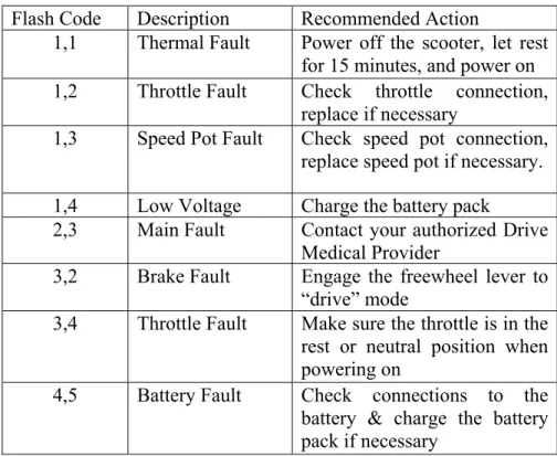
The Drive Scout 4 scooter consists of a wheel mobility chair that is light, easy to drive and has a troubleshooting process (Table 1.4). In this case, the problems are indicated through LEDs located in front of the steering wheel.
Table 1.4 Code Fault of the Drive Scout 4 (Manufacturing, 2017) Flash Code Description Recommended Action
1,1 Thermal Fault Power off the scooter, let rest for 15 minutes, and power on 1,2 Throttle Fault Check throttle connection,
replace if necessary
1,3 Speed Pot Fault Check speed pot connection, replace speed pot if necessary. 1,4 Low Voltage Charge the battery pack
2,3 Main Fault Contact your authorized Drive Medical Provider
3,2 Brake Fault Engage the freewheel lever to “drive” mode
3,4 Throttle Fault Make sure the throttle is in the rest or neutral position when powering on
4,5 Battery Fault Check connections to the battery & charge the battery pack if necessary
1.2.3 Merits
This Merits scooter is slightly bulkier than the other two, and its error indicator is a LED located onto the steering wheel. The number of flashes indicates the errors as shown in Table 1.5.
Table 1.5 Flash Code Error(Merits) Flash Code Description
1 Battery needs recharging 2 Battery voltage too low 3 Battery voltage too high 4 Current time limit out 5 Magnetic Brake fault 6 Not in neutral at power up 7 Speed pot error
8 Motor volts error 9 Other internal error
Among the flash codes, the first 3 are referring to the battery state. After studying the three scooters’ pride mobility was selected, then a literature review of power wireless systems for this type of battery will be presented.
Some of the mechanical problems that can be presented with these scooters are shown in Figure 1.5, As an example with the GoGo elite scooter (Pride), a bearing had to be changed after taking a slope of more than 45 degrees. Another issue presented with thee Scout4 (Drive), it was a peak current on the charger that caused the controller to get burnt. For the other scooter the merits of the S141 Pioneer after a week of use, the batteries must be changed.
Figure 1.5. Typical problems with mobility scooters
Wireless Power Systems Classification
For the last few decades, a huge interest in WPT has developed. This technology has been viewed as a viable alternative to reduce the need for wires.
The types of transmission can be divided into two categories: far field and near field. The first one is mainly designed for low-power applications with lower priority of transmission efficiency. This system is normally used with microwave or laser. The second one, the near-field transmission, is highly efficient and less radiofrequency is presented. The resonant coupling has become dominant in WPT as is shown in Figure 1.6.
Figure 1.6 WPT Classification(Jawad, 2017)
1.3.1 Near Field
Near-field wireless energy transfer can be conducted using wire coils with a short distance. Moreover, it can work with an operational frequency of around 10 kHz to several mega-Hertz. Near field is subdivided into the following categories.
Capacitive coupling: transferring energy between two electrodes that form a capacitance, where electric fields are created, and displacement current maintains the current stability. Resonant Inductive Coupling: there is normally a low coupling between the coils. Mostly on these systems, a large inductance voltage is primarily necessary. Consequently, a high current is generated, and greater losses are present in both coils, quantified by the Q factor. It is normal in order to compensate for the secondary leakage inductance; as a result, a capacitance is connected in parallel or in series with the coil. This kind of system is one of the most popular. A simple flowchart is shown in Figure 1.7.
Figure 1.7. WPT in resonance inductive (Longzhao Sun, 2018)
Inductive Coupling: In this case, a conductor with a current flowing generates a magnetic field, When the wire is wound into a coil, the magnetic field is concentrated. Basically, the magnetic field strength of a coil is defined by the flux density.
1.3.2 Far Field
With this technology, energy can be transferred over several kilometers. Microwave power transmission
The power transmission which consists of electric energy conversion to microwaves using a magnetron. On reception, microwave energy is converted to electrical energy using a rectifier and an antenna.
Laser Radiation:
Photonic energy is transferred from the transmitter to the receiver using a laser. This technology allows for a high energy concentration in long distances. The power can be transmitted without high-frequency interference. Besides, this energy can be transmitted via
free space or optical conductors. However, poor efficiency can be reached depending on the weather conditions. However, the transmitter and the receiver must have a line of sight contact. Near field is going to be used for the battery charger on the mobility scooter with a resonant coupling based on the descriptions that were mentioned in this chapter such as distances between the coils, frequency and coupling. In the next section, different topologies of resonant converters are going to be explained in order to choose the best topology for this project.
Wireless Power Standards
Nowadays there are two low power wireless power standards as illustrated in Figure 1.8. The Qi and the AirField. The wireless power consortium or Qi standard is characterized by the coupling between the two coils, the transmitter, and the receiver and the alignment between them. The most popular application is the phone charger. This standard uses band communication. In contrast, the AirFuel Alliance architecture is like Qi, but the coil structure is different. On the AirFuel, the coils are loosely coupled. Consequently, high leakage is presented.
Figure 1.8 WPT Standards (Cem Som, 2019) WPT Standards
AirFuel Alliance
Power: 1W-70W
Operating principle: resonance. Communications: Bluetooth low
energy
Wiresless power consortium
Power: 5W- 2.4Kw Operating principle:
Inductance, some resonance
Electromagnetic interference (EMI) /Electromagnetic Compatibility (EMC) for Wireless Power Transfer
Electromagnetic interference (EMI) and Electromagnetic Compatibility (EMC) protection is important in WPT systems and should be considered during the R&D process. Highly resonant power transfer systems based on AirFuel standards are subject to EMI regulation as any other power converter as well as other regulations.
The EMI propagation in a wireless power system is more difficult than traditional power circuits because classic techniques significantly impact the performance of the coil and tuning circuits. There are three standards that govern EMI:
• The radiated EMI limits;
• The internationally for industrial, scientific and medical (ISM) bands; • The non-ionizing human radio frequency exposure limits.
The biggest challenge for consumer wireless power products, based on the AirFuel standard, covers the frequency range of radiated emissions from 6 MHz to 1 GHz. The ISM band radiator standards limit the frequency bandwidth of radiated energy but essentially allow unlimited radiated power, with a few exceptions in the frequencies targeted for wireless power transfer. However, the limits for exposure to human radiofrequency (RF) adopted by the Federal communications commission (FCC), the institute of electrical and electronics engineers (IEEE), and the International Commission for Protection against Non-Ionizing Radiation (ICNIRP): based on specific absorption rate (SAR) become the power limiting factor for the wireless power transfer systems.
AirFuel-based wireless power transfer systems operate at 6.78 MHz which is an unlicensed ISM band frequency, with 13.56 MHz and 27.12 MHz as additional suitable ISM band frequencies, which can be used in special cases and power levels. Near Field Communications (NFC), popular in products such as RFID and card readers, which now include smartphones, use Citizen Band 13.56 MHz radio, licensed, and many radio-controlled devices use 27.12
MHz. These two frequencies are the 2nd and 4th harmonics of 6.78 MHz and some designers have suggested that since these frequencies are also ISM bands, the need to suppress EMI at these frequencies can be relaxed, thereby reducing the requirements for EMI filter design. This approach is not recommended because products, such as smartphones, already include NCF functionality, which can be damaged by the wireless power transfer system.
A radiated EMI system consists of five basic components: 1) an EMI source, 2) a transmission path 3) a radiator (antenna) 4) a receiver and 5) the radiated EMI standards that define the spectral limits of electromagnetic energy, as shown in Figure 1.9.
EMI filtering is not considered as a component of an EMI system, but rather as a means of limiting the propagation of energy in the system and the frequency range in order to minimize the electromagnetic emissions from the antenna. The receiver should not be confused with the receiver used for EMI testing, but rather any circuit (receiver) that can be corrupted by the radiated spectral energy. In addition, a far-field receiver, like the one used for EMI compliance testing, cannot distinguish whether the source is an H-field (di/dt), an H-field can inductively couple interference currents into neighboring conductions paths or an E field (dc/dt) is the measurement of interference voltage.(Cem Som, 2019).
Figure 1.9. General WPT architecture(Cem Som, 2019)
The EMI radiator in a traditional power electronic product can be a combination of circuit boards, cable harnesses, and ports. This is true for a wireless power product too, but the source
coil becomes the main radiator due to its size, construction, and function. For this reason, EMI radiators, owing to the balance of the wireless system, are not discussed as they are equivalent to traditional power electronic products, and classic solutions can be used for EMI compliance. The source coil is simply a large inductor with high impedance. Current in the coil is supplied by the amplifier which is enhanced by series-tuning the coil with a capacitor to yield low impedance. This current generates the H-field used for power transmission and thus radiates any spectral energy present in the current. All frequencies, except for the fundamental transmission frequency, are deemed unwanted as they can exceed the EMI limits imposed by the standards and must, therefore, be adequately attenuated from the current prior to entering the source coil.
Topologies of AC-DC Resonant Converters
Electrical resonance occurs in an AC circuit when the two reactances which are opposite and equal cancel each other for a determinate frequency, which is denominated as a resonance frequency. As an example of a resonance circuit, a capacitor and an inductor can be connected in series, when the resonance frequency indicates the real and imaginary impedances are equal but with opposite signs; consequently, the real part remains due to ESR (Equivalent Series Resistance).
Therefore, working with a WPT system in resonance allows the maximum power transfer of energy defined also by the distance between the coupled coils sharing the same magnetic path. Considering that the losses in the circuit are due to the parasitic resistances of the real components determined at the resonance frequency, this leads to the best performance that can be obtained by such a system.
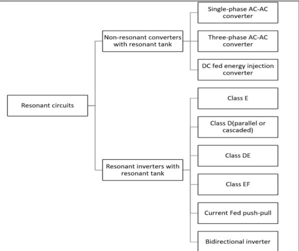
The WPT consists of a transmitter and a receiver. This AC input is rectified after the transfer coils which can be circular, rectangular, or of other kinds. The resonant circuits used in the industry are shown in Figure 1.10.
Figure 1.10 Classification of the resonant circuits used in the industry (Jiang, 2017)
Some characteristics of these resonant circuits can be listed as follows: the AC-DC converters help to use an AC power from the grid to DC power.
These topologies can be listed as:
● Single-phase AC-AC converters: can show free oscillation and energy injection control, as advantage DC-link (It is the DC voltage that is fed into the inverter and as the name implies, the two sources are linked together with a filter capacitor) and bulk energy storage can be zero;
● DC Fed Energy: low power level can be transfer. .
In spite of the fact that those 3 non-resonant converters described before upgrade the resonance frequency with low switching losses, they have high undulation currents in the resonant tank ( also called as a resonant circuit is an LC circuit consisting of an L inductor and a capacitor C), which are the consequences of the energy undulation (Jiang, 2017).
For most applications, the non-resonant converters are neither easy to control nor provide stable output. As a result, a resonant inverter with resonance tank is a better solution for near-field WPT system; some of which are:
● Class E: it is an LC tank without DC energy injection; in this topology, high efficiency at high frequency and high-power level is granted. In contrast, a low-power production is presented;
● Class D and DE: in the class D with full bridge a lower switching is given. Also, the combination of DE represents a low switching voltage with a high frequency operation; ● Class EF: On this topology, a switch drain voltage and output current can conduct a
better interference performance.
As a summary, on Table 1.6, a small comparison was made.
Table 1.6 Topologies with high resonant WPT (Cem Som, 2019).
On other topologies, The LC, LLC, and LCL are topologies that can help overcome a high efficiency in the WPT systems for mobility scooters.
Moreover, on the WPT systems with inductance coupling there are 4 main topologies: Serie-Serie (SS)-Serie-Serie Parallel (SP), Parallel Serie-Serie (PS), Parallel-Parallel (PP).
Figure 1.11 WPT Systems Topologies (Sheng-Yang, 2018)
The topology selection depends on the final applications of the system. However, the Serie-Serie topology is a well-known structure as the resonant capacitor value is not affected by the coupling coefficient of the coils, which means the system is neither going to be really affected by the distance between coils nor by the load charge.
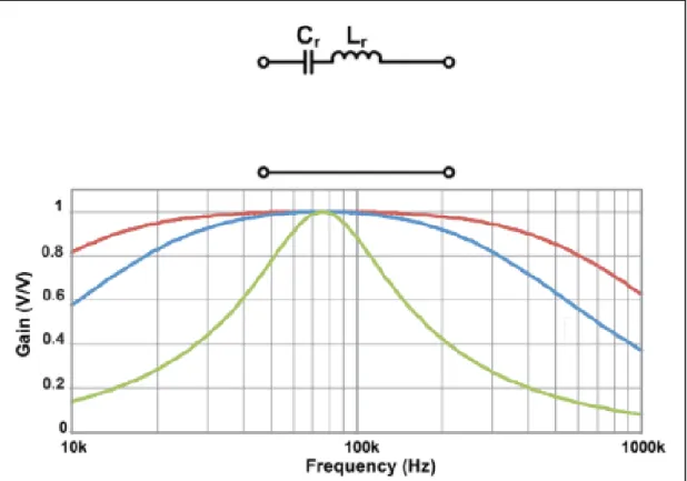
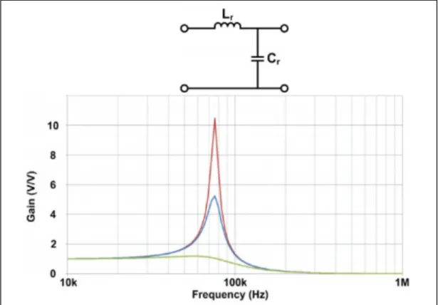
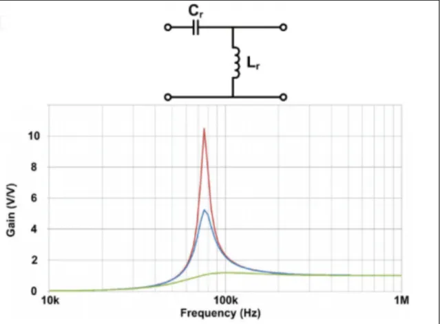
Series resonance has at least two resonant elements connected in series and cascaded between input and output (Figure 1.12). At the resonant frequency, the impedance of the resonant elements connected in series becomes zero. Therefore, the input-output gain is equal to one. Besides, the SR provides a lowering function of voltage as a buck converter. Parallel resonance is formed by at least one inductor and one capacitor as shown in Figure 1.13 and Figure 1.14. The gain voltage can be very high around the resonant frequency. The Notch resonance is formed either with an LC in parallel and placed in series, or with a LC in series and placed in parallel with the output load.
Figure 1.12. Gain curves vs frequency of a CL series resonant topology (W. Z. Li, H.; Deng, J.; Li, S.; Mi, C.C, 2016)
Figure 1.13. Gain curves vs frequency of an LC parallel resonant topology (W. Z. Li, H.; Deng, J.; Li, S.; Mi, C.C, 2016)
Figure 1.14. Gain values vs frequency of a CL parallel resonant topology (W. Z. Li, H.; Deng, J.; Li, S.; Mi, C.C, 2016)
The main advantage of resonant converters is their reduced switching loss via mechanisms known as zero current switching (ZCS) and switching at zero voltage (ZVS). The activation and / or deactivation transitions of the different semiconductor elements of the converter can occur at zero crossings of quasi-sinusoidal waveforms of the resonant converter. This eliminates some of the switching loss mechanisms. Consequently, the switching loss is reduced, and resonant converters can operate at switching frequencies higher than comparable PWM converters. Zero voltages switching can also eliminate some of the sources of electromagnetic interference generated by the converter.
In resonant converters, the power flow can be controlled by the switch to change the frequency of the rectangular voltage, its duty cycle (or both), and by special control schemes, such as phase shift control. An ideal switch is characterized by very high gain and extremely fast switching. Although users often ignore the intricacy of the switching operation, assuming this is not critical to the design overall, the fact is that a good understanding of the factors that affect switching can have a deep effect on system performance, especially frequency, and is therefore of vital interest to the user who needs to optimize its design.
Resonator Structure
Figure 1.15 Resonant structure geometries for WPT systems (Abou Houran, 2018) Figure 1.15 shows several research works related to resonator structure geometry such as Flat/Planar Coils, 3D Coil Geometry, Track/Rail and coils within cores and additional factors which are affected by or influence the geometry. The suitable application type is also given for each structure as well as some frequency ranges. Different studies have been investigated based on the shape of the resonator.
Geometries as flat/planar shaped coils can be defined as rectangular-shaped structure (W. Z. Li, H.; Deng, J.; Li, S.; Mi, C.C., 2018), octagonal Resonator (Park, 2016), or a double coil D (DD) (W. W. Zhang, J.C.; Abraham, A.M.; Mi, C.C., 2015). In addition, the defected ground structure (DGS) is presented in (Hekal, 2017). DGS means that a "fault" has been incorporated into the ground plan of a flat microwave circuit: this DGS technique is adopted to improve various parameters of a microwave circuit, such as low gain and narrow bandwidth.
Three-dimensional (3D) geometries are investigated, such as for instance, bowl-shaped transmitter coils (Campi, 2016), which are used for charging hearing aids, cylindrical coils (F. L. Zhang, J.; Mao, Z.; Sun, M., 2012), helix-loop resonators (Yang, 2014), and conical coils. In(Chabalko, 2014), the three-dimensional resonant cavity is presented, which offers a good way of charging multiple devices simultaneously.
Coils’ materials are discussed, for example, a receiver coil made of aluminum is used in (Song, 2014). In (Jeong, 2016), the authors proposed a helical-type coil made of superconductors in order to increase the quality factor of the coils. In (Kang, 2017), the authors applied an MCR WPT system (planar textile resonators or PTRs) to wearable consumer electronics by using flexible materials.
Coils with cores are given, such as dipole-type coils (M. K. Kim, H.; Kim, D.; Jeong, Y.; Park, H.H.; Ahn, S, A, 2015), which present a WPT prototype that is capable of transferring the power up to a 5 m distance. To charge vehicles, buses, trams, and trains, long-track transmitter and short-individual tracks are used (M. K. Kim, H.; Kim, D.; Jeong, Y.; Park, H.H.; Ahn, S, 2015). Moreover, E-core and U-core types are discussed (Wang, 2017).
In Electric Vehicle applications due to space limitations, some structures such as the helix, the omnidirectional, the cavity or the conical structure cannot be used, yet the resonators are designed in a spiral or flat coil shape. The advantages of these geometries are that they are printable and easy to implement at low cost. Furthermore, dynamic charging systems are used, which can be divided into two categories according to the track length. The first category is the long track transmitter, which can charge multiple EV at the same time. The long track transmitter system is simple partly due to the low number of components. One example of that kind of system is the Online Electric Vehicle (OLEV) with a maximum charging power up to 100 kW. The downside of this design is its low efficiency of 74%.
The second category is the short-individual transmitter with a length of about 1 m. These systems are arranged in an array to make a tracking lane and each transmitter has a compensation circuit, which can be excited based on the location of the receiver. The benefit of this structure is flexible, but its downside is that it requires many circuit components and converters making it more difficult to implement.
The first reason why the coils used for WPT systems are planar is that the profile area of the coils is small, which means it is easy to integrate with the other parts of the system. The other reason is that when the coils are wider than all the transmission systems, they can reach larger distances and the system becomes more tolerant of alignment errors between transmission and receiver coils. Interestingly, the most common material for the conduction coils is copper, which has excellent conductor thermal and electrical properties also in the WPT systems, this material has a good performance in high frequencies. When an AC current travels through the coil, the current through the coils is not uniform, which costs a reduction of the efficacy area on the conductor; on the inner section fewer current travels, and consequently, the electrical resistance is higher. One of the materials widely used nowadays is Litz wire, which is formed by an enamel copper fiber having the most similar impedance in all the copper threads. Some of those are shown in Figure 1.16.
Figure 1.16 Classification of Litz constructions types (technologies, 2018)
Wireless Power Transfer Coil Selection
For the selection of the coils, two main factors must be considered: the lower and the higher resonant frequency in the wireless power system. A classical inductance topology is shown in Figure 1.17.
Figure 1.17 Topology of Inductances in a WPT system (Cem Som, 2019)
In the series power transfer systems (Figure 1.17) tuning increases the current; as a result, the impedance is lower, on the other hand, the parallel tuning increases the voltage the impedance. During the design stage, the current and voltage requirements can be found following specific load conditions. Coupling factor and load power variations change the tuned resonance of the coils and this fact must be considered when the amplifier and the rectifier are designed so as to avoid the exchange of highly reactive power in the resonant circuit.
Application: 200 W WPT system with Data Transfer
The described application only allows for wireless transfer on or off. Many applications including the industrial and medical sectors require more control over the signals as well as the possibility to transfer data.
This type of transfer includes inductive coupling based on the magnetic flux between two coils. On the transmitter side, there is an oscillator, which works as an inverter feeding a resonant circuit constituted by the transmitter coil. On the receiver side, the system consists of the receiver coil and the rectifier, which generates DC current from high frequency AC input. The oscillator generates an alternating current from the input AC voltage, which then generates an alternating field in the transmitter coil. The energy is transmitted between the transmitter coil and the receiver coil, thanks to counter induction between the two coils according to Faraday’s law of induction, and it is then rectified and passed onto the load.
Figure 1.20 Current flow receiver through the 200W. WPT system Figure 1.19 Current flow transmitter through the 200W. WPT system
The stray flux is a direct outcome of larger distances between transmitting and receiving coils resulting in energy transmission decreases. This can be alleviated by resonant inductive coupling improving the range and the efficiency of the circuit. An LC series resonant circuit can be used, and the resonant frequencies of the oscillating circuit must be tuned. The very high stray inductance is almost completely compensated with capacitors in series with the wireless power transfer. The circuit is not self-oscillating, so the switching frequency is determined by the oscillator and is tuned to the resonant frequency of the series resonant circuit. Advantages of this concept:
• Large power scale (from 10 W to several 10 kW);
• Good EMC thanks to the sinusoidal aspect of the resonant circuit and rectifier;
• Efficiency over 90% due to zero voltage MOSFET turn-on switching;
• Easy adaptability for many voltages/current uses;
• The output voltage can be higher or lower than the input voltage by adjusting the switching frequency.
Control strategies of the LLC converter topology
The application of control theory and feedback can eliminate steady-state errors, moderate system sensitivity to parameter changes and disturbances, and modify the gain or phase of the system over the desired frequency range. Moreover, to achieve output voltage regulation any converter must be coupled with a feedback control system.
Figure 1.21. Control types in an LLC converter 1.9.1 Variable Frequency
For the output voltage regulation, the LLC resonant converter varies its switching frequency to manipulate the voltage gain observed at the output. This type of control requires a gate drive signal that has a constant duty cycle but varying the frequency.
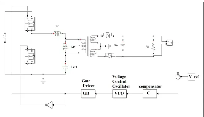
Voltage controlled oscillation control: to implement variable frequency control, an actuator that can produce a variable frequency signal is required and can be realized by a voltage-controlled oscillator (VCO). The VCO is defined by an electronic circuit designed to produce an oscillation frequency based on the control voltage and can be implemented on the gates of the primary side of the topology as is shown in Figure 1.22. Besides, the frequency of the gates is varied in contrast to line and load. Changing the impedance of the resonant tank wide-ranging the converter gain change. Complex design in the magnetic components is necessary (F. Musavi, 2013),(S. W. Kang, 2014),(S. Kang, 2016)
LLC Control Variable frequency Voltage-controlled oscillation control. VCO Self-sustained Oscillation control (SSOC) Constant frequency operations Asymmetrical PWM control. Pulse density modulation control (PDM) Secondary-side control
Figure 1.22 Diagram of a voltage-controlled oscillation for an LLC converter
Self-Sustained Oscillation Control (SSOC): is used to achieve voltage regulation and high frequency for a wide range of load currents. This type of control allows a minimum power factor angle and consequently a smaller primary current to reduce conduction losses, leading to a better working efficiency. The control diagram is shown in Figure 1.23.(P. Kowstubha, 2014)
Figure 1.23 23Diagram of Self-Sustained Oscillation Control for an LLC converter The main objective of the SSOC controller is to control the switching frequency to simultaneously guarantee both output-voltage regulation and ZVS of the converter. To achieve this operation, the SSOC is composed of two control loops: an inner loop and an outer loop. The inner loop adjusts the phase shift or control angle between the resonant current and inverter output voltage to guarantee ZVS under any operating condition. The outer control loop adjusts output voltage according to the reference value, and the control voltage is compared to the sawtooth that is synchronized, with zero-crossing the resonant current to adjust the required phase shift for ZVS. (Jain, 2007a, 2007b; L. Sahaya Senthamil, 2012).
1.9.2 Constant Frequency Operations
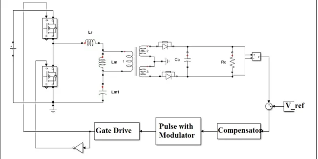
This type of control is a fixed frequency and modifies the duty cycle of the pulses to regulate the output voltage. Asymmetrical PWM control: it can achieve the zero-voltage switching (ZVS) turn-on the power switches of the primary side and to reduce the circulating current loss. Besides, in the turn-off cycle, the ZCS can be achieved by the output diodes. Moreover, for controlling the on and off time in the switches, a constant frequency is delimited. This control improves the magnetic elements. The APWM has shown in Figure 1.24.
Figure 1.24 Diagram of Asymmetrical PWM control for an LLC converter
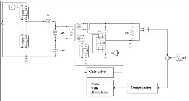
Generally, APWM control schemes have the stress with unbalance of the output components and the reverse recovery problem on the secondary side of the transformer. In contrast, the decrease in the duty cycle increases harmonics. (B. Kim, 2012; Nakaoka, 2009; W. Cha, 2016) Pulse Density Modulation Control (PDM): this power control is provided by deleting some of the on-pulses without changing the turn-on the duration of the switch. The output power of the converter decreases as the number of the deleted pulses increases. The PDM is also known as a burst mode control. The output power is controlled; however, the voltage is not the same design as the Asymmetrical PWM, but the PWM block is digital. This control method has the characteristics of voltage stress and high conduction loss. (H. Mizutani, 2013; Oncu, 2017) Secondary-side control: As the name indicates the control is in the secondary side of the transformer; a synchronous rectifier (SR) is used to control the time on of the MOSFET as shown in Figure 1.25. Increasing a filter output selection has led to keeping the ripple low at the output. (H. Wu, 2015; J. Liao, 2011; W. Feng, 2010).(P. Kowstubha, 2014).
Figure 1.25 Diagram of a modulator pulse control inthe secondary side of the LLC converter The review of the literature shows that the efficient control method is asymmetrical PWM control giving a fixed frequency and load despite giving the option of a simple filter selection. In this chapter, the main uses of micro-mobility vehicles with power wireless systems are listed. Besides, based on market research, the common brands are pride, drive, and merits with the best performance and low price. Moreover, the WPT systems are detailed as far-field and near field. In this research, the near field is going to be used because it is highly efficient, and less radiofrequency is presented for battery charger purposes.
The geometry-shape as a spiral coil planar with Litz material is nowadays used in the WPT systems. The LLC converter is selected because it is a topology that has high efficiency in energy transfer for WPT systems in the near field.
CHAPTER 2
ANALYSIS OF THE LLC CIRCUIT TOPOLOGY
LLC Circuit Topology
The LLC type of circuit topology has the following characteristics:
• Easy design for the inverter working as a voltage source in the primary side; • Output voltage regulation on the whole power output range;
• Three free design steps: voltage gain range between the input and the output, work frequencies interval, quality factor;
• The inductor series in the resonant tank mitigates the peak current on the inverter and on the resonant tank;
• LLCs are generally used in distributed power systems and WPT; this converter has the advantage of zero voltage switching (ZVS) overall operation mode. Besides it can reduce the power losses during the switching and low EMI (electromagnetic Interference) emission as well.
2.1.1 Fundamental characteristics of the LLC resonant converter
The main circuit components and layout of the LLC are shown in Figure 2.1. The bridge inverter switches are controlled with 50% duty cycle. The frequency control is variable to regulate both the output voltage and current. The LLC topology can be implemented as well in half or full-bridge configuration (Martinelli, 2001).
Figure 2.1 LLC Converter topology
As shown in Figure 2.1, V1 is the DC input voltage and 𝑉 is the output voltage of the inverter. The switching bridge can be half-bridge as shown in Equation (2.1) or a full-bridge topology as shown in Equation (2.2). Having the topology of the switching bridge the DC bus voltage V1 is calculated by:
𝑉 𝑉 /2 (half-bridge) (2.1)
𝑉 𝑉 full − bridge (2.2)
The configuration of the resonant tank consists of the Cr that is well known as resonant capacitance, the inductances 𝐿 (resonant inductance) and 𝐿 (transformer’s magnetizing inductance.
Operation of a Full Bridge Resonance Converter
A typical converter full-bridge converter topology has three main parts. Such as switching bridge, LLC tank, transformer, and rectifier. The switching bridge power switches as Q1, Q2, Q3, and Q4 are generally MOSFETs.
2.2.1 Waveforms in the resonant converter
A sinusoidal current flow is circulating in the resonant circuit, voltage and current signals are phased shifted because the switching frequency of the full bridge is higher than the resonant frequency of the series resonant tuned circuit. There are two operation points, the inductive operation point which the phase shift presents Zero Voltage Switching (ZVS) operation possibly giving the highest efficiency. On the other hand, a capacitive operation point is when the current precedes the voltage, the converter no longer works in ZVS mode, but in Zero Current Switching (ZCS) mode. The ZCS operation leads to higher losses because of the current commutates into the body diodes of the MOSFETs resulting in possible destruction of the MOSFETs.
2.2.2 Data transmission between transmitter and receiver
Two series resonant circuits also enable transmission of data between the transmitter and receiver side and vice versa by modulating the alternating field between the coils.
2.2.3 Loosely coupled system Transmitter coil tuning
The transmitter coil can be represented by an inductor. It is typically measured using a Vector Network Analyzer (VNA). Before turning the transmitter coil, it should be placed in its base mode defined as being in its final product state, and without any device or foreign metal object present. Although a shunt capacitor can be connected to the coil that increases the impedance,
this is not typically done as it tends to increase the coil sensitivity to load changes and foreign metal objects.
A series capacitor is used to reduce the impedance. In some instances, a designer may terminate the tuning either inductively or capacitively depending on the use case adjustment requirements.
Receiver Coil Tuning
The receiver coil is like the transmitter coil and can also be represented by an inductor. Before tuning the receiver coil, it should also be placed in its base model without any source or foreign metal object present.
A shunt capacitor can be connected to the coil that increases the impedance. The higher impedance of shunt tuning is helpful to increase the output voltage of the coil but should be used sparingly as it can increase the loading impact and/or excessive undesirable imaginary impedance shifting on the transmitter coil. A series capacitor is used to reduce the impedance. 2.2.4 Closely Coupled System
The wireless power transfer energy system compliance with the EMC limits is non-trivial. The challenge is that the transmitter and receiver coils behave like a transformer with a poor coupling factor and a very large air gap. This leads to a very high stray electromagnetic field in the vicinity of the coils. EMC measurements have shown that broadband interference can occur in the spectrum of the fundamental wave through to the signal. If the level of interference measured is kept below the limit with some margin, it may be assumed that the limits of the interference field strength are also maintained.
Magnetic field can inductively couple interference currents into neighboring conduction paths. Usually, a greater separation or a ferrite absorber sheet, such as a flexible sintered ferrite sheet is helpful to minimize the interferences
First Harmonic Approximation
The analysis of the resonant converters’ family is complex. The characteristic of reactive elements and switching in the vicinity of resonance frequencies introduces non-linearities that are not represented in an average model of the converter. In the article (Huang, 2011) authors present several methodologies to linearize or obtain a transfer equation of several shapes. Among them, the First Harmonic Approach (FHA) will be presented. One of the most useful methodologies this technique is based on assuming that the current flowing through the circuit is of sinusoidal type. In the LLC tank only circulates the fundamental component of the signal. Since the frequency of switching is always around the series resonance frequency, the fundamental component of the current will be the one that is considered for the calculus of the power transfer in the circuit. In this case, the high-frequency harmonics can be neglected. If the switching frequency is moved away from the resonant frequency, more harmonic components appear that will produce less accuracy. The design process in order to define the ratings of the components is followed by:
1. Representing the square input voltage and current with the fundamental component, ignoring the other harmonic components;
2. Ignoring the effect of the output capacitor, the rectifier, and the dispersion inductance in the secondary of the transformer;
3. Referencing the variables from secondary to primary;
4. Representing the square voltage in the secondary of the transformer referenced to the primary with the fundamental component, ignoring the other components.
Figure 2.2. A typical configuration of the resonant converter
Figure 2.3. Simplified converter circuit squared showing Vos and Vsq. No linear non-sinusoidal circuit
Figure 2.4. Equivalent Circuit of the converter. Linear sinusoidal circuit
Where the circuits elements shown in Figure 2.3, 2.4, 2.5, and 2.6 are defined by: 𝑉1, is the DC voltage;
𝑉 is the quadratic output of the full-bridge inverter; 𝑉 , 1 is the fundamental component of the 𝑉 ; 𝑉 is the voltage on the load;
𝑉 is the simplified output voltage;
𝑉 is the fundamental component of the 𝑉 voltage; 𝐼 is the current on the load R;
𝐼 is the fundamental component of 𝐼 ; 𝐶 is the resonance capacitor in the LLC Tank; 𝐿 is the resonant Inductor in the LLC tank; 𝐿 is the transformer’s magnetizing inductance; 𝑁 is the number of turns in the primary coil 𝑁 is the number of turns in the secondary coil 𝑓 is the switching frequency.
𝑓 is the series resonant frequency. 𝑅′ is the 𝑅Load from the primary side;
𝑅 is the equivalent 𝑅 Load reference of the primary with the FHA simplification; 𝑄 , 𝑄 , 𝑄 , 𝑄 Mosfet on the full bridge.
Impedance Calculation
The resonant tank gain can be calculated from the equivalent resonant circuit as shown in Figure 2.5:
Figure 2.5. Resonant Tank equivalent circuit non-sinusoidal circuit Which the transfer function is (detailed are shows in appendix A):
𝐾 𝑄, 𝑚, 𝐹 𝑉 𝑠 𝑉 𝑠 𝐹 𝑚 − 1 𝑚 ∗ 𝐹 − 1 𝐹𝑥 . 𝐹 − 1 . 𝑚 − 1 . 𝑄 (2.3) Where: 𝑄 / Quality Factor;
𝑅 ∗ ∗ 𝑅, Reflected load resistance; 𝐹 , Normalized switching frequency; 𝑓
. , Resonant frequency;
Figure 2.6 Resonant Tank equivalent circuit linear sinusoidal circuit 𝑍 𝑠 = 𝑠𝐿 + 1 𝑠𝐶 + 𝑠𝐿 𝑅 𝑠𝐿 + 𝑅 = 𝑠 𝐶 𝐿 𝐿 + 𝑠 𝐶 𝑅 𝐿 + 𝐿 + 𝑠𝐿 + 𝑅 𝑠 𝐶 𝐿 + 𝑠𝐶 𝑅 (2.4)
After having the impedance of the LLC resonant tank, the two resonant frequencies can be calculated by (2.5) and (2.6). Where 𝑓 is the total resonant frequency and 𝑓 is the Serie resonant frequency. 𝑓 = 1 2𝜋 𝐶 (𝐿 + 𝐿 ) (2.5) 𝑓 = 1 2𝜋 𝐶 𝐿 (2.6)
2.4.1 Theory of resonant tank operation
The resonant circuit’s selective property is defined by the amount of current to be circulated and transferred to the load independence of the resonance circuits impedance (assuming variable frequency control). A series resonance with LC tank converter has the resonance frequency as was shown in Equation (2.5) and (2.6) where 𝑓 𝑎𝑛𝑑 𝑓 were defined as total
resonance and series resonance frequencies. Moreover, the resonant converter 𝑓 is defined as the resonant frequency depending on the load when the current and voltage input has a zero phase (Lind, 2013).
On the LLC circuit, 𝑓 value is depending on the load so the frequency could be 𝑓 ≤ 𝑓 ≤ 𝑓 , where; no load 𝑓 = 𝑓 . As the load increases, 𝑓 moves towards 𝑓 . At a load short circuit 𝑓 = 𝑓 .
According to this description, there are three operation regions as shown in Figure 2.7.
Figure 2.7. LLC Regions (Appendix A, Solving equation 2.5 varying 𝑄 ). As shown in Figure. 2.7, on Region 1, 𝑓 ≥ 𝑓 the tank impedance is inductive. In Region 2 also, 𝑓 ≥ 𝑓 𝑎𝑛𝑑 𝑓 ≤ 𝑓 , the impedance is inductive. In Region 3, 𝑓 ≤ 𝑓 , the impedance is capacitive and if 𝑓 = 𝑓 the impedance in the resonant tank is resistive. The switching frequency 𝑓 improved the impedance of the resonant tank. Regions 1 and 2 are defined by zero voltage switching, in this case, the technique of soft switching can be applied, and this
area is known as an inductive. On the other hand, region 3 is capacitive and is well-known as zero current switchings.
In Figure 2.8, the operation zones are described and are going to be explained thereafter: Operation at Resonance (at 𝑓 )
In this mode, the resonant tank is working at the series resonance frequency, it is the optimal operating point giving the best efficiency of the system for f0=fr . When Q1 turns off, the resonant current decrease until the value of magnetizing current and there is no more power transferred. Slight delay for the Q2 switch allows the circuit to achieve ZVS on the primary side and soft commutation on the secondary side.
Operation Below Resonance (𝑓 < 𝑓 )
The ZVS can still be obtained by the primary side of this operation region, also soft commutation mode in the rectifier in the secondary side can be obtained, but if the resonance frequency becomes too low it generates switching losses and several associated issues.
Operation Above Resonance (𝑓 > 𝑓 )
At this stage, a small circulating current is presented on the primary side, reducing current losses. On the secondary side, the diodes are not in soft commutation but the ZVS can still be present on the primary side. This method can cause an increase in the frequency under light load conditions.
Figure 2.8. LLC Operation (Huang, 2011)
To sum up, the best performance for the resonant tank can be achieved in the vicinity area, which consists of a loose designation between 𝑀 _ , 𝑀 _ , 𝐹 _ , 𝐹_ as shown in
Figure 2.9.
Transfer Function
The LLC resonant converter regulates the output voltage by varying the switching frequency of semiconductors, which has an immediate influence on circuit impedance. With this action, the impedance of the resonant tank varies causing variation in the output voltage. A mathematical method is described in order to calculated the relation between the output voltage and switching frequency.
To analyze the stability of the system a Bode diagram was made. Where the magnitude and phase response are displayed. The phase plot is usually in degrees (deg) and the magnitude is in decibels (dB) as shown in Figure 2.10.
Figure 2.10. Bode diagram of the LLC Tank impedance (𝐿 = 200𝜇𝐻, 𝐿 = 58𝜇𝐻, 𝐶 = 43 𝑛𝐹)