Analysis of postural stability of the human body during the
execution of standing industrial hand tasks
by
Fabrice LATOUR
THESIS PRESENTED TO ÉCOLE DE TECHNOLOGIE SUPÉRIEURE
IN PARTIAL FULFILLMENT FOR A MASTER'S DEGREE WITH
THESIS IN HEALTHCARE TECHNOLOGY ENGINEERING
M.A.Sc.
MONTREAL, OCTOBER 7, 2020
ÉCOLE DE TECHNOLOGIE SUPÉRIEURE
UNIVERSITÉ DU QUÉBEC
© Copyright reserved
It is forbidden to reproduce, save, or share the content of this document either in whole or in parts. The reader who wishes to print or save this document on any media must first get the permission of the author.
PRESENTATION OF THE BOARD OF EXAMINERS
THIS THESIS HAS BEEN EVALUATED BY THE FOLLOWING BOARD OF EXAMINERS
Mr. Rachid Aissaoui, Thesis Supervisor
Department of Systems Engineering, École de technologie supérieure
Ms. Nicola Hagemeister, Thesis Co-supervisor
Department of Systems Engineering, École de technologie supérieure
Mr. Mustapha Ouhimmou, President of the Board of Examiners Department of Systems Engineering, École de technologie supérieure
Mr. Carlos Vázquez, Member of the jury
Department of Software and Information Technology Engineering, École de technologie supérieure
THIS THESIS WAS PRESENTED AND DEFENDED
IN THE PRESENCE OF A BOARD OF EXAMINERS AND PUBLIC ON SEPTEMBER 30, 2020
ACKNOWLEDGMENTS
To Mamie Pauline, Lynda, Marie-France & Catherine
These last two years have been filled with ups and downs. But like a roller coaster, when the whole process comes to an end and you finally get a second to catch your breath, you realize it was worth it. The process of completing a Master's degree was much more than just an educational one, it was also learning about myself, what I'm able to accomplish, and how to balance uncontrollable situations. In life, just like with this thesis, when everything seems to be going sideways, composure, determination, and not derailing off course helped me ensure that all ended well. Although the unthinkable events of 2020 impacted the course and the outcome of this thesis, the learning experience became even more valuable.
Unfortunately, I wasn't able to conduct experimental trials on all my planned participants. At first, I was frustrated by the turn of events, but my two directors, Rachid and Nicola reassured me that my project was not a failure and provided me guidance that I had sufficient material to complete the project. This whole learning process would not have been possible without them and I am forever grateful that they have given me this opportunity of completing this thrilling project. They have challenged me on many occasions, gave me constructive feedback, and acknowledged when good work was accomplished. Thank you Rachid and Nicola for this professional and personal enrichment experience.
I would also like to thank Julie Charland and the whole team at Dassault Systèmes for their help and support during this project.
I thank my father who has supported me through this journey by giving me his advice from his own doctoral dissertation experience. I also thank my father and mother in law who were extremely generous with their time when it came to guiding me and allowing me to fabricate most of the experimental test bench in their garage. My dear friends, I thank you for supporting me throughout these years and understanding my absence on occasion.
It's hard to think that at first, I didn't want to continue my education after high school and that I wanted to become a heavy truck mechanic. This is why I would like to dedicate this master's degree to the four most important women in my life.
Mamie Pauline my grandmother, who has always been there for me with generous amounts of meals, always has a reassuring hug and taught me that when you smile, others will smile back in your presence. Lynda my mother, always had faith that I could succeed whatever I put my mind to. You and Michel supported me throughout my studies and always made sure that I had what I needed. You taught me so much about life, to be generous with others, and my knowledge of how to become autodidactic, qualities that I am forever grateful to have. Marie-France, my caring sister. You taught me to be rigorous and meticulous as paying attention to detail counts, but above all to live, laugh, and have exceptional food, because life is all about enjoying the little things, just like a Hershey's chipits. I am grateful to have had your guidance during my childhood and to have you as a friend for life today. At last, Catherine my loving fiancé, without who this thesis would not have been possible. Countless moments of proofreading my work, your patience during those infinite times of me asking you questions regarding the phrasing of sentences. I am so grateful to have your encouragement, support, and trust in me. Now that both of our Masters are accomplished, it's time to focus on our life dreams.
Although going back on this ride, as a researcher, might seem tempting, I have decided not to return on the same ride, but instead try a new one.
"Tuition is very valuable, but you know what's invaluable? Intuition."
Analyse de la stabilité posturale du corps humain lors d'exécution de tâches industrielles debout avec les mains
Fabrice LATOUR
RÉSUMÉ
Introduction: Le positionnement des pieds a un impact significatif sur le contrôle de la
stabilité du corps humain lors de la réalisation d'une tâche industrielle. Dans les modèles de simulation de la posture humaine actuels (DHM: Digital Human Model), l'utilisation de stratégies de pas pour générer des postures stables repose sur des modèles simplistes, qui localisent généralement le centre de masse (COM) du DHM à mi-distance entre le contact des pieds ou limitent seulement la projection d'un point nommé ZMP (Zero Moment Point) dans le polygone de sustentation nommé couramment BOS (Base of Support). Les données expérimentales assurant la coordination des mouvements humains pendant des tâches industrielles, qui peuvent être utilisées pour simuler et valider ces modèles DHM, sont rares.
Objectif: L'objectif de cette étude est de développer un banc d'essai expérimental
représentant des conditions industrielles et de réaliser des expériences pour fournir à ces modèles DHM des paramètres de stabilité posturale.
Méthodologie: Un sujet pilote a effectué quatre conditions de travail debout à une main,
c'est-à-dire: atteindre une cible, pousser et tirer une poignée, ainsi qu'utiliser un tournevis. Chaque condition fut réalisée dans deux positions différentes de cibles. Un obstacle transversal a été utilisé pour une des positions afin d'imposer des contraintes spatiales. La cinématique 3D de cinquante marqueurs réfléchissants, apposés sur des repères anatomiques, avec trois marqueurs auxiliaires sur le tournevis a été acquise à 200 Hz avec un système de capture de mouvement (VICON). Les forces et moments de réaction au sol sous chaque pied et à la cible ont été mesurés simultanément par trois plateformes de force (AMTI) à 1000 Hz. Les paramètres de stabilité posturale évalués pour cette étude étaient la longueur de support, qui est une variation de la longueur de pas, et la position du ZMP par rapport au BOS.
Résultats: Les expériences ont montré que les exigences de la tâche varient le placement et
l'orientation des pieds lorsqu'un obstacle est présent ou non, ce qui était conséquent pour tous les essais avec l'obstacle transversal, où la jambe controlatérale se déplaçait vers l'arrière. La moyenne de la longueur de support semblait plus petite pour les essais avec l'obstacle transversalement, ce qui indique que l'atteinte de la cible aurait pu être préférée à la stabilité.
Conclusion: La taille de l'échantillon est limitée ce qui restreint les conclusions. Les travaux
futurs prévoient réaliser le protocole expérimental complet sur un échantillon de sujet plus grand afin de développer un modèle de régression plus précis permettant de prédire la longueur de support selon le ZMP et son orientation selon la cible et les exigences à la main.
Analysis of postural stability of the human body during the execution of standing industrial hand tasks
Fabrice LATOUR
ABSTRACT
Introduction: Foot positioning has a significant impact on human body stability control
when completing a manufacturing task. In current Digital Human Models (DHM), the use of stepping strategies to generate stable postures relies on simplistic models, which generally locate the DHM center of mass (COM) at half distance between feet contact or limit the zero moment point (ZMP) projection within the base of support (BOS). Experimental data providing human movement coordination during manufacturing tasks, which can be used to simulate and validate these DHM models, are very scarce.
Objective: The objective of this study is to develop an experimental test bench representing
industrial conditions and to carry out experiments to provide these DHM models with parameters of postural stability.
Material and Methods: A pilot subject performed four different one-handed standing
working conditions namely: reaching a target, pushing and pulling a handle, as well as using a screwdriver. Each condition was performed in two different target positions. A transverse obstacle was used to impose spatial constraints for one of the target positions. The 3D kinematics of fifty reflective markers affixed on the anatomic human body with three additional markers on the screwdriver was recorded at 200 Hz using a motion capture system (VICON). Ground reaction forces and moments beneath each foot and at the targets was measured by three force plates (AMTI) simultaneously at 1000 Hz. The assessed postural stability parameters in this study were the support length which is a variation of the step length, and the ZMP position with respect to the BOS.
Results: Experiments showed that task requirements vary the position and orientation of feet
placement when an obstacle is present or not, which was consistent over all trials of moving the contralateral leg backward when the transverse obstacle was present. The mean support length magnitude appeared smaller for the handle location with a transverse offset which indicates hand-target reach might have been favored over stability.
Conclusion: It is noted that the sample size is limited, hence the conclusions remain partial.
In future works, it is intended to carry out the presented experimental protocol on a larger population size to develop a more precise regression model able of predicting the support length with respect to the ZMP position and its orientation about the target and the hand load direction requirements.
TABLE OF CONTENTS Page CHAPTER 1 INTRODUCTION ...21 1.1 Context ...21 1.2 Problem statement ...23 1.3 Objectives ...26 1.4 Research questions ...26 1.5 Overview ...27
CHAPTER 2 LITERATURE REVIEW ...29
2.1 Human stability control overview ...31
2.1.1 Description of postural strategies ... 31
2.1.2 Foot placement prediction models ... 37
2.1.3 Definition of the Zero Moment Point ... 40
2.2 Experimental human data capture systems ...44
2.2.1 Force evaluation for industrial tasks using hand tools ... 44
2.2.2 Experimental test bench designs ... 47
2.3 Conclusion ...50
CHAPTER 3 METHODOLOGY ...53
3.1 Industrial task posture evaluation ...53
3.1.1 Grouping of postures ... 55
3.1.2 Posture strategies classifications ... 57
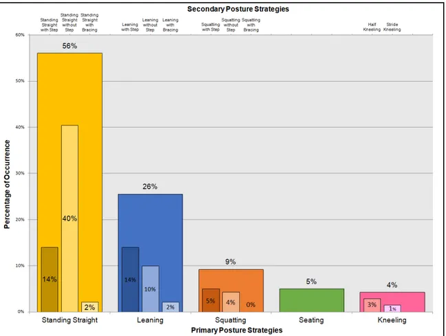
3.1.3 Posture strategies occurrences ... 58
3.1.4 Conclusion ... 61
3.2 The conception of an experimental test bench ...62
3.2.1 Requirements ... 62 3.2.1.1 Attributes... 62 3.2.1.2 Constraints ... 63 3.2.1.3 Good to have ... 63 3.2.2 Design ... 64 3.3 Case study ...70 3.3.1 Experimental methodology ... 70 3.3.1.1 Setup ... 70
3.3.1.2 Data collection equipment ... 71
3.3.1.3 Test tasks, locations, and conditions ... 74
3.3.1.4 Experimental protocol ... 78
3.3.2 Data collection protocol ... 83
3.3.2.1 Pilot subject ... 85
3.3.3 Data preparation ... 86
3.3.3.1 Evaluated parameters ... 88
CHAPTER 4 RESULTS & ANALYSIS ...93
4.1 Data verification & validation ...93
4.2 Results from experiments ...100
4.3 ZMP projection ...102 4.3.1 Results ... 102 4.3.2 Analysis ... 106 4.4 Feet adjustments...108 4.4.1 Results ... 108 4.4.2 Analysis ... 110
4.5 Postural stability control ...111
4.5.1 Results ... 111
4.5.2 Analysis ... 113
4.6 Limitations ...114
CONCLUSION & RECOMMENDATIONS ...115
APPENDIX I LITERATURE REVIEW SUMMARY TABLES ...119
APPENDIX II INDUSTRIAL TASK EVALUATION ...125
LIST OF REFERENCES ...139
LIST OF TABLES
Page
Table 2.1 Definition of Net COP equation variables ... 32
Table 2.2 Definition of ZMP equation variables ... 43
Table 3.1 Automotive companies & Assembly lines assessed ... 53
Table 3.2 Task assessment examples legend ... 54
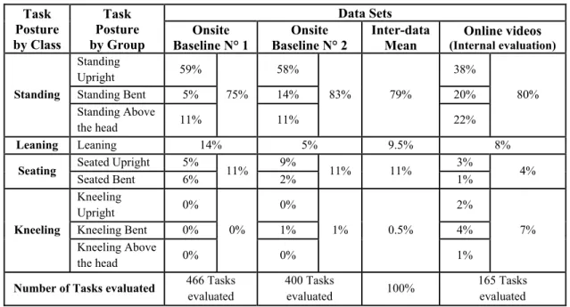
Table 3.3 Comparison of task assessments for three data sets in the automotive industry ... 56
Table 3.4 Primary Posture Strategies Definitions ... 57
Table 3.5 Secondary Posture Strategies Definitions... 57
Table 3.6 Test location lexicon ... 75
Table 3.7 Full experimental protocol overview ... 77
Table 3.8 Body landmarks lexicon ... 81
Table 3.9 Pilot subject data collection protocol test conditions and number of trials analyzed ... 83
Table 3.10 Pilot subject characteristics ... 85
Table 3.11 Center of mass calculation points ... 88
Table 4.1 Visual repeatability representation task high centered ... 93
Table 4.2 Summary of feet positioning and parameters projection ... 99
Table 4.3 Mean normalized (and standard deviations) D2 ratio, support length magnitude and lead foot occurrence across trials ... 103
Table 4.4 Mean (and standard deviations) lead foot-target distance and Support length-target orientation by condition ... 108
Table 4.5 Mean (and standard deviations) of the total postural sway by condition ... 112
LIST OF FIGURES
Page
Figure 2.1 The reference planes and axis representation ... 29
Figure 2.2 Subregion based stability criterion ... 33
Figure 2.3 Zero moment point representation with and without external loads when standing ... 41
Figure 2.4 Zero moment point representation with external loads when leaning ... 42
Figure 2.5 Industrial hand task with a tool ... 44
Figure 2.6 Capture system with adapter design ... 46
Figure 3.1 Task assessment examples ... 54
Figure 3.2 Distribution by grouping of postures ... 55
Figure 3.3 Distribution of Occurrences grouped by Primary Posture Strategies ... 58
Figure 3.4 Distribution of Secondary Posture Strategies in terms of Occurrence classified by Primary Posture Strategies ... 59
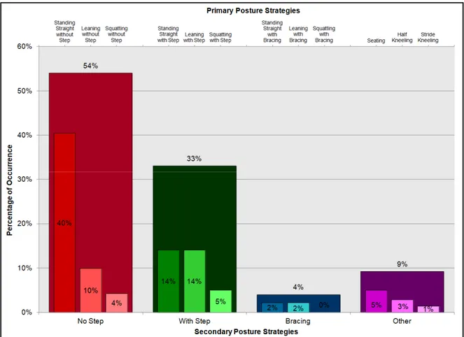
Figure 3.5 Distribution of Primary Posture Strategies in terms of Occurrence classified by Secondary Posture Strategies ... 60
Figure 3.6 Summary of postural evaluation tasks ... 61
Figure 3.7 Experimental test bench schematic diagram ... 64
Figure 3.8 Experimental test bench design ... 65
Figure 3.9 Screwdriver capture interface ... 66
Figure 3.10 Alternative tool interfaces ... 66
Figure 3.11 Pushing and Pulling handle capture interface... 67
Figure 3.12 Installed experimental test bench ... 68
Figure 3.13 Task requiring a transverse obstacle ... 69
Figure 3.15 Experimental setup ... 71
Figure 3.16 AMTI MC3A load cell ... 71
Figure 3.17 ATMI Side-By-Side Treadmill ... 72
Figure 3.18 VICON MX T20-S camera ... 73
Figure 3.19 Markers used with a tool ... 73
Figure 3.20 Designed test tasks ... 74
Figure 3.21 Tool shape effect comparison ... 76
Figure 3.22 Applied hand force monitor (Fz) ... 79
Figure 3.23 Anatomical landmarks for markers ... 80
Figure 3.24 Verification of gloves with markers ... 82
Figure 3.25 Hand marker gloves ... 82
Figure 3.26 Passive reflective marker affixed on the pilot subject ... 85
Figure 3.27 Gap filling ... 86
Figure 3.28 Three phases of a trial ... 87
Figure 3.29 Data modeling representation ... 89
Figure 3.30 ML and MR points, support length, and local coordinate system definition during quiet standing ... 90
Figure 3.31 Lead foot-target distance and support length-target orientation definition ... 91
Figure 4.1 Repeatability over 5 trials (Pushing a Centered High task) ... 94
Figure 4.2 NetCOP, COPL, and COPR in the anterior-posterior direction (Quiet side-by-side standing) ... 95
Figure 4.3 NetCOP, COPC, and COPV in the anterior-posterior direction (Quiet side-by-side standing) ... 95
Figure 4.4 NetCOP, COPC, and COPV in the transverse direction (Quiet side-by-side standing) ... 96
Figure 4.5 COG and NetCOP fluctuations in the anterior-posterior direction (Quiet side-by-side standing) ... 97 Figure 4.6 Comparison between the COG and the net COP anterior-posterior
distance from the ankle joint ... 98 Figure 4.7 Quiet side-by-side standing and pushing trial feet positioning
projection ... 99 Figure 4.8 COG and net COP correlation distribution ... 101 Figure 4.9 Processed trial parameters (XY plane projection) for a pushing
centered trial ... 102 Figure 4.10 Scatter plot of Support length magnitude with respect to the ZMP D2
ratio from the root foot grouped by conditions ... 103 Figure 4.11 Scatter plot of Support length magnitude with respect to the ZMP D2
ratio from the root foot grouped by handle location. Single-factor regression fitted model displayed with confidence and prediction intervals ... 104 Figure 4.12 Plot of residuals and limits with a confidence interval of 95% ... 105 Figure 4.13 ZMP projection in yellow and COG projection blue on the support
length between ML and MR. Mean normalized (and standard deviations) D2 ratio, support length magnitude, and lead foot
occurrence across trials. Reference quiet standing trial support length of 250.73 mm ... 109 Figure 4.14 Mean ZMP in yellow and mean COG in blue over the 5-second
LIST OF ABBREVIATIONS AND ACRONYMS
BOS Base of Support
COG Center of Gravity
COP Center of Pressure
COM Center of Mass
CRCHUM Centre de Recherche du Centre Hospitalier de l'Université de Montréal
DHM Digital Human Model
DOF Degree of Freedom
ETS École de Technologie Supérieure
FSR Functional Stability Region
HRF Hand Reaction Forces
LIO Laboratoire de recherche en imagerie et orthopédie
MOCAP Motion Capture
SPE Smart Posture Engine
RSME Root Squared Mean Error
CHAPTER 1
INTRODUCTION
1.1 Context
The use of digital simulators to evaluate complex and precise phenomenon is preferred by research centers as well as by industries since they allow the analysis of multiple scenarios faster and at a lower cost, compared to full-scale physical models. Specific three-dimensional digital human models (DHM) have been developed in Computer-Aided Design programs to integrate human body representations into simulated environments. These DHMs allow for ergonomic assessment and appraisal of interactions with the environment before developing optimized work stations or manufacturing products (Chaffin, 2008; Scataglini & Paul, 2019).
At the moment there is a large variety of anthropometrical and biomechanical DHMs used for diverse purposes. JACK (Siemens, 2020), SIA & TEO (Charland, 2019; Dassault Systèmes, 2020), and SANTOSTM (Abdel-Malek et al., 2007; Santos Human inc, 2020) are
commercially available DHMs that can be used for general ergonomic assessment as well as for accurate visual and physical dimension rendering of interactions between the humanoid manikin and the modeled environment. The AnyBody Modeling SystemTM (AnyBody
Technology, 2020) allows detailed human body structure calculations in relation to the simulated environment. Other models such a SAMMIE (Marshall et al., 2010) and RAMSIS (Bubb et al., 2006; Human Solutions, 2020) have been developed to evaluate fit, reach, and line of sight for specific body positions, mostly during seated postures. IMMA developed by Hanson et al. (2012, 2014), HUMOSIM developed by Reed, Faraway, Chaffin, and Martin (2006) and the Smart Posture Engine (SPE) developed at the LIO laboratory (Lemieux, Barré, Aissaoui & Hagemeister, 2020) are all research projects aiming at developing an autonomous biomechanical digital human model allowing collision-free predictions of simulated kinematics and dynamics, mostly for industrial tasks. This thesis is motivated by the SPE technology to enhance the stability control of the DHMs final postures.
A common aspect DHMs strive to improve is their autonomy to position the human manikin in a biomechanically plausible posture under specific task conditions. Currently, few models allow for semi-autonomous placement of the manikin in the simulated environment requiring manual interactions by the user to refine the final simulated postures (Berlin & Adams, 2017; Chaffin, 2008; Scataglini & Paul, 2019). Different computational methods are used by DHMs to position the manikin in the environment and ensure it is adopting a stable posture. Some models use inverse kinematics mathematical models to position the manikin's joints and segments (Chaffin, 2008). Some of these models have integrated optimization-based methods that generate plausible postures based on objective functions and constraints to predict the manikin's position when facing a defined situation (Berlin & Adams, 2017). Other models use experimental kinematic and dynamic data-bases to generate postures (Scataglini & Paul, 2019). Lastly, manual manipulations of individual joints can always be performed by the user but it is a basic and tedious method to position the humanoid manikin.
The full automation of digital human models would be a significant advancement in this field as a fully independent manikin would no longer require user inputs. For models simulating standing tasks, stability criteria are very important to ensure the generation of biomechanically plausible postures. A considerable element when evaluating the stability of the human body is foot placement with respect to the task position and load requirements (Holbein & Redfern, 1997; Winter, Patla & Frank, 1990). As specified in the works of Winter et al. (1990), during a static standing stance it is mandatory to maintain the body Center of Gravity (COG), which is the vertical projection of the Center of Mass (COM), within the Base of Support (BOS) to ensure postural stability. The BOS is an area defined by the convex hull of the feet contact points with the support plane. Moreover, Holbein and Redfern (1997) defined a functional stability region (FSR) with limits representing 60% of the Base of Support (BOS) during standing tasks while handling loads. This smaller region represents an area where small compensatory body adjustments can be made to maintain a stable posture. Postural stability adjustment strategies are classified into two predominant categories: ankle strategy and hip strategy (Horak & Nashner, 1986). Horak and Nashner (1986) defined the ankle strategy as being the restoration of stability by displacing the Center
of Mass around the ankle joints. These same researchers defined the hip strategy as being the COM movement primarily around the hips by varying moments about the knee and hip joints. When the center of mass exits the base of support and its velocity is directed away from the BOS, the ankle or hip strategies are insufficient to restore stability equilibrium, therefore stepping is prevalently required (Pai & Patton, 1997). Because the stepping strategy allows the enlargement of the base of support, it is usually preferred when accomplishing tasks that require external loads or a distant reach, as the COM will tend to move towards the functional stability region limits hence, requiring a step (Pai et al., 1998).
1.2 Problem statement
In industrial conditions, the use of stepping to maintain a stable posture is frequent as workers will often reach or apply forces when accomplishing tasks (Wagner, Reed & Chaffin, 2010). Classical digital human models that utilize stepping behaviors to generate stable postures rely on simplistic models, which generally locate the DHMs center of mass at half distance between the feet contact positions (Badler, Phillips & Webber, 1993). Predictive stepping models use experimentally collected data and calculations to predict data-based feet placement. These models rely on regression equations with the task characteristics as the inputs to position the manikin's feet (Faraway, 2003; Reed & Wagner, 2007; Wagner et al., 2010). They can predict transition stepping, but pose some challenges when simulating more complex asymmetrical handling or tool manipulation tasks with task parameters different from the experimentally collected data. An alternative computed force-controlled posture model by Seitz, Recluta, Zimmermann, and Wirsching (2005) generates plausible postures that are natural representations, but that is not necessarily accurate with respect to experimental trials. Instead, it is favored to predict global whole body posture by maximizing produced joint torques while reducing joint strain. Optimization-based stepping models compute the feet position along with the posture generation through minimizing an objective function (e.g., joint torques) (Howard, Yang & Ozsoy, 2014; Marler, Knake & Johnson, 2011). The main stability criterion for these models is accomplished by limiting the calculated zero moment point (ZMP) projection to stay inside the BOS. This is a basic
formulation that respects minimal stability requirements. The ZMP represents a virtual point where the total tilting moments, generated from gravitational and external forces, applied to the manikin are zero (Vukobratović & Borovac, 2004). Although this method generates stepping according to external requirements, it has not yet been validated with suitable experimental data to verify if the feet placement is accurate. The more recent stability-based stepping model proposed, which uses the position of the ZMP with respect to the functional stability region to quantify stability, was developed as part of an improvement to the SPE (Zeighami, Lemieux, Charland, Hagemeister & Aissaoui, 2019). The SPE is a posture prediction model used to generate biomechanically plausible final postures of a DHM given the simulated environment and the task information (Lemieux, Barré, Hagemeister & Aissaoui, 2017, 2020). The main stability difference in this model is that the ZMP and the feet placement are controlled more precisely by using the functional stability region, a smaller region than the BOS situated between feet contact, allowing the manikin to recover maximum stability depending on the required target reach, height, and loads. However, no experimental data has yet been produced to validate this concept.
In the literature, the large majority of studies that have proposed feet positioning models studied general two-handed push-pull tasks (Hoffman, Reed & Chaffin, 2007a, 2010; Marler et al., 2011; Wagner et al., 2010), which is not representative of the observations found in the industrial field (Baril-Gingras & Lortie, 1995). The study conducted in industrial settings by Baril-Gingras and Lortie (1995) allowed the identification of different postural strategies used during material handling tasks. Of the 944 handling tasks that were observed one-handed tasks and two-one-handed asymmetrical tasks represented respectively 55.4% and 35.6% of the handlings, which accounted for more than 90% of all evaluated handlings. This indicates that one-handed and out of sagittal plane tasks should be preferred when studying industrial tasks. In this same study, horizontal pushing and pulling (48.2%) was seen almost twice as often as vertical lifting and lowering (26.6%), where tasks accomplished with horizontal and transverse components were the most frequent. When reviewing the literature, accurate stepping behavior models derived from specific industrial task experiments providing human movement coordination are very scarce. No feet prediction model assessed
tasks involving hand tools. Also, no study evaluated the effects of a transverse obstacle imposing spatial constraints and requiring subjects to execute tasks out of the sagittal plane without prescribing specific feet placement, which has been underlined by Wilkinson, Pinder, and Grieve (1995) to require further investigation. Imposing specific feet position for out of sagittal plane tasks shows a strong indication that foot placement and posture constraints may have an important effect on force exertion capability (Haslegrave, Tracy & Corlett, 1997; Warwick, Novak, Schultz & Berkson, 1980; Wilkinson et al., 1995). Granata and Bennett (2005) studied the effects of split and side-by-side stances on stability during pushing tasks, where stability was found to be significantly influenced by feet placement. For digital human models to become fully autonomous, the stepping prediction models need to be enhanced, in order to take into account the out of sagittal plane tasks.
Although bracing and other postural strategies exist in the industrial field, this study focuses on maintaining stability through the stepping strategy, while executing tasks in different hand conditions, by limiting the use of other postural strategies. In this study, the subject is free to position their feet as wanted in order to adopt a preferred posture. Moreover, the use of a transverse obstacle requires the subject to execute the conditions without aligning themselves with the direction of the applied hand force. The use of a tool while completing the same tasks allows the evaluation of its influence on feet placement when compared to typical push and pull conditions. Because no previous study evaluated a transverse obstacle, the scaling of the target position was based on other scaled parameters found in the literature (Granata & Bennett, 2005; Haslegrave et al., 1997; Jones, Reed & Chaffin, 2013).
1.3 Objectives
The previous DHMs that utilize the zero moment point to maintain stability only partially control its position to stay within the base of support, which represents minimal stability requirements. The primary objective of this thesis is to develop an experimental test bench that will allow the evaluation of the required parameters to assess the zero moment point and human postural stability, such as the support length with respect to the functional stability region and the base of support. The second objective is to carry out experiments with the intent of developing a regression model that will estimate the required support length with respect to the ZMP position.
1.4 Research questions
Derived from the aforementioned objectives, three research questions have been defined.
• What tasks should experimental test subjects perform to have an appropriate representation of what is observed in the industrial sector?
• How to conceive an experimental test bench that will acquire accurate and repeatable experimental data to evaluate postural stability?
• Can a regression model potentially estimate the support length from the ZMP position?
The hypothesis resides on the fact that by developing an experimental test bench capable of evaluating postural stability parameters and the ZMP position, appropriate data will be acquired enabling the development of an accurate regression model. Furthermore, it is hypothesized in support of the regression model that during either centered tasks or tasks with a transverse obstacle, the contralateral and ipsilateral legs move respectively to expand the BOS in the direction of ZMP displacement in order to maximize the stability threshold.
1.5 Overview
The subsequent sections will present content that answers the previously described research questions and ultimately achieves the main objectives.
Chapter 2 provides a detailed review of related works to assess previous studies that have investigated DHM postural stability by feet positioning and ZMP position, and experimental test bench evaluation.
Chapter 3 discusses the utilized methodology. The first part provides information on defining frequently encountered task postures in the industrial sector. The second part covers the development of an experimental test bench that will capture parameters of postural stability. The third and final part presents the experiments carried out on subjects with a focus to measure foot positioning and external forces.
Chapter 4 is dedicated to presenting the interpreted results acquired by the test bench and motion capture system and will lay out an analysis of these results.
Chapter 5 develops on discussion and recommendations for future works regarding postural stability evaluation when stepping.
CHAPTER 2
LITERATURE REVIEW
In this chapter, a review of previous works will be conducted to assess the following topics: Human stability conservation and experimental human data capture systems.
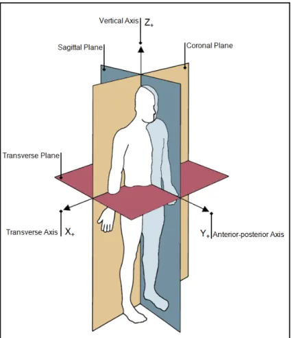
In order to facilitate the evaluation of the diversified studies retrieved from the literature, a common lexicon will be used throughout the rest of this thesis. Figure 2.1 illustrates the three reference planes and axis for a standard anatomical human position based on the works of Vaughan, Davis, and O'Connor (1999).
• The Base of Support (mm2): Region defined by the points of contact between the feet
with the ground;
• Stepping: Feet positioned in a staggered or split stance type;
• No stepping: Feet positioned in a side-by-side stance type;
• Contralateral: Opposite foot of working hand;
• Ipsilateral: Same side foot of working hand;
• Step length (mm): Distance between both heels in the anterior-posterior axis
(Vaughan et al., 1999);
• Stance (mm): Distance between feet in a side-by-side position;
• Support length (mm): The support length is the line passing through the projected
points ML and MR, which are virtual points obtained from the intersection of the projected longitudinal axes (straight lines connecting the Phalanx Distal II and the heel) of the feet with the balance line projected on the ground (Badler et al., 1993). The balance line is a line passing through the mean center of gravity (COG) during quiet standing and its direction is found by connecting the left and right mid malleolus (See Figure 3.30);
• D2 ratio (mm): Ratio from the root foot (trailing leg) of the square projection of the
2.1 Human stability control overview
This section will consider three notions of human stability parameters. First, the different postural strategies will be treated. Secondly, different foot placement prediction models that exist will be reviewed. Finally, the zero moment point will be described in detail.
2.1.1 Description of postural strategies
Postural strategies are used to maintain the human body stable when standing, as they allow repositioning of the Center of Mass (COM) in a position where the whole body will remain stable (Horak & Nashner, 1986). Table-A I-1 in APPENDIX I presents these studies.
As stated by Horak and Nashner (1986), the use of the ankle and the hip strategies allow for easier control of the body's stability when standing without requiring continuous variation in muscle structures. When standing straight without any perturbations the human body will continuously compensate for small variations, which generates a natural sway. This natural sway can be measured by assessing the COM or by evaluating the net center of pressure (net COP) derived from individual feet center of pressure. Winter, Prince, Stergiou, and Powell (1993) evaluated the effects of the natural sway on the computed net COP using the following equations (2.1), (2.2), and (2.3). Results from ten subjects displayed in the anterior-posterior direction that the left and right foot COP displacements were perceived by the net COP, but not in the transverse direction. Instead, loading and unloading of the vertical reaction forces were predominantly seen in the transverse direction to maintain balance.
𝐍𝐞𝐭𝐂𝐎𝐏 𝐭 = 𝐂𝐎𝐏𝐋(𝐭) ×𝐑 𝐑𝐕𝐋(𝐭) 𝐕𝐋(𝐭) + 𝐑𝐕𝐑(𝐭)+ 𝐂𝐎𝐏𝐑(𝐭) × 𝐑𝐕𝐑(𝐭) 𝐑𝐕𝐋(𝐭) + 𝐑𝐕𝐑(𝐭) (2.1) 𝐂𝐎𝐏𝐂(𝐭) = 𝐂𝐎𝐏𝐋(𝐭) + 𝐂𝐎𝐏𝐑(𝐭) 𝟐 (2.2) 𝐂𝐎𝐏𝐕(𝐭) = 𝐍𝐞𝐭𝐂𝐎𝐏(𝐭) − 𝐂𝐎𝐏𝐂(𝐭) (2.3)
The variables used in these equations are defined in Table 2.1.
Table 2.1 Definition of Net COP equation variables
𝐍𝐞𝐭𝐂𝐎𝐏(𝐭) → Net COP.
t → Time variable (s).
𝐂𝐎𝐏𝐋(𝐭)
𝐂𝐎𝐏𝐑(𝐭)
→ Magnitude of Left foot COP. → Magnitude of Right foot COP.
(resultant of anterior-posterior & transverse components)
𝐑𝐕𝐋(𝐭)
𝐑𝐕𝐑(𝐭)
→ Vertical reaction forces of Left foot. → Vertical reaction forces of Right foot. 𝐂𝐎𝐏𝐂(𝐭) → Effect of average Left and Right foot COP.
𝐂𝐎𝐏𝐕(𝐭) → Vertical reaction forces loading/unloading contribution.
Holbein and Redfern (1997) first detailed the area where small postural strategies can be used to maintain a stable posture as the functional stability region (FSR). These researchers evaluated the COG and reported that the limits of the FSR represent 53.7% in the anterior direction, 61.5% in the posterior direction, and 62.2% in both transversal directions from the center of the Base of Support (BOS) to its limits. However, the FSR was underestimated as the transversal limit of the BOS was defined with respect to the 5th metatarsal whereas the
COG displacement was calculated according to the anterior-posterior center of the BOS which is behind the 5th metatarsal, a location where the foot is slightly narrower.
During a subsequent study on this matter by Holbein-Jenny, McDermott, Shaw, and Demchak (2007) a more detailed six-sided functional stability region was established from adults aged between 23 and 73. The experimental evaluations on fifty-two subjects determined a similar anterior limit at 57.8% of the BOS limits with two additional diagonal measurements at 45 ° left and 45 ° right of 66.9% and 69% respectively. As for the other limits, posterior was evaluated at 54.7%, left transverse at 67%, and right transverse at 65.8% of the BOS limits. The FSR is significantly dependent on age. In fact, when evaluating the same data set but for the younger age groups between 20 and 39 years old, the FSR enlarges in all directions. Anterior becomes 69.2%, posterior 57.6%, 45 ° left 74.7%, 45 ° right 76.8%, transverse left 76.5% and transverse right 73.9%.
Pai, et al. (1998) evaluated the instant where stepping occurs and defined a stepping threshold. According to the results obtained from forty-nine young, old non-faller, and old faller subjects, stepping was imminent for all three perturbation conditions once the COM was within 10% of the BOS limits. Because generating a step widens the base of support, this allows the COM to return inside the BOS and therefore recover to a stable posture.
An investigation of the different subregions found inside the base of support was conducted by Popovic et al. (2000) to propose a stability criterion for quiet standing based on the location of the COP within the BOS. Three elliptical subregions normalized to the foot length and one residual region were defined as part of this study. These regions are represented in the following Figure 2.2.
The high preference region represents the zone where the COP is situated during almost the entirety of quiet standing. The low preference region is the remaining zone where the COP is situated during quiet standing. The third area is the undesirable region where the adoption of postural strategies is necessary to remain stable. The residual zone is considered the unstable region where stepping is mandatory to maintain balance. The foot length ratio parameters of each region are respectively 0.16, 0.43 & 0.59 for Dy and 0.07, 0.57 & 0.97 for Dx with all
centers being in the sagittal plane and at 47% of the foot length from the heel position in the anterior-posterior axis.
Differently to what was seen in the previous studies, Stapley, Pozzo, Grishin, and Papaxanthis (2000) used both the estimated center of mass and the center of pressure to evaluate human stability when executing forward reaching. The stabilization of the COM was mainly completed by axial synergies (e.g., movement of the head and shoulders opposite from the hip displacement), limiting the required COM displacement for subjects to remain stable. As the reaching distance increased, the posterior hip displacement increased ensuring the COM stays within the BOS. The COP displacement was characterized by a three-phase trajectory sequence. The COP started by moving slightly backward as the COM moved forward. Then, it changed direction until it passed the COM. Once the terminal position achieved, the COP remained in the anterior limit of the BOS. These results are however limited to the fact that feet position was restricted. Permitting feet movement would have enabled the expansion of the BOS which in terms could have limited the required axial synergies to maintain postural control.
As mentioned earlier, stepping is important to maintain a stable posture when performing tasks that require the manipulation of loads, the application of external forces, or reaching as this strategy allows the enlargement of the base of support. In the material handling research of Wagner et al. (2010) split stance (i.e., staggered) during task pickup represented nearly 71% of all the 462 experimental trials that were evaluated. Split stance compared to side-by-side stance has a major impact on the task that can be accomplished. Larger amounts of
forces can be applied and objects do not need to be brought as close to the body when the feet are staggered.
The study by Baril-Gingras and Lortie (1995) conducted in industrial settings allowed the identification of different postural strategies used during material handling tasks. A total of 944 handling tasks were observed with on average three to four efforts per handling, representing a set of 3217 identified efforts. Several considerable results were extracted through a thirty-six variable grid covering effort type, effort direction, foot position, whole-body behavior, the position of the hands, and much more. First of all, horizontal pushing and pulling (48.2%) happens almost twice as more often than vertical lifting and lowering (26.6%). Secondly, one-handed tasks (55.4%) and two-handed asymmetrical tasks (35.6%) accounted for more than 90% of all evaluated handlings which indicates that two-handed symmetrical tasks are undoubtedly not frequent. In regards to posture, 25.4% of efforts had a form of moderate forward flexion, and 11.7% utilized the squatting strategy which was defined by knee flexion. A form of stepping was observed in 34.6% of all the handlings that required upper limb movement or exertion and a minimum of two steps, as other forms of stepping proved to not be reproducible. Lastly, 76.7% of the efforts required the exertion to have a horizontal component and 45.7% of efforts were accomplished in a single plane. Also, half of all efforts were executed towards or away from the body in the transverse axis (1582/3217, 49.2%). Despite the limited space imposed by the work environment, the predominance of asymmetry and executing tasks out of the sagittal plane were not dependent on spatial constraints of the feet, as workers could position themselves how they desired. Only 9.2% of the efforts started with the subjects' feet in line with the axis of the movement appending the fact that asymmetrical positioning is pivotal.
Wilkinson et al. (1995) evaluated posture variations for one-handed force exertion on subjects standing at a predominantly side-by-side foot position, as feet were required to be equidistant from the centerline of the target. Asymmetrical pushing and pulling were investigated, but the researchers stated that additional work needs to be conducted in order to explain the postural behaviors that support transverse force production. Forces out of the
sagittal plane require specific body strategies to ensure the maintenance of a stable posture. Moments of up to 50 Nm were seen produced in the horizontal plane about the foot center of pressure point by subjects during the study of Wilkinson et al. (1995), most likely explaining that foot base torque generation is required to overcome out of plane forces. This study was limited by the COP being calculated from the handle reaction force vector and the extreme posture assumptions made when calculating the COG from anthropometric tables, which generated positioning errors of 38 mm for the COP and 39 mm for the COG.
During the study by Haslegrave et al. (1997), one-handed force exertion was evaluated in unnatural positions requiring out of sagittal plane forces to be applied. Experiments were conducted in six directions (pull, push, upwards, downwards, across body & sideways) under four task positions (standing at shoulder height, standing twisted, standing overhead, and lying supine on floor overhead). Each task imposed a position for the right foot and had specific conditions as to subject orientation. The reference for the maximal voluntary effort was assessed from pushing a handle positioned at shoulder height while standing at maximal reach. Imposing this posture allowed the isolation of muscular effort by limiting the use of body weight to increase applied force. Results showed that task orientation and reach distance have an important impact on force exertion capability with some instances being reduced by 50%.
No study has yet explored the use of a transverse obstacle to assess the positioning of the feet. Few studies evaluated the effect of rotation for tasks out of the sagittal plane (Haslegrave et al., 1997; Warwick et al., 1980; Wilkinson et al., 1995). However, during these studies, instead of using obstacles, subjects were positioned with their feet constrained at a specific position. Moreover, comparing out of sagittal plane task results from these three studies show a strong indication that foot placement and posture constraints may have an important effect on force exertion capability.
2.1.2 Foot placement prediction models
Over recent years, digital human models have started to integrate more accurate foot prediction models that help to calculate and to simulate the manikins in biomechanically plausible postures. Table-A I-2 presented in APPENDIX I summarizes the five different foot placement prediction models that have been retrieved through the literature review. Some models require experimentally collected data and regression equations to generate data-based feet placement. Other models require body constraints and inverse dynamic computations before conducting an optimization process (e.g., minimizing joint torques) to generate plausible feet placement. At last, there are inverse kinematics models, that use mathematical models following biomechanical constraints and stability functions to calculate ideal static feet position.
The model proposed by Wagner, Reed, and Chaffin (2006) is based on experimental data from load manipulation transfer tasks. The predicted stepping is determined from a foot behavior matrix and regression equations arising from the task and subject descriptions, and a behavioral classification data set. Once the stepping behavior is selected, the foot placements are constrained and an inverse kinematics analysis is applied to calculate the lower limb positions. Although results from this model generate plausible postures and transition stepping, they are limited to the experimentally collected foot trajectory data, which poses some challenges when simulating more complex material handling or tool manipulation tasks (Reed & Wagner, 2007).
In terms of postures generated by optimization prediction, three models were retrieved. The main stability criteria for the models of Marler et al. (2011) and Howard et al. (2014) is accomplished by limiting the calculated zero moment point projection to staying inside a trapezoid BOS. This is a basic formulation that respects minimal stability requirements. The presented models have the same objective of minimizing an objective function (e.g., joint torques). Constraints are similar with the purpose of limiting the joint angles, the reach distance between the hand and the target as well as ensuring the stability of the manikin.
During the study of Marler et al. (2011), feet position were not fixed and after the optimization process, final feet location was calculated to simulate the most realistic posture while respecting the ZMP stability criteria. The model calculates the reach distance constraints based on anthropometric data. This specifies a boundary area on the support surfaces where hand(s) and the feet placement must remain within. These features allow the manikin to adopt a split stance position in a natural, but not necessarily accurate posture.
The model used by Howard et al. (2014) has not yet been validated with experimental data. As part of their study, results were only visually validated. Although feet were not constrained to a specific position, results don't seem to trigger any considerate stepping. Nonetheless, the model was able to predict feet position and orientation with respect to the supporting hand loads. The manikin stability for this study was such that it adhered to the minimal stability requirements. This signifies no postural adjustments, such as lowering the COG or displacing feet was accomplished to ensure the manikin was adopting the most stable posture possible. Furthermore, during the simulations researchers didn't apply any external loads at the task hand which would consequently affect the simulated posture as the ZMP calculation utilizes these forces.
In the model presented by Delfs, Bohlin, Hanson, Högberg, and Carlson (2013), which is also an optimization-based model, the objective function is defined as a comfort function. This function corresponds to joint angles, joint torques, reach distance, and interference with the environment as well as a stability parameter. Feet were free to slide on the support surface and rotate about the vertical axis, but the remaining three DOF were fixed. The balance was determined from the static equilibrium of the model, where stability was determined from the gradient of a potential function, derived from all the forces and moments, being greater than zero for all displacements. By giving more importance to the required stability in the comfort function, the manikin adopts a more stable posture (wider stance or longer step length). The model seems to produce adequate stepping but has not been validated to verify if the postures are accurate representations of what workers would do
or only generated plausible postures. The plausibility nature is due to variations in ways individuals complete tasks and prospective situations that don't physically exist to be evaluated by humans.
The stepping prediction model proposed by Zeighami et al. (2019), which is used as part of the SPE model, also uses the ZMP to generate biomechanically plausible final postures. The SPE uses an inverse kinematics solver with selective filtering and prioritized constraints similar to Baerlocher (2001) while avoiding the collision with the environment. The main stability difference in this model is that the ZMP and the feet placement are controlled more precisely with respect to the functional stability region, a smaller region than the BOS situated between feet contact. This allows the manikin to be simulated adopting the most stable posture possible depending on the required target reach, height, and loads. If the ZMP doesn't exit the functional stability region during the task, no stepping is triggered. Nonetheless, no experimental data has yet been produced to validate this concept.
2.1.3 Definition of the Zero Moment Point
The zero moment point (ZMP) is a concept that is widely used in the biped locomotion field. The position of this virtual point is mostly exploited for dynamic state of stability feedback in humanoid robots.
Using this concept for stability purposes is relevant as it considers the effect of external loads applied to the studied body. As stated by Winter et al. (1990), during a static posture a person is considered stable when the projected position of the center of gravity (COG) is situated inside the base of support. However, when external loads are present, this statement is no longer valid. Therefore, the ZMP can be defined as a point where the total tiling moments, generated from gravitational and external forces perceived by a studied body are zero (Vukobratović & Borovac, 2004).
As mentioned in the works of Vukobratović and Borovac (2004) if the position of the ZMP is situated within the base of support, the body is considered dynamically stable. When the ZMP approaches the edge of the BOS, the counterbalance moments created by the feet reaction forces with the support surface decrease while the tilting moments generated by gravity and external forces increase. Consequently, the body could easily fall if any perturbation would arise.
Although it is possible for the center of gravity and the zero moment point to be outside of the base of support while the studied body remains stable (Pai & Patton, 1997) in this thesis only static standing postures will be studied. Figure 2.3 and Figure 2.4 illustrate the concept of stability based on the ZMP position for four different scenarios.
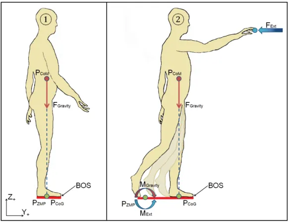
Figure 2.3 Zero moment point representation with and without external loads when standing
In the first scenario shown in Figure 2.3, no external forces are present, hence the position of the ZMP (PZMP) and the position of the COG (PCoG) coincide, which results in no tilting
moments and enabling the control of the COG inside the base of support. The ankle strategy and hip strategy are generally used to maintain a stable posture (Horak & Nashner, 1986).
In the second scenario presented in Figure 2.3, an external force (FExt) is applied. As the
external force increases, the tilting moments around the position of the ZMP increase as well. If the base of support is not large enough to compensate for the effects of the external moments, stepping is imminent to correct this unbalance trend. Thus, a foot will displace until the base of support has grown sufficiently to recover to a stable posture.
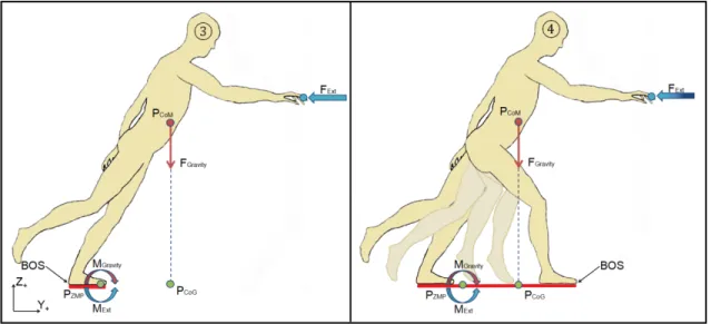
Figure 2.4 Zero moment point representation with external loads when leaning
The third scenario illustrated in Figure 2.4, shows a situation where a leaning body assessment proves to be stable. However, this is not an ideal or pragmatic representation of posture stability as if the external force (FExt) disappears, the body would immediately fall.
The fourth scenario shown in Figure 2.4 presents a valid representation of what should occur when adopting a leaning posture. The feet should displace to enlarge the base of support and ensure that the position of the ZMP (PZMP) and COG (PCoG) remain within the BOS as the
external force increases.
For this thesis, the ZMP calculation will be accomplished with equation (2.4) which are derived from the equations presented in the works of Howard et al. (2014). As for the position of the Z component, it will be considered as being on the support surface, in other words on the ground, therefore 𝐙𝐌𝐏𝐙= 𝟎.
𝐙𝐌𝐏𝐗=(𝐌 𝐛𝐲 + 𝐟𝐛𝐱(𝐢) × 𝐙(𝐢) − 𝐟𝐛𝐳(𝐢) × 𝐗(𝐢) + 𝐦𝐠 × 𝐗𝐂𝐨𝐆) (𝐦𝐠 − 𝐟𝐛𝐳) 𝐙𝐌𝐏𝐘= (−𝐌𝐛𝐱 + 𝐟𝐛𝐲(𝐢) × 𝐙(𝐢) − 𝐟𝐛𝐳(𝐢) × 𝐘(𝐢) + 𝐦𝐠 × 𝐘𝐂𝐨𝐆) (𝐦𝐠 − 𝐟𝐛𝐳) 𝐙𝐌𝐏𝐙= 𝟎 (2.4)
Considering that for this thesis subjects will only complete one-handed tasks it is possible to simplify the previous equation and obtain equation (2.5).
𝐙𝐌𝐏𝐗=(𝐌 𝐛𝐲 + 𝐟𝐛𝐱 × 𝐙 − 𝐟𝐛𝐳 × 𝐗 + 𝐦𝐠 × 𝐗𝐂𝐨𝐆) (𝐦𝐠 − 𝐟𝐛𝐳) 𝐙𝐌𝐏𝐘=(−𝐌 𝐛𝐱 + 𝐟𝐛𝐲 × 𝐙 − 𝐟𝐛𝐳 × 𝐘 + 𝐦𝐠 × 𝐘𝐂𝐨𝐆) (𝐦𝐠 − 𝐟𝐛𝐳) 𝐙𝐌𝐏𝐙= 𝟎 (2.5)
The variables used in this equation are defined as presented in Table 2.2.
Table 2.2 Definition of ZMP equation variables
𝐙𝐌𝐏𝐗 𝐙𝐌𝐏𝐘 𝐙𝐌𝐏𝐙 Coordinate of the ZMP: → (X component) → (Y component) → (Z component, equal to 0) 𝐌𝐛𝐱 𝐌𝐛𝐲
Magnitude of reaction external moments applied on the body: → (X component) → (Y component) 𝐟𝐛𝐱 𝐟𝐛𝐲 𝐟𝐛𝐳
Magnitude of reaction external force applied to the working hand: → (X component) → (Y component) → (Z component) 𝐗 𝐘 𝐙
Coordinates of the center of the load cell:
→ (X component) → (Y component) → (Z component)
𝐦𝐠 → Force applied to the body due to gravity.
𝐗𝐂𝐨𝐆
𝐘𝐂𝐨𝐆
Position of the Center of Gravity:
→ (X component) → (Y component)
2.2 Experimental human data capture systems
This section will review prior studies during which experimental data capture systems have been used or developed to evaluate human kinetics and kinematics requiring interactions with the environment. The assessment will focus on the force and moment capture systems used to evaluate applied hand loads for industrial tasks involving tools as well as the test bench structural design enabling the integration of a motion capture system.
2.2.1 Force evaluation for industrial tasks using hand tools
For this thesis, an industrial task with hand tools will be considered a task where a human needs to constantly hold a tool during the execution of a task. Consequently, one or more degrees of freedom may remain present between the tool effecter and the target when performing the task. Figure 2.5 illustrates this definition.
Figure 2.5 Industrial hand task with a tool
Several previous studies have attempted to evaluate the kinetic loads exerted by human hands holding tools using triaxial sensors, transducers, or load cells. Indeed, McGorry and Lin (2007) assessed the grip force on pneumatic tools as a function of the tool position and orientation.
During this study, a replica of the tool fitted with strain gauges was used to estimate the grip force of 30 subjects. Outcomes included the influences on subject grip force capability of handle height and reaching location.
Phan, Kana, and Campolo (2017) also evaluated the hand loads produced when performing industrial tasks, with a grinding wheel tool. To measure these forces and moments, an instrumented tool equipped with a load cell was developed. The results of this study included the development of different functions based on skilled worker polishing movements and contact forces applied.
A study conducted at l'Institut de recherche Robert-Sauvé en santé et en sécurité du travail (IRSST) evaluated the development of an instrumented hand-handle measuring system composed of flexible sensors for grip evaluation as well as force sensors for push and pull evaluation. The outcomes of this study by Rakheja, Marcotte, Kalra, Adewusi, and Dewangan (2016) found that using flexible resistive sensors is not only less expensive but beneficial when using tools as these sensors can easily adapt to different tool shape and size. On the other hand, flexible resistive sensors tend to drift over time, and outputs are dependent on subject hand size or tool handle size which can produce other influencing factors.
Kong, Lowe, Lee, and Krieg (2007) also used flexible resistive force sensors during their study for evaluating the effect of different screwdriver shapes on finger and phalange force application. These researches equipped subjects with a glove composed of flexible resistive sensors in conjunction with a torque transducer mounted on a workpiece to evaluate screwdriver torque. However, it was raised that flexible sensors have a shorter life as the effect of shear forces impacts the sensor's resistance which in turn may influence their performance and the produced results. The torque transducer was equipped with an adapter to permit the coupling of various screwdriver ends which allowed the evaluation of 24 different screwdrivers with one capture system. This design is represented in Figure 2.6.
Figure 2.6 Capture system with adapter design
Other studies such as those of Ay, Sommerich, and Luscher (2013) and Singh and Khan (2010) used strain gauges combined with a rate gyro, and torque transducers to evaluate hand forces and moments. Although good results were obtained, affixing sensors directly on the tools required the development of calibration matrices to correct tool weight and geometry.
Marchand and Giguère (2012) was the only study identified that fully evaluated kinetics and kinematics of humans in industrial conditions. The purpose of this study was to assess musculoskeletal disorders related to specific automotive repair activities. Researchers used a torque transducer, strain gauges, electromyography (EMG), and light-emitting diodes (LED) to locate the human joints. Although the focus of this study was on muscle activation, contact forces and applied torques were measured when using industrial tools and a basic kinematic assessment was conducted on body segment angles to verify body ergonomics.
Table-A I-3 in APPENDIX I regroups studies that have been identified for industrial tasks using hand tools. When referring to this table, it is possible to see that few studies have simultaneously evaluated kinematics and hand loads using tools in industrial conditions. Moreover, most of these studies outfit specific tools with capture systems mounted directly on the tools, resulting in the problem that the capture system can rarely be interchangeable. Because few studies evaluated human kinematics when using tools, the next section will focus on evaluating studies that have conceived experimental test benches to evaluate simultaneously human kinetics and kinematics in various conditions.
2.2.2 Experimental test bench designs
The following subsection will cover studies that have developed experimental test benches to acquire human kinetics and kinematics data not specifically in industrial conditions. Summaries of these studies describing the different systems used, the methods used, and the general results obtained are presented in APPENDIX I at Table-A I-4.
A study by Wilkinson et al. (1995) evaluated the relationship between hand force in 26 directions and the adopted postures for one-handed pulling and pushing tasks. For the acquisition of data, hand forces were measured with a triaxial force sensor mounted to a fixed structure, kinematics were evaluated with 22 landmarks using biplane pictures and ground reaction forces were not assessed. The vertical plane provided researchers with information regarding the adopted posture in relation to the force magnitude, whereas the horizontal plane provided posture strategy information on how to position oneself to develop torque and thrust at the feet which is transposed into lateral forces.
To evaluate trunk posture, as well as the applied forces and moments directions during two-handed pushing, Granata and Bennett (2005) used an experimental test bench composed of a 6-DOF (Degree of Freedom) load cell, electromagnetic sensors for kinematic evaluation, and a ground reaction force plate. Although the COM and the hand force application point were calculated relative to the L5-S1 vector instead of being measured, interesting conclusions emerged from this study. For postural evaluations, it was found that foot placement in side-by-side stance was nearly at half distance between the front and rear foot position of when adopting a split stance. During the trials, all the subjects leaned a minimum of 15 ° when pushing the handle, and substantial out of the sagittal plane loads were observed. Finally, the mean horizontal force was 33% greater for waist height handle height compared to shoulder height indicating that subjects transfer a portion of the gravitational bodyweight force into horizontal force, which is in line with the observations seen in the literature (Haslegrave, et al., 1997).
Hoffman, Reed, and Chaffin (2007b) also developed an experimental test bench to evaluate pushing and pulling tasks in laboratory conditions. This test bench was equipped with a 6-DOF load cell on which a handle was attached and was used in conjunction with a motion capture system and 29 body landmarks. Ground reaction forces were measured with moveable force plates. The main conclusions of this study on two-handed tasks were that in a side-by-side stance, the projected COM would tend to exit the BOS, whereas in a split stance the projected COM would stay inside the BOS. It was also established that upper limb postures facilitate the maximization of applied shoulder and elbow torques while lower limb postures support balance maintenance. In a later study, Hoffman, Reed, and Chaffin (2008) conducted similar experiments using the previous experimental test bench, however in this new study one-handed pushing and pulling tasks were evaluated. The main difference between two-handed and one-handed tasks is that exerted forces will be asymmetrical for one-handed tasks instead of symmetrical, which generates more lateral forces. Because feet position were not constrained, subjects were free to position themselves in relation to the task, hence the observation that subjects adjust their body position to align it with the direction of the applied force in order to reduce lateral & transverse forces and only apply sagittal plane forces. It was also observed that one-handed tasks are defined by forward or backward axial rotation of the torso with respect to the hand position reducing the rotational trunk torques, by varying the pelvis position.
This experimental test bench has been reused multiple times over the years which seems to have given the researchers accurate results for posture evaluation (Hoffman et al., 2007a, 2010; Jones et al., 2013). Through these studies, the researchers have covered various evaluations of human postures during one-handed and two-handed tasks for pushing and pulling. Outcomes include shoulder positioning being above the handle location when lower forces are applied and moving towards handle height during higher forces. Regression models were developed to estimate the actual hand forces that should be applied to obtain a specific vertical or horizontal force considering the added lateral forces that will be produced. The impact of bracing on the force capabilities of humans has even been evaluated with this test bench. Results showed that applied forces can increase on average by 43% across all
studied conditions (Jones et al., 2013). The experimental protocol in their study defined task height locations scaled to each subject (43, 59, and 76% of stature) as well as anterior-posterior axis distances between the bracing obstacle and the target (26 and 44% of stature).
The use of a hand force capture system combined with motion capture cameras and force platforms seems to be the preferred configuration for evaluating both human kinetics at kinematics. A recent study by Weston, Aurand, Dufour, Knapik, and Marras (2018) developed a sophisticated experimental test bench to evaluate one-handed and two-handed pushing and pulling tasks. Subjects were required to displace a moveable rig equipped with a braking system that added linear and rotational resistance proportional to the absolute displacement. The defined protocol provided researchers with data on muscle contraction as well as force magnitude and direction to evaluate lumbar spine load in terms of task position.
2.3 Conclusion
A total of 26 articles were covered in this literature review given their potential contribution to this project and the research questions. Undoubtedly, the conducted article search has not made it possible to recover all the studies present in the literature. However, a considerable number of studies have been collected to explain and demonstrate specific concepts that will be used throughout this thesis.
The stability model proposed by Popovic et al. (2000) is adequate for developing foot prediction models as it details when a specific postural strategy should be used according to the position of the COP. When comparing the high preference region to the natural sway of humans, results reveal a similarity to what is present in the literature (Holbein, et al. 2007; Lucy & Hayes, 1985). The unstable region, limit where stepping is triggered, was fixed in the anterior-posterior direction at 59% of the foot length, representing an inevitable step must be taken at 23.5% of the BOS anterior limit. With regard to this stepping threshold, results were similar to those obtained by Pai et al. (1998). The mean stepping trigger across all groups for the middle perturbation during the study by Pai et al. (1998) was between 25% and 30% of the BOS anterior limit.
A challenge regularly encountered when using current foot placement prediction models is the difficulty to evaluate more complex tasks as the existing models are often based on general experimental data which doesn't incorporate the assessment for complex material handling or tool manipulation tasks. Additional experiences should be conducted in specific scenarios for data-based models to have a more precise representation. Even though the zero moment point is currently mainly used in the robotics field, it appears to be an exploitable parameter for assessing stability and generating plausible postures in digital human models.
In light of what was identified in this chapter, no study has yet conducted experiments in industrial conditions to evaluate human posture when performing tasks involving hand tools. By evaluating the various experimental test bench designed in previous studies, it is possible