Easy to use power electronics converter
by
Marco TREMBLAY
THESIS PRESENTED TO ÉCOLE DE TECHNOLOGIE SUPÉRIEURE
IN PARTIAL FULFILLEMENT FOR A MASTER’S DEGREE
WITH THESIS IN ELECTRICAL ENGINEERING
M.Sc.A.
MONTREAL, JULY 25
th2017
ÉCOLE DE TECHNOLOGIE SUPÉRIEURE
UNIVERSITÉ DU QUÉBEC
This Creative Commons licence allows readers to download this work and share it with others as long as the author is credited. The content of this work can’t be modified in any way or used commercially.
BOARD OF EXAMINERS
THIS THESIS HAS BEEN EVALUATED BY THE FOLLOWING BOARD OF EXAMINERS
Dr. Kamal Al-Haddad, President of the Board of Examiners
Electrical engineering department at École de technologie supérieure Dr. Handy Fortin Blanchette, Thesis Supervisor
Electrical engineering department at École de technologie supérieure Dr. Lyne Woodward, Member of the jury
Electrical engineering department at École de technologie supérieure
THIS THESIS WAS PRESENTED AND DEFENDED
IN THE PRESENCE OF A BOARD OF EXAMINERS AND PUBLIC JUNE 6TH 2017
FOREWORD
This work presents the research and development performed over many years to produce an electric power converter suitable for industrial applications: more precisely, the development of Imalog’s Universal Family™ of power electronics converters. This family of converters is intended for applications ranging from fifty kilowatts to five megawatts. These converters are mostly operated from low voltage (208V to 660V) three phase supplies. A short list of applications includes AC and DC power supplies for ozone generators, plasma torches, fast battery chargers, and micro-grid interfaces. While the basic design for these power converters is not new, the efforts were oriented towards making them relatively easy to use by general product designers. The initial case made is that the use of power electronics converters needs to be simplified to reach its full market potential. Aside from a few exceptions, such as solar panel inverters and simple DC power supplies, it has been too complex to gain wide acceptance in the equipment designer community. This is a deplorable situation as the gain in efficiency and performance brought by power electronics to machinery should be a cornerstone of many CO2 reduction strategies. The example of vehicle electrification needs to be followed by other industries to help reduce global warming.
This work focuses on the high-level design. The architecture and the design philosophy used to make this power converter suitable for general use is presented with some precisions regarding the electronic circuits, the digital controllers, or the control algorithms that have already been covered in detail in numerous publications and textbooks. The subject is treated using multi-disciplinary notions from education, communication, and marketing science. Important ideas from various authors are presented to support the development of this design philosophy. Contribution from these “non-engineering” fields was needed to understand the human aspect governing the diffusion of technologies. The reader is welcome to consult the references for more details.
The power converter design method presented below relies heavily on the software tools available from manufacturers instead of pages of mathematical derivations and computer
simulations found in a typical power electronics thesis. This may surprise some researchers, but it is justified by the need to inform new engineers about the availability of efficient design tools optimized for the specific components they consider using. The tools provided by component manufacturers are based on the science developed over the years by hundreds of experts and have usually been validated on real component operations. This helps attain the important requirement of producing a reliable power converter.
Examples of decisions made to enhance the reliability and safety of the product are presented in Sections 3.14 and 3.15. The reader will see how hardware and software are combined to produce multiple levels of protection. The importance of safe work procedures is emphasized, and tips on how to implement them are given. Some of the mishaps experienced during the development are presented to warn designers about the dangers associated to the conversion of large amounts of energy. These events were used to improve the overall safety of the product.
Since the reliability of a product cannot be completely evaluated on paper (as one cannot imagine all the issues that complex equipment will present), the converter designs have been verified by producing full size prototypes followed later by production units. CHAPTER 6 is dedicated to the presentation of the application for this power converter as an ozone generator power supply. It illustrates the flexibility of the new converter design by presenting the field-specific challenges and how they used to be solved with previous thyristor technologies.
ACKNOWLEDGMENTS
This work was supported by my employer, Imalog Inc. I am grateful to work for an organization where scientific research is part of product development. I would like to thank all of my colleagues who have contributed to the design of the power converter described herein. This has been a multi-year team effort. I have the pleasure of directing a team of professional designers with a passion for high quality work. Major contributors are Mr. Sylvain Tremblay, Dr. Smain Medar P.Eng. and Imalog’s president, Mr. Tony Di Schiavi. To this core team, we must add half a dozen engineers and technicians who also made valuable contributions.
I would like to extend my appreciation and admiration to my research director Dr. Handy Fortin Blanchette, whose skills as a teacher have been an inspiration. His patience and dedication are making a difference in the transfer of advanced power electronics technology knowledge. He makes this complex subject easier to understand for many beginners, and even for more experienced engineers like myself.
Finally, I have been supported through this work and in the writing of this paper by my wife, Sheila, and my daughter Stephanie who patiently reviewed the manuscript.
CONVERTISSEUR DE PUISSANCE ELECTRONIQUE FACILE A UTILISER
Marco TREMBLAY
RÉSUMÉ
Ce document présente une philosophie de conception de convertisseurs de puissance adaptés aux besoins des fabricants industriels désireux de les utiliser pour améliorer leurs procédés et leurs équipements. Une prémisse de base de ce travail est que les convertisseurs électroniques de puissance peuvent être utiles pour améliorer l’efficacité des procédés et des équipements. Les succès obtenus par l’électronique de puissance dans les transports et l’énergie supportent bien cette prémisse.
Malheureusement, l’électronique de puissance est une technologie pointue qui requiert plusieurs années d’études spécialisées pour être adaptée aux besoins spécifiques des applications. Ce fait a grandement limité sa diffusion et elle demeure peu connue et incomprise par ses utilisateurs potentiels.
L’objectif de ce projet est donc de développer un convertisseur électronique de puissance dont l’usage est aussi facile que celle des automates programmables, si populaires dans l’industrie. Le convertisseur est conçu pour permettre au personnel des fabricants de l’adapter à leur procédé sans pour autant avoir à devenir des experts en électronique de puissance. Cette philosophie a été au cœur de la conception de ce nouveau convertisseur. Dans ce document, l’emphase n’est pas mise sur les performances électriques mais plutôt sur la flexibilité et la facilité d’utilisation qu’on ne retrouve pas sur le marché. La fiabilité et la sécurité de ces équipements sont aussi traitées. Ces sujets sont abordés dans le chapitre portant sur les méthodes de conception. Ces sujets souvent négligés sont très importants pour tous les concepteurs de convertisseurs de puissance. Ils le sont d’autant plus lorsque des gens moins informés utilisent les convertisseurs dans leurs applications.
L’utilité de ce convertisseur est démontrée dans le dernier chapitre par la présentation d’une application industrielle en production d’ozone avec des exemples d’équipements allant jusqu’à 1.2MW.
Mots-clés : Convertisseur de puissance, onduleur, prototypage rapide, générateur d’ozone,
EASY TO USE POWER ELECTRONICS CONVERTER
Marco TREMBLAY
ABSTRACT
This work presents a power electronics converter design philosophy adapted to the needs of Original Equipment Manufacturers (OEMs) wanting to integrate them into their products and processes. A basic premise of this research is that the use of power electronics can help advance various processes and equipment. Noteworthy successes in transportation and energy are convincing examples supporting the validity of this premise.
Unfortunately, power electronics is an abstract field that takes many years of advanced studies to master. It is unthinkable for most users to modify their power electronics equipment themselves. This has greatly limited its diffusion, remaining unknown and misunderstood by potential industrial users.
Our objective is therefore to develop a power electronics converter that is as easy to use as the Programmable Logic Controllers (PLCs) that are so often used in industrial equipment. The converter is designed so that OEM staff can adapt it to improve their process, without the need to become power electronics experts. This philosophy was central to the design of this new power converter. The focus of this work is not on the electrical performance of this converter but on its functionalities designed to simplify its usage by the OEMs.
The chapter dedicated to design methodology also covers some reliability and safety aspects of this type of equipment. This subject is often neglected but is crucial to power converter designers. This is especially important when the converter is intended to be used by people less who are less aware of the dangers.
The usefulness of the design is presented in the last chapter, with a real industrial application in ozone production reaching up to 1.2MW.
Keywords: Power converter, inverter, rapid prototyping, ozone generator, power supply,
TABLE OF CONTENTS
Page
INTRODUCTION ... 1
CHAPTER 1 WHAT SLOWS DOWN POWER ELECTRONICS ACCEPTANCE ... 9
1.1 The broken connection with potential users ... 9
1.2 Communicating with people of different technical backgrounds ... 11
1.2.1 The technical language barrier ... 11
1.2.2 Generating interest ... 13
1.3 The technical innovation ... 13
1.4 The standard route ... 14
1.5 The manufacturers’ building block route ... 16
CHAPTER 2 IDENTIFYING THE NEEDS ... 19
2.1 Hypothesis for product development ... 19
2.2 What does a complete power converter solution include? ... 21
2.3 How to produce an accessible presentation of the product? ... 21
2.4 How to provide instant gratification? ... 22
2.5 Which converter topology is suitable for many applications? ... 22
2.6 How to implement a reliable product with suitable protections? ... 23
CHAPTER 3 ONE STEP CLOSER TO THE COMPLETE SOLUTION ... 25
3.1 Designing for industrial applications ... 26
3.2 Converter capacity consideration ... 28
3.3 Converter physical size consideration ... 30
3.3.1 The active rectifier operation ... 32
3.3.2 The inverter operation ... 34
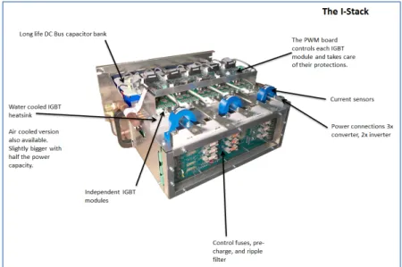
3.3.3 Integrating the rectifier and the inverter in a module, the I-Stack™ ... 36
3.3.4 Component selection for the I-Stack ... 38
3.4 IGBT selection ... 38
3.5 Heatsink design ... 42
3.6 Capacitor bank with DC busbars design ... 45
3.7 Leakage inductance management ... 53
3.8 Mistake-proofing the equipment ... 55
3.9 Advanced converter protections ... 55
3.10 Long life design philosophy ... 60
3.12 Innovative capacitor bank life monitoring ... 61
3.13 Other component life monitoring techniques ... 64
3.14 Safety aspects of capacitor banks ... 64
3.15 Other safety aspects related to power converters ... 68
CHAPTER 4 SOFTWARE DEVELOPMENT FOR THE I-STACK™ ... 71
4.1 Software for everyone; the “Power PLC” ... 71
4.2 Graphical programming example ... 73
4.3 Diagnostic adapted for a wide audience ... 74
4.3.1 Remote diagnostic ... 78
4.3.2 Fault recording and analysis ... 79
4.3.3 Connectivity ... 81
4.3.4 Web Interface ... 82
CHAPTER 5 TOWARDS A COMPLETE SOLUTION ... 85
5.1 Presenting the I-Pack™. ... 85
CHAPTER 6 APPLICATION EXAMPLE ... 89
6.1 Ozone generator power supply ... 89
6.2 Legacy PSU technology ... 93
6.3 System improvements when using the I-Pack™ ... 96
6.4 Details of the application ... 101
6.5 Alarms and faults for the ozone PSU ... 103
6.6 Final word on ozone PSU application ... 105
6.7 Flexibility for other applications ... 106
CONCLUSION ... 107
FUTURE WORK AND RECOMMENDATIONS ... 108
ANNEXE I ... 111
XIII
LIST OF TABLES
Page
Table 0.1 Examples of successful applications for power electronics ... 2
Table 0.2A Examples of applications ... 5
Table 0.2B Examples of applications (continued) ... 6
LIST OF FIGURES
Page
Figure 0.1 I-Stack power converter ... 4
Figure 0.2 Simplified product design cycle ... 7
Figure 1.1 Infineon’s complete IGBT bridge ... 17
Figure 1.2 Analog Devices' ADSP-CM41x Mixed-Signal Control Processors ... 18
Figure 3.1 AC/DC/AC power converter schematic ... 27
Figure 3.2 Power converter used as an upgrade module for legacy thyristor PSU ... 31
Figure 3.3 Industrial control panel with PLC and field terminals ... 31
Figure 3.4 Simulation of a rectifier PWM waveforms operating at 1 kHz ... 33
Figure 3.5 Real Rectifier current and voltage waveforms ... 34
Figure 3.6 Water cooled I-Stack™ ... 36
Figure 3.7 IGBT module ... 39
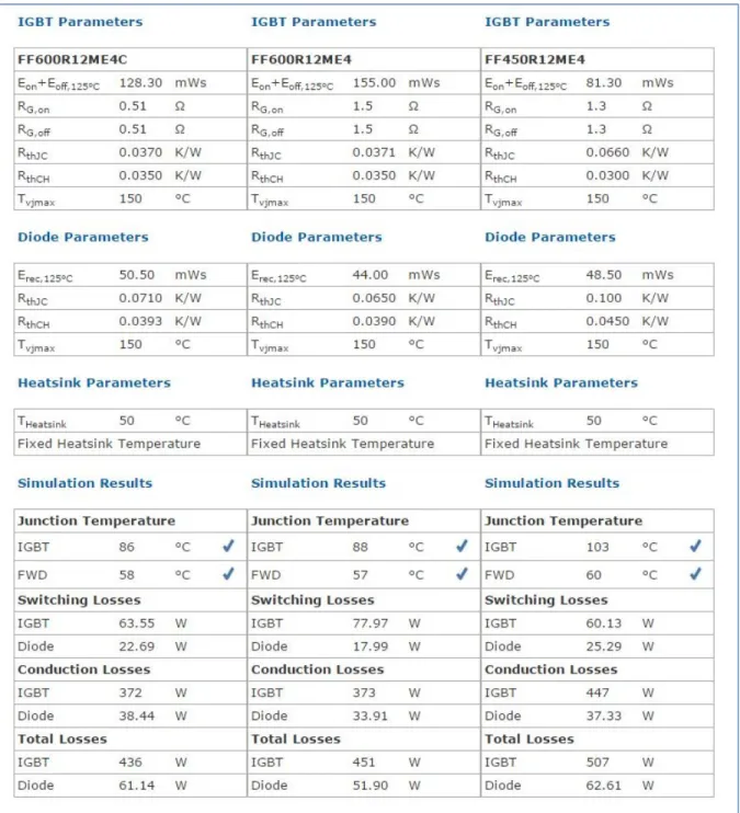
Figure 3.8 IPOSIM™ Results for different IGBT modules ... 40
Figure 3.9 IPOSIM™ IGBT losses evaluation sheet ... 41
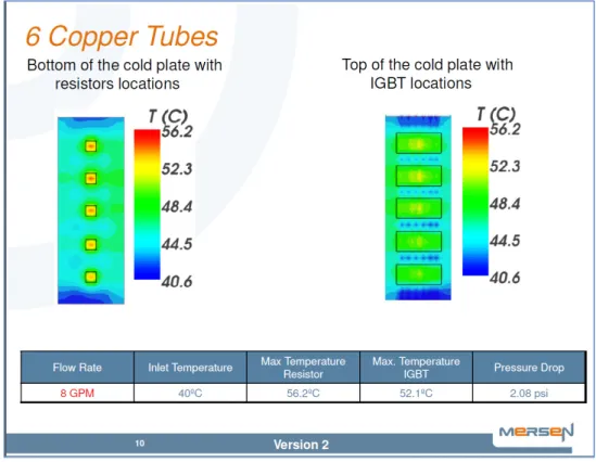
Figure 3.10 Water-cooled heatsink temperature profile simulation by Mersen... 43
Figure 3.11 I-Stack with air-cooled heatsinks ... 44
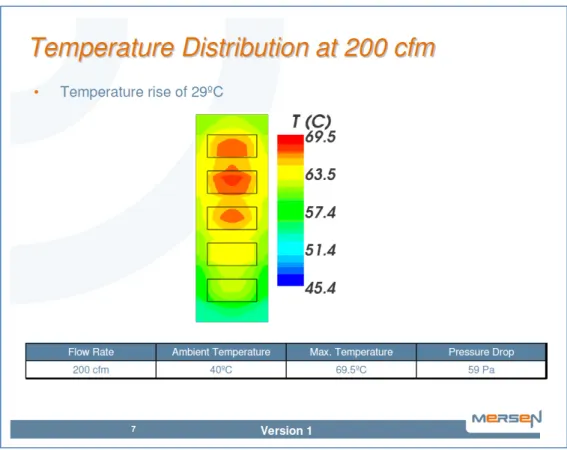
Figure 3.12 Air-cooled heatsink temperature profile simulation by Mersen ... 45
Figure 3.13 Electrolytic capacitor ESR vs frequency ... 46
Figure 3.14 Ripple current multiplier for electrolytic capacitors ... 48
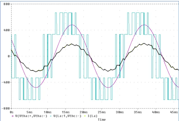
Figure 3.15 Inverter current and voltage waveforms for an ozone application at full load. . 48
Figure 3.16 Electrolytic capacitor sizing sheet for 1/5 of the current ... 52
Figure 3.17 Table of suitable electrolytic capacitors ... 52
Figure 3.18 Gate driver over voltage protection ... 54
Figure 3.19 Capacitor bank, heatsink, and IGBT modules during assembly ... 54
Figure 3.20 Example of an IGBT module with a matched gate driver ... 56
Figure 3.21 Power Integration’s Scale™-2 IGBT Gate driver diagram ... 57
Figure 3.22 Software converter protection adjustment parameters ... 58
XV
Figure 3.24 Damage to a capacitor bank from imbalanced series connection ... 63
Figure 3.25 IGBT damaged by an explosion ... 66
Figure 3.26 Two I-Stacks mounted in a cabinet with auxiliary components ... 67
Figure 4.1 Example of power calculation code (partial) using SimulinkTM ... 72
Figure 4.2 Code snippet of a power calculation function using "C" language ... 73
Figure 4.3 Graphical programming example ... 74
Figure 4.4 Oscilloscope and diagnostic information ... 76
Figure 4.5 Service report ... 81
Figure 4.6 Example of the maintenance web page that can be viewed remotely ... 82
Figure 4.7 Web interface with pop-up information windows ... 83
Figure 5.1 The I-Pack™ power converter ... 85
Figure 5.2 Single line diagram for an I-Pack ... 87
Figure 5.3 I-Pack with the front open showing the I-Stack ... 87
Figure 6.1 Ozone generator showing the tubular dielectric electrodes ... 90
Figure 6.2 Ozone generator electrical model ... 91
Figure 6.3 The process of producing ozone in a generator ... 92
Figure 6.4 A 400kW ozone generator and its PSU in the background ... 93
Figure 6.5 Thyristor PSU schematic diagram ... 94
Figure 6.6 Thyristors PSU, rectifier waveforms, and power quality results ... 95
Figure 6.7 Door-mounted alarm annunciator and analog meters ... 96
Figure 6.8 Simplified diagram of an IGBT PSU ... 97
Figure 6.9 Complete I-PSU™ system constructed from an I-Pack power converter ... 99
Figure 6.10 Single line diagram for a two power stage I-PSU™ ... 100
Figure 6.11 A 1.2MW ozone generator I-PSU™ ... 101
Figure 6.12 Low power inverter operation ... 102
LIST OF ABREVIATIONS AND ACRONYMS
A Ampere
AI Artificial Intelligence
AHF Active Harmonic Filter
BIOS Basic Input Output Software
CSA Canadian Standard Association
DE Distributed Energy
FACTS Flexible AC Transmission Systems
FFT Fast Fourier Transforms
HIL Hardware-In-the-Loop
IAS Industry Applications Society
IEC International Electrotechnical Commission IEEE Institute of Electrical Engineering Engineers IGBT Insulated Gate Bipolar Transistor
IoT Internet of Things
IPEM Integrated Power Electronics Module
M2M Machine to Machine
OEM Original Equipment Manufacturer
PCB Printed Circuit Board
PEBBs Power Electronics Building Blocks
XVII
PLC Programmable Logic Controller
PLL Phase-Locked Loop
PSU Power Supply Unit
PV PhotoVoltaic source
PWM Pulse Width Modulation
RMS Root Mean Square
RoHS Restriction of Hazardous Substances
STATCOM STATic COMpensator
THD Total Harmonic Distortion
UL Underwriters’ Laboratory
V Volt
VA Volt-Ampere
VSC Voltage Source Converter
VSI Voltage Source Inverter w.r.t. with respect to
INTRODUCTION
Our economy is based on technologies that make life more comfortable and that facilitate our work. A large portion of this technology is implemented in machinery and processes developed and produced by Original Equipment Manufacturers (OEMs). Their objectives are to reduce various costs and improve the desirability of their products to increase their share of the various markets they are involved in. A basic premise of this work is that power electronics converters can contribute greatly to the products and processes that the OEMs are developing. Unfortunately, their adoption has been slowed down by their complexity and the general lack of awareness of their potential contribution.
This work begins by showing how the use of power electronics is helping improve the efficiency and the performance of various processes and equipment. Variable speed drives and DC power supplies are the original applications for which power electronics technology has been developed, but it can contribute to several others. An example of these applications is the hybridization or replacement of internal combustion engines with electric motors in some models of cars. While electric cars have been available for more than a hundred years, the low performance level obtained with early electro-mechanical technology limited their popularity. Suitable power electronics converters only became available near the turn of the millennia. This finally brought electric cars to a level of performance attractive to a wider market.
This success story is likely to be reproduced when power electronics converters will be used in other applications. The following table illustrates a few potential candidates.
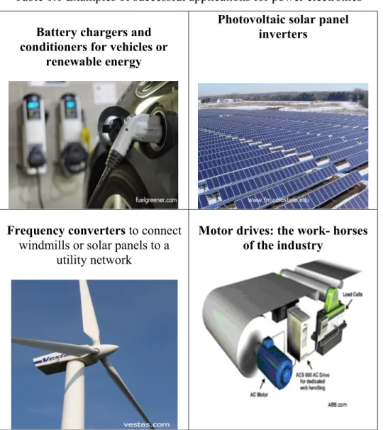
Table 0.1 Examples of successful applications for power electronics
Battery chargers and conditioners for vehicles or
renewable energy
Photovoltaic solar panel inverters
Frequency converters to connect
windmills or solar panels to a utility network
Motor drives: the work- horses of the industry
Pictures taken from indicated web sites in early 2006
Based on previous success in fields such as transportation and energy, researchers and industry commenters (Admin, 2013) are convinced that many other processes and products can benefit from power electronics converters.
One factor that is slowing down the diffusion of power electronics is that developing a new process or equipment requires skills and know-how specific to the field of application. For example, to develop a new chemical process, one must be at least an expert in industrial chemistry. It is not likely that an electrical engineer will develop advanced chemical processes.
3
Therefore, new processes development is usually conducted by a small team of experts (OEMs) that rarely include power electronics engineers. Therefore, the benefits that power electronics could bring to the process or equipment are not always recognized. When they are, the OEMs must either set up a power electronics engineering section with their own lab or sub-contract the power electronics converters’ design to another firm. Both choices are time-consuming and expensive; not what a fast-paced application development team is looking for.
A possible avenue of simplification is to develop a power electronics converter architecture that could be used by any OEM team with a minimal amount of power electronics know-how. This would be the equivalent to the Programmable Logic Controllers (PLCs) so widely used to automate machines and processes. When using a PLC, one doesn’t need to be a microprocessor expert and develop printed circuit boards to automate a machine, but simply must respect the voltage and current levels of the inputs and outputs. Even the programming is simplified by using graphical ladder language that resembles the electrical schematics that electricians are familiar with.
The objective of this work is therefore to develop a power electronics converter that will be as easy to use as a PLC, so that OEM staff can configure and program it to improve their process, without needing expertise in power electronics. It is very likely that this will open the door to a wider range of applications that are not yet taking advantage of power electronics technology. The other advantage of simpler power electronics is that it will allow a greater number of teams, even those with limited resources, to develop their own solutions to machinery or process problems. This is likely to increase the quantity of innovative products designed to solve the technical challenges our society faces.
The solution proposed in this document is the I-Stack™ power converter shown in Figure 0.1. I have conducted the development of this power converter for my employer. This section gives an overview of some of the application needs that led to its design. It presents the motivation behind the design philosophy. Chapter 1 concentrates on identification of the problem and what others have done about it. The following chapters show how a solution can be implemented
in the form of an industrial power converter. The objective of this document is not to provide all of the design details, but to trigger a reflection in the power electronics community on the subject of usability of power converters and the simplification of their design. Finally, an example of an application in the water treatment industry is presented to validate this work. The product line covers the 100kW to 2.4MW range.
Figure 0.1 Imalog’s I-Stack power converter
Potential applications for power electronics converters
There are dozens of applications where power electronics can be used to improve a product or process performance. A simplified list of the applications is provided in 0. The scientific literature is filled with research detailing how various forms of electrical power can be used to achieve useful results. This list is a good starting point for those looking for challenges. In these applications, the electrical power needs to be controlled in specific ways. The electricity supplied by the utility company is rarely provided in a form suitable for these applications. Power electronics converters are one of the possible solutions to transform this electricity into a suitable form.
5
Table 0.2 A and B, illustrate some of the well-known applications where power converters are presently used or will be used in the near future.
Table 0.2A Examples of applications
Large battery chargers and conditioners for vehicles or renewable
energy
M2G (Motion to Generation) converter,
shock absorbers with energy recovery, stability
control, hybrid motors
Electric services and propulsion for airplanes
Table 0.2B Examples of applications (continued)
Electro-magnets for frictionless bearings, load
handling, and linear motors
Chlorine generator (Sodium hypochlorite) to
transform chemical products from one form to
another
Electro-separation of liquids for petroleum extraction and oil removal
from other substances
Frequency converters to connect windmills or solar panels to a utility network
Induction heating and metal processing with
even and precise temperature control
Plasma torch power supplies
7
Solutions analyzed in this document
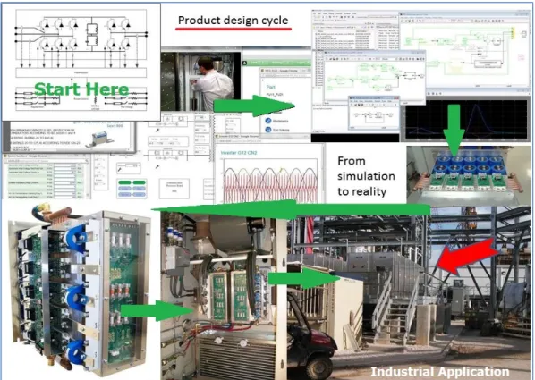
This section presents the development effort and the philosophy behind a new line of power electronics converters specially designed to be used by the product and process developer community (OEMs). Figure 0.2 is a simplified illustration of the power electronics converter design process from idea to application.
Figure 0.2 Simplified product design cycle from conceptual design, simulation, programming, fabrication, tests, to installation at an industrial end-users site
This simplified illustration of the design process from the idea to the industrial usage is based on a real application. It skips over millions of details but gives a roadmap to young designers venturing in the field of power electronics. It starts in the top left corner where the initial research for a solution has led to an electronic circuit. The designer then uses various computer tools and measurements on test prototypes to come up with a working design (top section). After many months of work, the electrical design is then implemented on a physical unit
(middle right). Suitable component selection is a crucial part of this process, as even the best components are unreliable when used improperly. Iterations are common, and returning to the beginning of the process (when the results don’t meet the expectations) is a real possibility. The mechanical and electrical designs are then integrated into a finished power converter (bottom left corner). The work to fulfill a complete application doesn’t stop there as months of testing are still needed and a suitable cabinet with auxiliary components must be provided (bottom center). Finally, the system engineering team can integrate the power converter into a complete solution to satisfy the needs of an industrial customer. Months later, the complete system can be installed at the industrial site, followed by weeks of commissioning work (bottom right). In the case of the I-PSU™ presented in the last chapter, this process took a few years.
CHAPTER 1
WHAT SLOWS DOWN POWER ELECTRONICS ACCEPTANCE 1.1 The broken connection with potential users
Power electronics is different from the technologies used by mechanical or chemical process engineers. What could be done to help Original Equipment Manufacturers (OEMs) and process developers succeed in using power electronics converters? This lack of familiarity creates a barrier that is very difficult to cross for many product development teams. A way to reduce this barrier must be found to help them recognize, understand, and use power converter technologies as a solution to their problems. This is crucial as OEMs will not use this technology if they are not aware of its benefits.
We can divide the problem of making the power converters technology more popular into two parts:
Finding a way to design and present a power electronics converter to facilitate its acceptance and its use by OEM staff;
Finding topologies and accessories needed to cover as many applications as possible.
To solve the first part of this problem, one must gain a better understanding of OEMs’ product development process. A basic review of the literature on the subject of technology innovation and communication between different technical groups shows that people choose what they are familiar with or what excites their curiosity. In their paper, (Barham et al. 2013) cover the ambiguity aversion that affects the adoption of new technologies. Basically, people don’t like what they don’t understand. Also, (Chen et Granitz, 2012) showed us that the perception of the usefulness of a high technology product is key to its adoption. The trick is to convince customers that the product is useful. (Lanzolla et Suarez, 2012, p836) explain how “the information diffusion mechanism can help explain the time to technology use”. They also
support the case that customers need to know about a technology before electing to use it. These authors’ work and our own 25 years of experience working with OEMs, was used to formulate what are, in our opinion, three important guidelines for new product acceptance:
To accept a new technology, one must first learn of its existence. This seems trivial, but it is a major problem for power electronics converters as this technology is not visible. It is almost always hidden inside the product and its function is not publicized. Most people use some power electronics without knowing it. Here are some suggestions to promote the use of power electronics converters to OEMs:
a) Organize events to inform people about converters, either in related technical publications, at “their” conventions, through publicity, or through word of mouth;
b) Have presentations in a language that mechanical or process-trained designers understand. This includes the language itself as well as the technical jargon used. Documents should not be written by electrical engineers for electrical engineers as they often are;
c) Overcome the cultural barriers and bypass their “interest filters” since people prefer to use technologies from their own field of expertise to solve problems: turn power electronics converters into one of their tools.
To be motivated, the designers must realize the usefulness of the technology from examples or descriptions of its use in their field of interest. They must perceive an advantage to compensate for the effort needed to learn how to use it. The designer’s motivation can be increased by providing instant gratification. The product must reward them immediately, showing quick results instead of having to work on it for months before running the first tests. Supplying working demonstrators is a way to achieve this.
The technology must be available to the OEMs in a form that they can use. Most people shy away from technologies that are too difficult to use. The difficulty can come from its
11
complexity but also from having to justify a high development cost or a long lead time for the project.
These guidelines are seldom followed by power electronics (PE) manufacturers. Their presentations of power converters capabilities are usually tailored to the electrical engineering community. This is because most of the PE manufacturers are still operating under the belief that their equipment must be customized by their own power electronics engineers for each application. This is likely to be true once a solution has been tested and needs to be optimized, but the PE manufacturers never get to this point if the potential user doesn’t buy it. The result is that power electronics converters application knowledge is not transferred to the people that are often specialized in mechanical technology or chemical processes. They do not see how power electronics technology can be used in their application to solve their problems.
1.2 Communicating with people of different technical backgrounds
The following section presents more details on ways to simplify the concepts of power electronics and to make them accessible to most designers. This process begins with learning how to communicate the general concepts, and is followed by methods to simplify the use of this technology to make it accessible to the intended audience.
1.2.1 The technical language barrier
Education professionals have confronted the technical language barrier for centuries. They found that education of individuals is more than just telling them about something. In their book “Telling Ain’t Training”, (Stolovitch et al., 2002) tell us that the information that we acquire is rarely turned into knowledge unless we already have similar concepts to relate to in our mind. In the most common learning process in adults, the links formed by new concepts in our memory need to be anchored to already-existing memories in order to be processed.
This makes it very difficult for people with different backgrounds to educate each other as they are lacking common memories or ideas. The words and concepts used by the communicator (teacher) must be carefully chosen to trigger connections with the learner’s memories. This implies that to educate and motivate people to use power electronics converters in their work, the converters must be described using terms and examples commonly used by mechanical and chemical engineers instead of the typical electronics jargon that we use every day.
As scientists, we take comfort in believing that since mathematics is a universal language, we can use it to communicate effectively with all our peers. Unfortunately, effective communication, even amongst technical people, requires more than exchanging equations and numerical results. Even when we agree on a specific communication language (such as English), every specialty has its own lexicon to express concepts that use the same mathematics. An example of this is a sinusoidal oscillation. The mechanical engineer will call it a vibration and use terms like inertia, spring constant, viscous dampener and Newton’s second law of motion, as shown in Equation 1.1.
+ + kx = cos(ωt + ) (1.1)
To represent a similar concept, electrical engineers use inductance, capacitance, and resistance, that may be expressed as shown in Equation 1.2.
+ + = ωV cos(ωt + ϕ) (1.2)
When the two engineers talk about oscillation, they have difficulty understanding each other simply because they use different mental images and terms to express the same basic concepts. This means that some education about the other’s “language” is needed to bridge the gap and to facilitate the understanding of power electronics converters by more people.
13
1.2.2 Generating interest
Another important education concept is given in “Building EXPERTISE, cognitive methods for training and performance improvement” (Clark, 2008). The author provides many techniques to facilitate the transfer of knowledge from one party to the other. Chapter 16 is particularly useful to this work. It contains valuable tips on how to motivate the learner. The main task is to find ways to make the abstract concepts of power electronics attractive to those who are passionate about challenges from other fields. In other words, our subject must be adapted to the target audience.
1.3 The technical innovation
The innovation presented here is not as much a way to educate the community of product and process designers (OEMs) but a way of developing power electronics that can be used by the OEMs’ staff, and presenting it to them. It is easier to train a few power electronics engineers to use terms and concepts familiar to an OEM designer than it is to train tens of thousands of OEM designers to understand the details of power electronics. It is especially true that in this case, the power electronics engineers (us) are the ones trying to convince the OEM designers that our technology is beneficial to their work.
The innovation is therefore making power electronics accessible to “the others”. While it is new to our field, a similar revolution has already taken place in the computer industry. In the early years (1940-60’s), someone basically needed a PhD in electronics or computer science in order to use a computer. Today, five-year-old (and even younger children) can do amazing things on a tablet. This wasn’t achieved by providing advanced training to toddlers, but by making computers simpler to use. Can this be repeated? Let’s see what our power electronics experts are doing to make our field more accessible to the masses.
The IEEE Industry Applications Society (IAS) had a whole conference on this subject in 2004 in Italy (reference?). As always, many papers were presented and expert wisdom was shared. Blaabjerg et al. in their paper “The Future of Electronic Power Processing and Conversion” (2005) described how the field evolved over the years and where it was expected to go. One of their points was that the demand was not so much for basic products and components but for whole systems solving complete problems. People didn’t want IGBT modules, inductors, and drivers; they wanted a whole battery charger that only needed to be plugged in the wall. This expert panel also foresaw a large demand for energy related applications and expected that many practical applications would develop over the next 25-30 years. Since the conference was held ten years ago, we can confirm that they were right and we are just at the beginning of the revolution. Many real applications are presently operating in solar, wind energy and electric vehicles. They also predicted a proliferation of standardized power supplies. This is yet to be seen on a general level, but it is true for the computer industry. You can now re-charge your telephone or tablet with any USB charger found lying around the house. It looks like the world is waiting for something similar in other applications. Finally, they predicted the use of intelligent controls to facilitate energy management. This too is not yet widely available for real life applications, but it is being worked on.
Our own industrial experience corroborates the opinion of these researchers, motivating our effort to develop a power electronics solution as complete as possible, using a familiar interface for its operation.
1.4 The standard route
Once the designers’ interface and needs are understood, the next step is to define what solution can solve as many problems as possible. A few researchers have published high level analyses of power converter topologies applicable to the most popular applications. Chakraborty and his colleagues (2009) provided an interesting analysis. They tell us that “[t]he integrated power electronics module (IPEM) based back-to-back converter topologies are found to be the most
15
suitable interfaces that can operate with different DE [Distributed Energy] systems with small or no modifications” (page reference). This is important as they identified a flexible architecture that reinforces the IPEM concepts developed by many other researchers over the years. Like others before them, they also point out that a standardized interface, not only between the building blocks but with the users, is needed and challenges the IEEE to continue to work on it. They point out that “The concept of power electronics building blocks (PEBBs) provides a way to hardware standardization of power electronics systems” (page reference). Finally, they confirm that the standardisation of the interface between the different modules, both hardware and software, is a real challenge.
Their conclusion is valid but not likely to be implemented anytime soon. This opinion is based on my own understanding of the power electronics manufacturers’ mentality. This may not apply to all of them, but working for a few different manufacturers and having done business with many others over the years helped develop this opinion. While some manufacturers have tried standardizing their interfaces, it has not been a widespread commercial success. The reason is found in the laws of the market. Manufacturers need to differentiate their products from the competition. In our field, the main product differentiators are price and functionalities, as aesthetics rarely influence our customer’s decisions. Once the IPEMs are perfectly standardized, product manufacturers can only compete on price, since they all perform the same function. This pressure on price reduction limits innovation because an easy way to reduce the cost of an item is to stop investing in improvements. An argument can be made that they could innovate by implementing module technologies with reduced cost. That is true, but it is very limited if a strict standard is kept. Let’s take as an example different manufacturers building DC-DC converter to meet a standard specification for electric vehicles. It needs to convert 400VDC to 24VDC for accessories. If manufacturer “A” uses IGBT switching at 50kHz while manufacturer “B” uses SIC MOSFETs switching at 5MHz, are the two converters meeting the same standard? They perform the same function but their size or weight may be different because of the smaller magnetics from manufacturer “B”. The two converters are not likely to have the same power losses and their EMI emissions are likely to
be different. Therefore, to switch between “A” and “B”, the car manufacturer may need to adapt the mounting of the module, its cooling requirements, and re-do the EMI testing.
This example is an over-simplification as to why many have tried to define a standard but few have succeeded commercially. A noteworthy exception is the case size for some DC-DC converters such as “half brick, quarter brick”, but even in this case, the electrical specifications can vary from one manufacturer to another. Technology advances so fast that standards are often obsolete by the time they come out. In the past, when standardizations took hold, it usually resulted in the elimination of many players as the price goes down. This was then followed by the virtual abandonment of the standard as higher performances were established by products not restricted by the old standard.
A major disadvantage of using standards is that they are based on compromises. This means that you don’t get the best performance but an average product. In his paper on standardisation, (Uusitalo, 2011) tells us that standards are difficult and risky. They cannot be applied to all subjects and standard failures are costly. Successful standards tend to be applied at higher application levels, leaving flexibility for the manufacturers to differentiate themselves with functionalities and performance. The USB port on computers is a good example where the interface is standardized but the implementation of the device connecting to it is extremely flexible. While their operation and functions are similar, many different sizes and types of memory sticks and accessories can use the USB port.
1.5 The manufacturers’ building block route
The trend we are witnessing in the industry is that more and more component manufacturers are offering their products in building blocks instead of in basic component form. This is seen for sensors, controllers, and power semiconductors. While the interface between these building blocks is not standardized at the industry level, each component manufacturer tries to simplify its own interface and keep it consistent over their product range, and often across generations.
17
This greatly facilitates the task for their customers (the end-product designers) who don’t need to completely re-design their product each time the component manufacturer makes an improvement.
Using this building block technique, each end-product designer must choose a group of blocks that are best suited to their product needs. This usually “lock them up” to specific manufacturers as alternate sources are seldom available. This disadvantage is compensated by the relative ease of integration of the blocks, freeing more time to concentrate on the end-product and its application. Here are a few examples of these blocks:
Figure 1.1 Infineon’s complete IGBT bridge simply needs a capacitor bank, a controller, some inductors, and auxiliary components
Taken from https://www.infineon.com/cms/en/product/power/igbt/igbt-stack/channel.html?channel=ff80808112ab681d0112ab6a454b047c
(December 2016)
Figure 1.2 is another example of building block intended to facilitate the design process. Simply add the power semiconductors, the magnetics, auxiliary components, and the software.
Figure 1.2 Analog Devices' ADSP-CM41x Mixed-Signal Control Processors
Taken from www.analog.com/en/products/landing-pages/001/adsp-cm41x product- family.html (December 2016)
One can conclude that the partial standardisation of building blocks has facilitated the task of the end-product designer. Unfortunately, we are still far from a complete power converter solution that can be purchased by an OEM to be used in a new machine design. To use these blocks, one needs specific power electronics know-how. The OEM must still rely on a power electronics converter manufacturer to integrate the building blocks, magnetics, and controls, in an enclosure suitable for their application.
CHAPTER 2
IDENTIFYING THE NEEDS 2.1 Hypothesis for product development
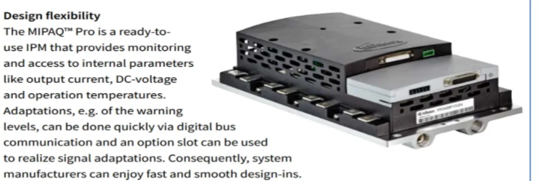
Researchers have explored the power electronics design complexity issues and developed partial solutions based on standard modules such as the PEEBs and its commercial analog, the intelligent power module (IPM). These modules greatly facilitate the design of power electronics converters but are far from being a complete solution that could be used by an OEM. One must still be a power electronics expert to produce a complete system. One must add special inductors, capacitor banks, heatsinks, current and voltage sensors, EMI filters, some form of digital controller with an interface, and program the whole thing with specialized control techniques. In short, a power electronics expert is needed to complete it.
Most power converter manufacturers offer semi-completed converters and promote them to the OEM community. They usually have moderate success with the concept, which indicates that they aren’t completely meeting the market requirements. Their advertisements show that they are still geared toward an intense customization of their design before an OEM can use it. This means that the OEMs must disclose a fair amount of details about the application’s intellectual property (IP), pay for prototype development, and wait months before trying it in their process. Additionally, the OEMs take on the high technical risks of using newly developed equipment that come with their own set of bugs, hampering the development of their application.
As presented in the previous sections, OEMs need a complete power electronics converter that can easily be scaled to various application sizes and meet different applications. To maximize flexibility, most of the functionalities should be implemented in the software. The reference software provided with the product should be easily adaptable by the OEMs to meet their
specific needs. A few software examples are needed to help the OEMs’ staff to progress rapidly and get the early success needed as discussed in detail in Section 2.4, item C.
While a general power converter may not be optimal for the specific application, it is meant to be easy to use by a professional concerned about evaluating how power electronics can solve their immediate mechanical or chemical process issue. Once the OEM’s developer is satisfied with the results, they will be motivated to invest in the optimization of the power converter for their specific needs.
Based on the OEM’s needs and the above discussion, we have narrowed our development down to five high level design objectives. They will be discussed in more detail in the following sections.
A. The products must be complete systems fulfilling all the power conversion needs of the OEM;
B. The power electronics solution must be accessible, presented with terms and concepts understood by the OEM’s staff who are not trained in electronics;
C. The products must provide instant gratification: use the “plug and play” philosophy;
D. The converter topologies should be suitable for the applications;
E. The product must be reliable with protection against misuse.
21
2.2 What does a complete power converter solution include? (Item A)
A complete power converter solution should include at least the following:
• The application software or at least some examples that can be modified; • A processor board that interfaces with the power electronics;
• Some means of user interface, such as keypad and display; • An auxiliary power source as needed to operate the system; • A cooling system, or at least a simple interconnection; • The power electronics converter;
• Protection for the personnel and the equipment; • All the fuses, contactors, inductors, transformers; • An enclosure.
2.3 How to produce an accessible presentation of the product? (Item B)
For the power electronics solution to be accessible, it must be presented using terms and concepts understood by an OEM’s designer that is not trained in electronics. The application documentation needs to be written by somebody who understands those fields to use terms of that trade. Similarly, the user manual needs to be understood by a non-expert in power electronics. Jargon relating to electronics is to be avoided or at least minimized. A separate maintenance manual or a section of the user manual can be produced with more electronic jargon intended for people trained in electronics. A good example of this is the user manual produced by car manufacturers. It simplifies the operation of an extremely complex machine to make it accessible to most people. The computer industry is an extreme example of this as the user manual has been simplified to a few pages, informing the user mostly about safety and how to start the equipment. The rest of the operation is arguably “intuitive” or learned using the built-in help pointers.
2.4 How to provide instant gratification? (Item C)
Use the “plug and play” philosophy. One should only need to provide power to the equipment to see it come to life. Built-in protections should ensure a safe operation even in an incomplete system. This means that the operator interface comes to life but the power is not applied to the output until a valid load is detected. This way, the user is encouraged to continue its effort and can get familiarized with the product even if the whole application is not yet ready.
2.5 Which converter topology is suitable for many applications? (Item D)
While many power converter topologies exist, our initial market is for large applications in the tens to hundreds of kWs. These are mostly operated from three phase supplies. In agreement with many researchers as presented by (Chakraborty, Kramer et Kroposki, 2009), we have also found the back-to-back converter topology to be suitable for the applications we intend to service. The decoupling provided by the DC bus gives more flexibility by allowing a semi-independent operation between the input and output. This leads to simpler control strategies than seen on tightly coupled topologies, such as single stage matrix converters. In a back-to-back converter topology, the active rectifier section is controlled independently from the inverter section. When properly sized, the DC bus absorbs most of the line or load imbalances, harmonics, and transients experienced by most converters. Of course, the power balance needs to be controlled to maintain the DC bus voltage but this can be achieved using a PI controller.
Another problem of the single stage matrix converter is that the filtering of the load ripple is done on the AC side where the filter is exposed to the line AC. It is therefore difficult to have a large filter because it will affect the line and will be subject to resonance. While one can design this filter to be stable with the controller, nobody can guarantee its operation in a real application. This is because many plants have multiple harmonic sources that inter-modulate and include variable parallel resonances that are outside the control of our converter. The IEEE-519-2014 Recommended Practices and Requirements for Harmonic Control in
23
Electrical Power Systems is a comprehensive document guiding engineers and setting acceptable harmonic levels. One look at this document gives a good idea of the complexity of the task.
Finally, the double stage AC/DC/AC converter isolated by a large capacitor bank is better suited when the load ripple is large, such as for a single-phase load or a high turn-down chopper. The DC bus filters out most of the ripple and helps maintain the feeding line power quality.
2.6 How to implement a reliable product with suitable protections? (Item E)
Designing a reliable product is not a question of chance. One must start with a good circuit and select the right components. If ample safety margins are built-in, one should expect a reliable operation as discussed in Section 3.10. At least, that is how it used to be. Today’s products rely heavily on software that comes from libraries maintained by other entities. It becomes very important to re-test the product after each compilation as “updated” libraries may produce unwanted behaviors.
Protections are extremely important aspects for power converters. One must think about personal protection as much as equipment protection. The level of energy handled by power electronics make them potentially dangerous. One must therefore follow the applicable safety regulations during prototype work, as well as during final product development, as discussed in Sections 3.14 and 3.15.
In conclusion, developing a new power converter begins with an identification of the users’ and applications’ needs, otherwise the converter is not likely to have commercial success. This chapter supported the case that power electronics is complex and its usage must be simplified to gain market acceptance. One way the manufacturers implement this simplification is
through the development of pre-designed modules containing ever-increasing functionalities. The other way is through standardisation. We argued that the modular approach facilitates the task of the power electronic designers but is still too complex for the end users. Similarly, some standardisation is useful but may limit innovation. This led us to formulate five high level design objectives for the power electronics engineer intending to design converters adapted to the end users.
CHAPTER 3
ONE STEP CLOSER TO THE COMPLETE SOLUTION
As described previously, power electronics applications are usually associated with improving energy efficiency of machinery and industrial processes as well as enabling cleaner processes than those traditionally used in industrial applications. Major examples are hybrid and electric cars reducing CO2 emissions, and electro-chemistry eliminating or replacing carcinogenic chemicals with less toxic ones. Given this performance, one would expect that potential users would rush to find ways to include power electronics into their technologies but it is rarely the case. I observed this lack of interest during our thirty years of work in the industry. A possible explanation is that power electronics is misunderstood by those in the branches of science and engineering who develop machines and processes. Unfortunately, electrical engineers seem to reinforce this by using specialized lingo whenever possible.
To circumvent these difficulties, this work proposes that electrical engineers should use ideas and concepts in their communication that relate to the language of people from other fields. Another facilitator is to design complete power converter packages that can be used with minimal knowledge of how it is made as opposed to the modules commonly available on the market. These converter packages should be made as user friendly as possible by including an easy to use interface and be self-protecting against most misuse. This chapter presents some solutions to the above problems. It will be followed by a discussion of the software and hardware functionalities in the next two chapters. Later, chapter 5 will briefly cover the I-Pack™ that gets close to the optimal complete solution and chapter 6 will present a large application for our power electronics converters as power supplies for ozone generators.
3.1.1 Designing for industrial applications
At Imalog, the main applications were for large power supply units (PSUs) used in the ozone generation industry. Reliability and ease of maintenance are paramount for an equipment that has a useful life of twenty years. We had to come up with a proven topology that meets the requirements of high power quality on the line side. Simultaneously, performant control of the power to the ozone generator is needed. The generator is a non-linear load that requires specific control strategies and protections. All of this is needed while meeting industrial safety requirements at a competitive price.
Based on these considerations, we chose to begin our work with an AC/DC active rectifier followed by a DC/AC inverter. This configuration is often called a back-to-back converter. The voltage DC bus is fitted with a generous capacitor bank to filter the high ripple current produced by the single-phase load. This also decouples the two IGBT bridges, preventing the inverter’s harmonics from reaching the supply line. We could have chosen an AC/DC buck rectifier or an exotic matrix converter, but the back-to-back converter topology is well understood in the industry and has been shown to be reliable for the hundreds of N-PSUs that Imalog has produced since 2001. Past references are very important for an industrial equipment manufacturer. Therefore, the chosen topology is conservative. The innovation is in the implementation and added functionalities.
The active rectifier is a typical three phase, six IGBT bridge and the inverter uses a single phase, four IGBT, H-bridge configuration. Both bridges are two levels, four quadrants hard commutated, from a voltage controlled DC bus as shown on figure 3.1.
27
Figure 3.1 AC/DC/AC power converter schematic. (Top half) The six pulses IGBT rectifier (left) is followed by a capacitor bank (middle) and then a single-phase H bridge inverter (right). The control electronics and auxiliary functions are shown in the bottom section.
We decided to integrate the active rectifier and the inverter on the same converter assembly for cost reduction reasons. In the main applications we are targeting, the two IGBT bridges are needed. A convenient way to reduce the cost was to minimize the redundancy of components we would have had with two independent assemblies. The savings are:
The heatsink does not double in cost even when we increase its length by 60% to accommodate more IGBTs. It also cuts the water piping connections in half;
There are savings on the electronic boards as common sections such as the power supplies can be shared.
The interconnection of the two DC buses is also simplified by using continuous busbars. It minimizes the parasitic inductance introduced between the IGBT bridges;
One enclosure is also less expensive than two smaller ones.
3.2 Converter capacity consideration
The following section explains why Imalog chose to design a 200kW power converter. Other designers working on different applications are likely to come up with other power capacity, but here are a few of the reasons for this choice:
Most importantly, we had an application for it. The ozone generator power supply unit application will be discussed in chapter 6. This converter size allowed us to cover a range between 100 kW and 2.4 MW using repeats of the same components and magnetic design. To go above 200 kW, we simply placed multiple complete converters in parallel;
A 200kW design is in the range of many of the other industrial applications that are being investigated by process researchers as discussed at the beginning of this document. This converter needs to prove the viability of the design in the intended power range of the applications;
A small prototype is not usually representative of the larger version. Power electronics doesn’t scale up very well. Many of the parasitic elements such as leakage inductance grow rapidly with power. Control strategies are also affected by the equipment size. With today’s components, one can easily design a 10 kW hard-switched converter switching at 50 kHz but it is almost impossible, or at least very expensive, to switch at this frequency for 200 kW or
29
more. The reduced frequency possible at high power greatly reduces the speed of response of the control loops and affects the performance that can be obtained with a given controller. The common industrial strategy of starting with a small prototype and up-sizing it later is riskier as design parameters that were negligible or easy to solve in a small system can lead to technological impasses on larger systems. This means that the scaled-up controller is not likely to respond the same way as the smaller experimental unit. This may become a problem when the OEM that tested their processes on the small converters wants to use the same control strategy in a full-scale plant. The large converters are likely to be too slow, leading to control issues and delays, and even to a failure of the project;
While scaling up is risky, scaling down is relatively easy. If a 200kW unit is too large for product evaluation by OEMs, one can easily downsize the transistors, current sensors, capacitors, and inductors to produce smaller test units. It may not be optimized for size or cost but it will work in a manner that is representative of the large converter. That non-ideal converter would probably be acceptable for a test unit. Once a pre-production converter is needed, the OEM can invest in the packaging and reducing the unit cost;
This power level is in the comfortable range for an active front-end converter application. Semiconductor manufacturers perform extensive studies to define the size that fits most industrial needs. It is easy to consult their product line for the semiconductors available. The same consultation can be done for major components such as line inductors. We searched for the largest components that would perform properly when hard-switching between ten to twenty kHz. As of 2011, when this project was started, the components became difficult to procure and the switching losses increased rapidly when going above 200 kW. Doing the same evaluation in 2016, we would probably double, if not triple, the comfortable power range. We had anticipated this progression but needed to work on a product in 2011, versus waiting until better components were available. Time to market is very important in the industrial world.
3.3 Converter physical size consideration
Industrial equipment is usually relatively bulky compared to their consumer or aerospace equivalent. This section will explain why. Even if some researchers obtained 12kW/l (Kolar et al., 2007) for their compact converter, these extreme designs rely on specialized components and extensive design efforts more suited to aerospace applications. Compact designs also go against the ease of maintenance philosophy that we are upholding for industrial applications. When components are buried under multiple layers of circuitry, it becomes very difficult to troubleshoot them.
While Imalog’s new converter design uses forty percent less space than the preceding generation of N-PSU, it still features a low power density of 0.2 kW/l (figure 3.2). This is relatively compact for industrial users accustomed to much more weight and bulk. Industrial users generally do not like equipment so compact that they are difficult to maintain. A good example of this is that in an industrial control panel, the compact PLC electrical connections are wired to larger terminals resulting in an electrical panel ten to 20 times the size of the PLC where the signals come from (figure 3.3). This spreading of the connections is mainly to make it easier for the plant personnel to connect to the equipment and troubleshoot the system. In these applications, compactness is not appreciated. An industrial plant is usually a rough place with large machinery manned by strong guys (and women) used to handling big tools. They don’t like the flimsy electronic stuff; it is too fragile. Industrial product designers must face this reality if they want their product to last.
The ergonomics of producing the power converter was also considered. The largest component is kept under 36 kg. This weight can be handled with a simple lifting aid (Liberty Mutual, 2016). Even with the limited component sizes, this power converter is not intended for portable applications. Typically, it is installed in a plant and is expected to operate for at least twenty years with minimal maintenance. The I-Pack™ is shown in Figure 3.2.
31
Figure 3.2 Power converter used as an upgrade module for legacy thyristor PSU
Figure 3.3 shows how the electrical connections of a compact PLC are brought out to larger terminals for convenient field wiring and diagnostic.
Figure 3.3 Industrial control panel with PLC and field terminals
3.3.1 The active rectifier operation
The three phase AC/DC rectifier is IGBT-based and operates in an AC current controlled mode. The rectifier function is to keep the DC bus charged to about 750V by drawing power from the three-phase line. The PWM processor synchronizes the rectifier to the in-coming line to draw a sinusoidal current. This is done by switching the six IGBTs on/off at around 10kHz. This frequency was chosen to minimize the size of the line inductor while maintaining the switching losses in the range of the conduction losses. Its choice is a design trade-off specific to Imalog’s product line. During the switching, the PWM processor constantly recalculates the required duty cycle to track the sinusoidal reference waveform.
Figure 3.4 shows a simulation of the active front-end rectifier, drawing a sinusoidal current from the line when switching at 1 kHz. This lower switching frequency example has been chosen to make the pulses easily visible when explaining the rectifier’s operation. We see the line voltage in purple, the rectifier switching in green and the resulting line current in black.
The ripple on the current waveform is the result of the IGBT switching across the line inductors. Higher switching frequency produces lower ripple amplitude but increases the switching losses (Figure 3.5). A higher inductor value can be used to reduce the ripple but its size and cost increase rapidly.
33
Figure 3.4 Simulation of a rectifier PWM waveforms operating at 1 kHz for illustration purpose
In reality, the rectifier switches at 10 kHz and the actual waveforms captured at the IGBT are shown in Figure 3.5. The line voltage is in blue and the line inductor current is in green. The thickness of the current line is caused by the switching ripple. Most of this ripple current is then absorbed by the ripple LCL filter preventing it from reaching the plant supply. At a switching frequency of 10kHz, the audio noise is mostly outside the audible range. It is rare that the rectifier’s audio noise is noticed by the industrial users accustomed to louder equipment.
Figure 3.5 corresponds to the current drawn by the rectifier at a nominal load. The rectifier can operate from 0% to 100% of its capacity. At a lower load (less than 20%), the input current contains a noticeable amount of distortion and the power factor is not as good as one could expect. This is because of the precision limits of the controls. Multiple parameters such as the digitizing resolution errors, a small amount of aliasing from the sampling and controller rate, and some chaotic responses of the closed loop system produce this dance-like response. This
is not a problem since at low power, the harmonic currents generated are very small with respect to the plant feeder capacity keeping the Total Demand Distortion (TDD) well below IEEE limits.
Figure 3.5 Real Rectifier current and voltage waveforms
3.3.2 The inverter operation
The operation mode of the H-bridge inverter depends on the application. It is normally used to supply power to a load or get power from a DC source such as solar panels. A detailed example of applications such as a single phase, AC power supply will be given in the last section of this document. Other examples of its use are:
35
• It can also be connected to extract power from an AC source such as a windmill or flywheel generator, as it can operate in all four quadrants. The H-Bridge is generally connected to a single phase load but a supplementary connection from the DC bus common can be used to provide the third leg for a three phase application presented by Dzung (Phan Quoc Dzung, 2007);
• The H-bridge can also be used as a pair of independent DC to DC chopper legs to operate in buck or boost mode. This is useful to interface with DC loads such as a plasma torch or a source such as a solar panel. In those applications, each leg can be used to control the current in the corresponding load inductor to meet the objectives.
• Various control strategies can be programmed into its independent controller as will be addressed further in this work. This allows the product designers to load pre-defined examples of control strategies and even adapt them to their specific needs. Chapter 6 will present the details regarding the ozone generator power supply application.