HAL Id: hal-01706765
https://hal-mines-albi.archives-ouvertes.fr/hal-01706765
Submitted on 5 Sep 2018HAL is a multi-disciplinary open access
archive for the deposit and dissemination of sci-entific research documents, whether they are pub-lished or not. The documents may come from teaching and research institutions in France or abroad, or from public or private research centers.
L’archive ouverte pluridisciplinaire HAL, est destinée au dépôt et à la diffusion de documents scientifiques de niveau recherche, publiés ou non, émanant des établissements d’enseignement et de recherche français ou étrangers, des laboratoires publics ou privés.
Microscale two-phase flow behaviour between an ionic
liquid and supercritical carbon dioxide
Hugo Helouvry, Nayane Macedo Portela da Silva, Jean-jacques Letourneau,
Fabien Baillon, Fabienne Espitalier
To cite this version:
Hugo Helouvry, Nayane Macedo Portela da Silva, Jean-jacques Letourneau, Fabien Baillon, Fabienne Espitalier. Microscale two-phase flow behaviour between an ionic liquid and supercritical carbon dioxide. EMSF 2016 - 15th European Meeting on Supercritical Fluids, May 2016, Essen, Germany. 8 p. �hal-01706765�
Microscale Two-phase Flow Behaviour Between
an Ionic Liquid and Supercritical Carbon Dioxide
H. Helouvry a, N. Macedo Portela da Silva a, J-J. Letourneau a,*, F. Baillon a, F. Espitalier a
aUniversité de Toulouse, Mines Albi, CNRS UMR 5302 École des Mines d'Albi, Centre RAPSODEE, Campus Jarlard, 81013 ALBI
*Jean-Jacques.Letourneau@mines-albi.fr
The high viscosity of ionic liquids is an impediment to their use in solvent-based processes. This property is even higher when ionic liquids are combined with solid solute. When SC-CO2 (supercritical carbon dioxide) is dissolved in an ionic liquid, the mixture viscosity can be
considerably reduced: at 25 MPa the mole fraction of CO2 in [BMIm+][PF6-] reaches 80% and
the viscosity is reduced by 90%. Ionic liquids are so numerous and expensive as well as high-pressure processes. Although both have great potential to make processes safer, cleaner and more efficient. That is why to develop an ionic liquid solvent-based processes using micro-device. The main objective of using this apparatus in this study is to allow ionic liquid screening. An additional advantage of the small length scale is the potential for high-pressure applications due to lower mechanical stress in the micro-device material. Furthermore, the micro-device developed [1,2] is transparent, uses micro-capillaries technology and resist to more than 18 MPa inner pressure. In this article we present results of experiments and measurements done to investigate the behaviour and characterize the two-phase flow between [BMIm+][PF
6-] (continuous phase), and the dispersed phase consisting in SC-CO2 (figure 1).
Since ionic liquids are almost non-volatile, the mass transport occurs from SC-CO2 towards
this ionic liquid. This two-phase flow system is observed with a high-speed camera. An image processing of the images is performed in order to calculate the global two-phase flow geometrical parameters: frequency, velocity, size, gap length, volume and surface. The influence of operating conditions (continuous flow rate, dispersed flow rate, temperature and pressure) on the physical properties of the system has been studied. The observed results show a special behaviour of our two-phases flow system: the length, the volume and the velocity of dispersed phase drastically decrease along the capillary.
Figure 1: Co-axial injection of SC-CO2 in [BMIm+][PF6-] continuous phase – P = 11.4 MPa (inlet); T = 318 K; !!"!= 0,11 mL.min -1;! !"#$%&!= 0.09 mL.min -1 in a 530 µm ID micro-capillary 34 cm CO2 BMImPF6
INTRODUCTION
As solvents, ionic liquids are intended to be used in green chemistry processes. Among their characteristics, non-volatility and non-flammability make them safer and less damaging to the environment, compared to traditional volatile solvents. Although several studies show that some of them are toxic and irritant, this is explained by their decomposition in the presence of water, ionic liquids have potential to make chemical processes less harmful for environment by reducing waste and energy consumption. Major impediments to their industrial usage concern their price and their viscosity which is know to be high, between 0.010 and 0.500 Pa.s at ambient temperature. Impurities may influence in both ways: water decreases viscosity of hygroscopic ionic liquids [3] whereas solid solutes increase it. Another green solvent, which is known to drastically decrease mixture viscosity when used as cosolvent, is the carbon dioxide at supercritical conditions (SC-CO2). We choose to saturate ionic liquids
with SC-CO2 and use this mixture as a super green solvent. The mixture viscosity can be
considerably reduced compared to pure ionic liquid: for instance at 25 MPa the mole fraction of CO2 in 1-butyl-3-methyl-imidazolium hexafluorophosphate ([BMIm+][PF6-]) reaches 80%
and the viscosity is reduced by 90% [4].
As mentioned before, the second main impediment to ionic liquid usage is its price. Ionic liquids are so numerous (more than 1000 on the Sigma-Aldrich catalogue) that the screening of a good candidate to be used as solvent for a specific solute is really expensive, even more when combined with high pressure CO2 processes. That is why microsystem technology has
been chosen. Intrinsic small volume has an interest in research and development of economical, innovative and intensified processes. The microscale allows the use of few quantities, therefore it’s also an advantage to reduce the study’s time. Furthermore, micro quantities present an interest in the case of toxic product. And finally, microsystem technology presents an advantage for heat and mass transfer due to the large surface area-to-volume ratio in comparison to conventional reactors.
Another advantage of the microscale is to allow the exploration of high-pressure processes because the smaller dimensions represent less mechanical stress on the material. On this basis a micro-reactor has been setup to allow the study ionic liquid – SC-CO2 – solute mixture
under pressure [2]. This transparent micro-reactor uses an uncoated microcapillary entrapped in resin to ensure its robustness under high-pressure (20 MPa with a 550 µm ID capillary).
Our study involves in time the selective solubility of rare earth in ionic liquid – CO2 mixture.
This mixture behaviour will be studied in our two-phase flow micro-reactor. In a first time, modifications have been made on it and a second prototype has been setup. The present communication concerns this second prototype and the tests that have been done with the two-phase system: [BMIm+][PF6-] – SC-CO2. [BMIm+][PF6-] is hydrophobic
non-water-soluble due to its PF6- anion, and make it a good solvent for extraction. Firstly, the ripening
and improvements of the manufacturing technique for the high-pressure microfluidic device is presented. And secondly, some experimentation and observations on supercritical CO2
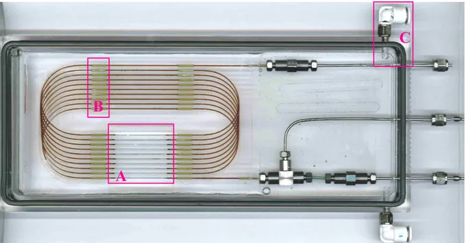
Figure 2: The transparent high pressure micro-reactor – coaxial injection, L = 3 m, ID = 536 µm,
IDinjection = 100 µm
MATERIALS AND METHODS 2.1 Materials and manufacturing step
For our study, a homemade micro-reactor, shown in figure 2, is used. It is based on the capillary microfluidic technology with coaxial injection. It is design to study intermittent (or separated) two-phase flow under a maximum pressure of 20 MPa for the biggest capillary inner diameter used, which is 530 µm.
A poly(methyl methacrylate) (PMMA) block is purchased with dimension of 270 x 140 x 20 mm. PMMA is a thermoplastic easy to machine, with the excellent optical property of transparency. The chassis is then performed in this block using a digital milling machine (Charlyrobot – Charly4U CNR3). Lubrication is required to prevent overheating of the PMMA, that it could cause deformation during machining work. First, the blank (20 mm thickness) is cutting at the micro-reactor dimensions (260 x 110 x 20 mm), and then a square hole is done allowing to etch the polyimide coating (region A in figure 2: this is the area corresponding to the video viewing). Then channels are engraved with 1/16 inch hemispherical diameter – these channels entrap the capillary and the resin
The micro-reactor consists in a cylindrical fused-silica tubing (Polymicro, USA). Tubing is coated with polyimide cladding as a protection and provides a great flexibility to manipulate the capillary without breaking it. This coating has to be removed to have a real transparent observation zone (region A in figure 2). The sleeves adapted to the capillary are plugged on the capillary (region B in figure 2). Their external diameter is 1/16 inch, precisely adapted to plug it into the channels. Thus, the capillary is fixed on the chassis. The two capillary’s extremities stand out in the metal union side. In this state the capillary is ready for the next
A
B
step: etching the coating. Polyimide coating is burnt on the area provided. A delicate cleaning phase is necessary to remove the ash: a fine brush is used allowing the capillary become transparent for video viewing.
Stainless-steel connectors for high pressure applications (Upchurch Scientific, USA) are used to connect the capillary reactor to the external network pipes (pumps etc.). A tee is used to feed the tubular reactor with the continuous phase. Two unions allow connecting with the inlet for the dispersed phase, and with the outlet for the resulting mix.
Epoxy resin (EP 601-LV, Polytec, France) has been selected for its optical properties, its resistance (shear strength 80 N.mm-2) and its fluidity (240 mPa.s). This resin is used for optic applications. An excellent adherence with PMMA has been reported. The microcapillary is then embedded in this resin. The capillary has a maximum inner diameter of 530 µm and an outer diameter of 665 µm. A second capillary is used to inject the dispersed phase with a coaxial configuration. Its inner diameter is 200 µm and the outer one is 350 µm.
Finally the micro-reactor is put into a transparent box and immerged in a circulating heat transfer fluid. The box has been setup to force the fluid circulation everywhere around the micro-reactor. Inlet/outlet for this heat transfer fluid is shown in figure 2 (region C).
2.2 Main advantages
This device presents different advantages.
First, it’s the price: 200 €. The lifetime of micro-reactors is not indefinite. This is highlight when different chemical is applied or when systems work under high pressure. Its lifetime heavily depends on the number of utilisation or more precisely on the number and the way pressure drop/increase are done. That is why its low price allows it to be seen as a disposable device.
This micro-reactor has the further advantage of a circular cross-section compared to the square cross-section presented by on-chip microsystems. In fact, the resulting axial symmetry of the flow has both the advantage to drastically simplify CFD simulation and to allow efficient and reliable measurements with image acquisition.
Another advantage is its resistance. It is even the main objective of this device. It was conceived to resist to pressure up to 20 MPa.
Although, this device doesn't entirely fulfilled one of the main objective: the transparency. Indeed, the epoxy resin combined with the PMMA covering panel absorb almost all radiations in IR and UV regions.
In order to compact their total channel length, the 2D design of on-chip based microdevices presents a very small radius of curvature. Thanks to the 3D design path of our capillary-based micro-reactor, the minimal radius of curvature of the presented configuration is 3 cm and has to be compared to the 100–500 mm radius of curvature of the on-chip 2D design. The curvature effect can lead to flow instabilities or to coalescence of the dispersed phase and can even be used to separate phases. This effect is stronger when the fluids densities difference is
greater, which is true for SC-CO2 - ionic liquid systems, and when the inner diameter is
larger, which is also our case. For this device the Bond number: Bo = ∆! !! !!/! with
!! = !/!!"#$, is calculated with centrifugal acceleration. Considering identical mixtures, with identical operating conditions and with the same channel surface sections, the Bond number of the on-chip microdevices (Rcurv = 0.3 mm) is 100 times higher than of the presented device (Rcurv = 30 mm).
The design strategy presented enables to set up microdevices as long as 3 m. Moreover, the chassis configuration can be easily modified to enable devices of 10 m capillary length or more. This strategy fulfils almost all the criteria required to incorporate a successful macro-to-micro interface design [5].
2.3 Experimental section
Micro-reactor is integrated into a high-pressure circuit, powered by syringe pumps (ISCO 260 ISCO 100 D and HLX) to reach pressure up to 20 MPa in the system. The pumps are filled with [BMIm+][PF6-] (99.9%; Solvionic, France) and with CO2 (purity 99.995%; Linde,
France). Each pump controls the volume flow rates and the two streams feed the micro-reactor, the CO2 being coaxially injected forms the dispersed phase. These pumps as well as
the micro-reactor are temperature controlled. A third syringe pump (ISCO 260 D) placed on the micro-reactor output line serves to maintain and control the output pressure in the system.
After the intermittent two-phase flow being stabilised, the detailed formation of the flow is
registered by a CCD camera (Baumer HXC13) with a resolution of 1280 x 1021 pixels2. The
videos can be acquired at 2000 frames per second. The scene is backlighting with LED lamps
with a total light intensity of 2200 lumen.
RESULTS
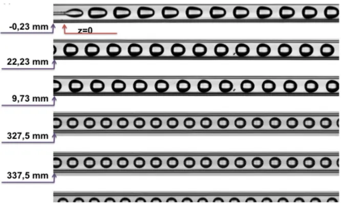
As shown in figure 1 and 3, the CO2 transfers in the continuous phase and the drop size
decreases all along its move in the capillary. The shape of the drop changes and allows to distinguish two regions beyond the generation zone. In the first one convection keeps acting on the transfer of the CO2 and in the second one drops look like sphere and are transport in a
Poiseuille flow, the transfer is only diffusive.
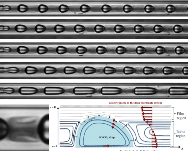
Another observation concerns the presence of a film. The viscous ionic liquid sticks to the inner capillary surface and forms a thick film surrounding a lessviscous tube where the drops circulate faster with a bullet-like shape. It has also been noticed that the film thickness decreases along the capillary as it can be shown in figure 4.
1. The global behaviour change with pressure: At 8MPa CO2 acts as a gas but at 15MPa
it acts as a liquid.
2. When SC-CO2 (supercritical carbon dioxide) is dissolved in [BMIm+][PF6-], the
continuous phase properties considerably change. For example, at 18 MPa and 308 K as the mole fraction of CO2 varies from 0 to 90 %, the density varies from 1400 to
2100 kg.m-3 and the viscosity varies from 0.13 to 0.013 µPa.s. It has been observed that most of the CO2 dissolves in the continuous phase during its move on the first
centimetres. So, in this region the continuous phase splits in two parts: the film which is viscous and moves slowly and the Taylor zone entrapped between two drops formed by an almost saturated phase ten times less viscous, which slips on the film.
3. The film thickness is really large and can be predominant at low CO2 flowrate. 4. The film thickness decreases rapidly and tends to disappear.
In the same way as mentioned properties drastically changed with CO2 dissolution, the
refractive index follow the same trend. So, it has been possible by adapting the backlighting to make visible the toroidal flow in the Taylor zone as it is shown in Figure 5.
Figure 3: Experiment done at P = 9.8 MPa ; T = 318 K ; !̇!"!= 0,09 mL.min-1; !̇
!"#$%&!= 0.11 mL.min -1. Injection position is shown at z = 0 mm.
CONCLUSION
The specific behaviour of a two-phase flow under pressure of a CO2/ionic-liquid system has
been partially explained. It has been possible thanks to a homemade and cheap microdevice. This microdevice was fabricated using capillary microfluidic technology with integrated
connections. An optically-clear epoxy resin was applied on the microdevice in order to
combine optical transparency and mechanical resistance. An experimental high-pressure setup was designed. This setup was implemented to operate and generate stable two-phase flow and to overcome the difficulties due to restricted optical access, pressure adjustment, and temperature control. Thus, this system enables fast process control and detection and is able to produce homogeneous conditions. Consequently, the described microfluidic high-pressure setup is an optimal configuration for a fast study of processes.
In future, this study will permit the applicability of high-pressure operations in a simple microcapillary device. In particular, it will enable to investigate the mass transfer under
pressure of supercritical CO2 in ionic liquids in presence of solutes.
Figure 5: (at the top) Several toroidal shapes of the flow in the Taylor zone between the CO2 drops and their evolution on the first 1 cm. (left) Magnification of a zone. (right) Schema showing flow streamlines and the CO2 transfer magnitude.
REFERENCES
[1] MACEDO PORTELA DA SILVA, N., Doctoral Dissertation, École des Mines d'Albi – INP Toulouse, 28 Mars 2014
[2] MACEDO PORTELA DA SILVA, N., LETOURNEAU, J-J., ESPITALIER, F., PRAT, L., Chemical Engineering & Technology, Vol. 37, 2014, 1929
[3] FRANÇOIS, Y., Doctoral Dissertation, Utilisation de l'électrophorèse capillaire (EC) pour la caractérisation des liquides ioniques (LI) et intérêt des LI comme nouveaux milieux de séparation en EC. Chemical Sciences. Chimie ParisTech, 2006.
[4] ADAMOU, A., LETOURNEAU, J-J., RODIER, E., DAVID, R., & GUIRAUD, P. Properties measurement of the binary ionic liquid BMImPF6/SC-CO2 Part 2: Viscosity, I.S.A.S.F. 8th International Symposium on Supercritical Fluids, 2006, Kyoto, Japan
![Figure 1: Co-axial injection of SC-CO 2 in [BMIm + ][PF 6 - ] continuous phase – P = 11.4 MPa (inlet); T = 318 K;](https://thumb-eu.123doks.com/thumbv2/123doknet/11316788.282467/2.892.109.794.921.990/figure-axial-injection-bmim-continuous-phase-mpa-inlet.webp)