HAL Id: tel-01523792
https://hal.archives-ouvertes.fr/tel-01523792v2
Submitted on 21 Dec 2017HAL is a multi-disciplinary open access
archive for the deposit and dissemination of sci-entific research documents, whether they are pub-lished or not. The documents may come from teaching and research institutions in France or abroad, or from public or private research centers.
L’archive ouverte pluridisciplinaire HAL, est destinée au dépôt et à la diffusion de documents scientifiques de niveau recherche, publiés ou non, émanant des établissements d’enseignement et de recherche français ou étrangers, des laboratoires publics ou privés.
Matthieu Kanj
To cite this version:
Matthieu Kanj. Intelligent supervision of flexible optical networks. Networking and Internet Archi-tecture [cs.NI]. Université Rennes 1, 2016. English. �NNT : 2016REN1S138�. �tel-01523792v2�
THÈSE / UNIVERSITÉ DE RENNES 1
sous le sceau de l’Université Bretagne de Loire
pour le grade de
DOCTEUR DE L’UNIVERSITÉ DE RENNES 1
Mention : Informatique
Ecole doctorale MATISSE
présentée par
Matthieu KANJ
Préparée à l’IRISA (UMR 6074)
Institut de Recherche en Informatique et Système Aléatoires
Equipe Adopnet (Advanced Technologies for Operated Networks)
Intelligent
supervision of
flexible optical
networks
Thèse soutenue à Rennes
le 20 Décembre 2016
devant le jury composé de :
Cédric WARE
Maître de conférences (HDR) à Telecom ParisTech
/ Rapporteur
David COUDERT
Directeur de recherche (HDR) à INRIA Sophia Antipolis / Rapporteur
Ramon CASELLAS
Ingénieur de recherche à CTTC Barcelone /
Examinateur
Jean-Marie BONNIN
Professeur des universités à Telecom Bretagne / Examinateur
Esther LE ROUZIC
Ingénieur de recherche à Orange Labs/
Co-encadrant
Bernard COUSIN
Professeur à Université de Rennes 1 / Directeur de
thèse
Dominique VERCHÈRE
This dissertation would not have been possible without the guidance and the help of several individuals, who in one way or another contributed and extended their va-luable assistance in the preparation and completion of this study.
Firstly and foremost, I would like to thank my supervisor Prof. Bernard Cousin for given me the opportunity to realize my PhD at B-com Technology Research Institute. I am deeply grateful for the advice and support that I have received from him over the past three years.
My most sincere thanks goes to Esther Le Rouzic, who supervised me throughout this thesis and contributed greatly to my training on optical networks. Working with you was an opportunity to learn a lot, and acquire precious knowledge on optical com-munication and R&D. It was a great pleasure to work with a person like you, who is active, full of energy and ideas.
I would especially like to thank Julien Meuric, Jean-Luc Augé and Nicolas Brochier, who provided their expertise to enable this thesis to work well and for their support. The many discussions we have had, has helped me a lot.
I would like to express my sincere thanks to the committee members, David Cou-dert, Cédric Ware, Ramon Casellas, Jean-Marie Bonnin, and Dominique Verchère, for accepting to evaluate this work and to be part of the jury. I am particularly honored that Cedric Ware and David Coudert have agreed to evaluate this dissertation. I am very grateful for their feedback on this work.
I would like to express my deep gratitude and sincere thanks to our team leader Rodolphe Legouable, and our lab chief Stéphane Paquelet, for their support and help during the preparation and the completion of this thesis. I would also like to thank our domain chief Michel Corriou and B-com director Bertrand Guilbaud for the support, the motivation and the excellent working conditions that they offered.
I wish to express my thanks to my colleagues in B-com and Orange Labs : Pape Ab-doulaye FAM, Ali Zeineddine, Antoine Rozé, Hamidreza Khaleghi, Andrey Fedosov, Flo-rian Lebeau, Jean Dion, Pauline Desnos, Vincent Savaux, Patrick Savelli, Imad Alawe, Olivier Weppe, Rémi Bonnefoi, Lilian Delaveau, Pierre Didier, Marc Lanoiselée, Fran-coise Liégeois, Djamel Amar and Ahmed Frikha.
I am very grateful to my family, especially my parents for their patience, motivation and support during these three years.
Finally, the deepest gratitude and heartiest thanks goes to my love Hiba for her continuous help and moral support.
Les réseaux optiques dynamiques et flexibles font partie des scénarios d’évolution des réseaux de transport optique. Ceux-ci formeront la base de la nouvelle génération des réseaux optiques de demain et permettront le déploiement efficace des services tel que le Cloud Computing. Cette évolution est destinée à apporter flexibilité et automa-tisation à la couche optique, mais s’accompagne d’une complexité supplémentaire, notamment au niveau de la gestion et de la commande de cette toute nouvelle généra-tion de réseau.
Jusqu’à récemment, les protocoles de routage et de signalisation normalisés ont pris en compte plusieurs paramètres physiques tels que l’information spectrale de la bande passante, le format de modulation, et la régénération optique. Cependant, d’autres paramètres sont encore nécessaires (par exemple, les puissances optiques des liens, le gain des amplificateurs) afin de faire fonctionner efficacement de grands ré-seaux. Dans ce contexte, il y a un besoin d’étudier les réseaux optiques existants ainsi que les différentes méthodes de prise en compte de la couche photonique dans le plan de contrôle. Le but est d’avoir un réseau optique automatique, flexible et program-mable, mais surtout efficace de point de vue économique et opérationnel.
L’utilisation de la technologie à grille flexible a un impact sur les réseaux optiques existants, où presque tous les équipements devront être remplacés, ce qui entrainera un cout additionnel pour les opérateurs. Dans ce travail, nous étudions les réseaux optiques actuels et évaluons l’impact de la flexibilité sur les infrastructures existantes. Ensuite, nous identifions plusieurs paramètres optiques à contrôler et proposons des extensions protocolaires afin d’intégrer ces paramètres dans un plan de contrôle GM-PLS. De plus, nous développons les algorithmes de routage et de signalisation qui per-mettent la mise en oeuvre d’un plan de contrôle efficace qui répond au besoin de la flexibilité. Enfin, l’ensemble de nos propositions et de nos solutions sont évaluées sur plusieurs topologies réseaux avec des modèles de trafic différents dans le but de valider leur pertinence.
Dynamic and flexible optical networks are among the evolution scenarios of the optical transport networks. These form the basis of the new generation of optical networks of tomorrow and enable the effective deployment of services such as cloud computing. This evolution is intended to provide flexibility and automation to the optical layer. However, it results in additional complexity, particularly in terms of the management and control of this new network generation.
Until recently, the standardized routing and signaling protocols have been taking into account several optical parameters like the spectral bandwidth information, mod-ulation format, and optical regeneration. However, other parameters (e.g., link optical powers, gain of optical amplifiers) are still required in order to efficiently operate large optical networks. In this context, there is a need to study the existing optical networks and the different integration methods of the photonic layer in a control plane. The goal is to get an automatic optical network that is flexible, programmable, and at the same time efficient from an economical and operational perspective.
The use of flexible grid technology has an impact on existing optical networks, where almost all the equipment must be replaced, resulting in an additional cost to network operators. In this work, we study the current optical networks and evaluate the impact of flexibility on the existing infrastructures. Then, we identify several phys-ical parameters to be controlled and propose protocol extensions in order to integrate these parameters in the GMPLS control plane. In addition, we develop the routing and signaling algorithms that allow the implementation of an efficient control plane that addresses the need for flexibility. Finally, the set of our proposals and solutions are evaluated on multiple network topologies with different traffic patterns in order to val-idate their relevance.
Introduction
Les réseaux de transport optiques constituent la base des systèmes de télécommunica-tions d’aujourd’hui. Grace à la grande capacité et la longue portée des fibres optiques qui les constituent, ils sont utilisés pour interconnecter les grandes villes et les pays à internet et aux fournisseurs de services dans le monde entier. La convergence techno-logique vers un plan de données unifié fait que tout le trafic issu de n’importe quelles couches de services (IP / MPLS, Ethernet, DSL, ATM, etc.) est transporté sur les ré-seaux optiques grâce aux systèmes de transmission WDM. Ce rôle crucial des réré-seaux optiques, ainsi que leurs coûts considérables en termes de CAPEX (dépenses en ca-pital) et OPEX (dépenses opérationnelles) explique la forte attention accordée par les opérateurs à ces réseaux, en particulier en termes de performance et de gestion de res-sources.
Au cours des dernières années, nous avons assisté à l’explosion du trafic Internet en raison de la croissance phénoménale des applications d’Internet telles que les vidéos, la HDTV, le trafic de données mobiles, les jeux en ligne, le partage de fichiers, les sites de réseautage social, etc. Cette demande croissante de bande passante est estimée de produire encore une augmentation significative dans les années à venir. Tout cela a stimulé le besoin de réseaux IP à haute vitesse, mais aussi la nécessité d’accroître la ca-pacité des réseaux de transport optiques. Pour faire face à cette tendance, les progrès technologiques en communication optique ont été déclenchés, afin d’obtenir des sys-tèmes de transmission optique efficaces, offrant des débits élevés avec une utilisation efficace de la bande passante. L’objectif est d’évoluer vers des infrastructures de réseau coeur optique flexible et dynamique.
Les réseaux de transport optiques d’aujourd’hui sont construits en utilisant le système de transmission WDM. Plusieurs canaux optiques sont présents au sein de chaque fibre optique. Chaque noeud optique du réseau contient un ensemble de mo-dules WSS (Wavelength Selective Switch) qui permettent de commuter optiquement n’importe quel canal optique. Cependant, ces systèmes WDM sont conçus avec la technologie fixed-grid, avec l’inconvénient de ne pas pouvoir exploiter efficacement les ressources en bande passante optique du réseau : chaque canal optique occupant une bande passante identique et offrant un débit fixe. La nécessité d’une plus grande capacité dans les réseaux optiques stimulée par l’augmentation du trafic a déclenché
de nombreuses avancées technologiques [1], conduisant à l’introduction des techno-logies flex-grid pour la commutation optique. Cette technologie permet une gestion dynamique et efficace des ressources de bande passante disponibles au sein du ré-seau. En effet, les réseaux flex-grid sont attrayants en raison de leur potentiel d’amé-lioration de l’efficacité spectrale d’environ 30%. Ils offrent la possibilité de fournir des canaux de bande passante variable (i.e., plus petit ou plus grand de 50GHz), et per-mettent ainsi le développement futur de transpondeurs à débit binaire supérieur. Ce-pendant, le déploiement des réseaux flex-grid nécessitera beaucoup plus qu’un WSS
flex-grid [1]. Ces réseaux nécessiteront des ROADMs (Reconfigurable optical add/drop multiplexer) flexibles, des transpondeurs conçus pour fonctionner sur une grille ayant
des longueurs d’onde plus étroites, de nouveaux logiciels de gestion du réseau et des outils de planification du réseau plus sophistiqués. De plus, ils devraient être en me-sure de gérer la problématique de la fragmentation de la bande passante qui apparaîtra à cause de l’établissement et de la suppression de canaux optiques ayant des largeurs de bande variables dans un environnement présentant un trafic dynamique.
En général, l’objectif principal d’un opérateur de réseau est d’assurer un équilibre entre la gestion optimale des ressources et la minimisation des coûts associés à l’ex-ploitation du réseau. Les opérateurs sont de plus en plus à la recherche de solutions automatisées pour optimiser le routage et l’allocation des ressources dans la phase opérationnelle. A cet égard, un plan de contrôle intelligent joue un rôle important dans l’évolution des réseaux optiques. Le plan de contrôle permettra d’activer les équipe-ments constituant le réseau optique et de gérer de nouveaux services dynamiques et donc la demande variable de trafic. Il améliore également l’efficacité du réseau et la ré-silience du réseau. Enfin, il aide à réduire les frais d’exploitation en simplifiant la mise en service et la maintenance du réseau, ce qui permet la fourniture rapide de bande passante et d’éviter les processus manuels de configurations complexes et longues.
Le protocole GMPLS (Generalized Multiprotocol Label Switching) est une des im-plémentations possibles du plan de contrôle. Il est bien connu, couramment et majo-ritairement utilisé pour la gestion des réseaux optiques. Il est proposé et développé par l’IETF (Internet Engineering Task Force) en tant qu’un plan de contrôle générique pour les réseaux utilisés pour le provisionnement des chemins de bout-en-bout pour les réseaux des fournisseurs de services Internet et télécoms. Cependant, la norme GM-PLS actuelle ne prend pas en charge toutes les fonctionnalités annoncées par la tech-nologie flex-grid. Pour cela, de nombreuses améliorations doivent être apportées aux protocoles du plan de contrôle GMPLS afin de prendre en compte les phénomènes tels que les dégradations optiques et la fragmentation. De plus, ils devront prendre en compte aussi les mécanismes tels que le routage et affectation du spectre (RSA), l’in-teropérabilité entre les fournisseurs d’accès internet, et la virtualisation des services de transport.
Dans ce contexte difficile, cette thèse vise à améliorer les fonctionnalités de gestion du plan de contrôle GMPLS afin de faciliter l’intégration de la technologie flex-grid dans les réseaux optiques actuels. Le travail réalisé est divisé en deux parties princi-pales. La première partie se concentre sur les conséquences de la migration vers un
réseau flex-grid sur la couche optique. Plus précisément, nous nous concentrons sur le niveau de puissance des amplificateurs optiques et nous proposons une solution au problème d’intégration de la flexibilité sur les infrastructures existantes des réseaux optiques fixed-grid. La deuxième partie se concentre davantage sur les aspects du plan de contrôle où des améliorations et de nouvelles extensions protocolaires sont propo-sées pour inclure les paramètres optiques identifiés dans le plan de contrôle GMPLS. Des nouveaux algorithmes de routage et de mécanismes de signalisation sont dévelop-pés dans le cas des réseaux optiques transparents et translucides.
Contributions
La croissance exponentielle du trafic dans les réseaux optiques a déclenché l’évolu-tion vers des réseaux optiques flexibles, promettant un gain significatif pour les opé-rateurs de réseau en termes d’efficacité spectrale sur leurs infrastructures de réseau optique. Cependant, le déploiement de nouveaux liens optiques et le remplacement des équipements optiques existants rendent la technologie flexible très coûteuse pour les opérateurs des réseaux malgré ses promesses de capacité accrue. Dans ce contexte, les opérateurs de réseaux tentent de réduire les coûts (c’est-à-dire les coûts d’achat et d’exploitation) de la migration vers les réseaux flexibles en maintenant l’utilisation de leurs infrastructures existantes.
Dans ce travail de thèse, nous avons abordé la technologie flexible et ses impacts sur le plan de données et le plan de contrôle des réseaux de transport optiques actuels. Nous nous sommes concentrés sur le problème de la saturation de la puissance qui pourrait éventuellement être rencontré lors de la migration des réseaux optiques
fixed-grid vers les réseaux optiques flex-fixed-grid lorsqu’on tente de conserver les infrastructures
optiques actuelles. En particulier, nous avons abordé le problème qui n’a jamais été étudié précédemment, concernant la saturation de puissance dans les amplificateurs optiques due à l’augmentation du nombre de canaux optiques établis.
L’objectif principal de notre travail était, d’une part, d’évaluer ce problème de sa-turation de puissance et de proposer une solution qui puisse être facilement implé-mentée dans un plan de contrôle optique. D’autre part, démontrer que l’amélioration de l’intelligence du plan de contrôle permet d’optimiser les ressources du réseau et de bénéficier ainsi de l’augmentation de capacité offerte par la technologie flexible tout en conservant les infrastructures optiques existantes.
C’est dans ce contexte que le travail a été réalisé, les contributions et les résultats sont résumés comme suit :
• Nous avons d’abord introduit au chapitre 1, l’évolution des réseaux optiques en distinguant le plan de données et le plan de contrôle car ils constituent les deux parties principales d’un réseau optique automatisé. Nous avons présenté la phase de conception du réseau et les éléments physiques qui peuvent avoir un impact sur la conception et le contrôle des réseaux optiques. Enfin, nous nous sommes concentrés sur la suite de protocoles de contrôle, GMPLS, largement
utilisée et nous avons fourni une description fonctionnelle de ses protocoles de routage et de signalisation.
• L’évolution vers des réseaux flexibles et l’impact de la flexibilité sur le plan de données et le plan de contrôle des réseaux optiques actuels sont présentés au chapitre 2. Nous avons montré comment les changements dans le plan de don-nées rendus nécessaires par l’ajout d’équipements optiques flexibles peuvent augmenter la complexité de l’algorithme de routage, et donc ils nécessiteront une amélioration des protocoles du plan de contrôle de tout réseau optique automatisé. Ensuite, nous avons présenté les travaux existants dans la littéra-ture qui traitent de la flexibilité, démontrant que l’évolution vers des réseaux flexibles automatisés permet d’optimiser les ressources et d’augmenter la capa-cité des réseaux optiques actuels. Enfin, nous avons souligné que l’augmentation du nombre de canaux offerts par la technologie flexible peut augmenter le niveau de puissance optique dans les liens optiques, soulevant l’importance de prendre en compte la puissance optique comme une limitation lors de la migration vers un réseau flexible.
• Dans le chapitre 3, nous avons abordé le problème de saturation de puissance qui pourrait apparaitre après la migration du réseau fixed-grid vers le réseau
flex-grid lorsque l’on maintient en service les infrastructures optiques existantes.
Nous nous sommes concentrés tout d’abord dans ce chapitre, sur les réseaux op-tiques transparents avec un modèle de trafic incrémental, pour simuler le cas du réseau statique. Le problème de saturation de puissance a été abordé comme suit : Tout d’abord, nous avons développé une méthode de conception de liens optiques qui nous a permis de déterminer le niveau de puissance sur les liens du réseau. Ensuite, nous avons identifié les paramètres essentiels requis par un plan de contrôle optique pour contrôler et évaluer ces niveaux de puissance. Deuxiè-mement, nous avons proposé un processus d’adaptation de puissance par ca-nal qui bénéficie des marges de transmission pour réduire la puissance trans-mise des canaux optiques. Finalement, nous avons proposé un algorithme de calcul de chemin, avec des extensions protocolaires pour les protocoles de rou-tage et de signalisation de la suite protocolaires GMPLS, afin de fournir la mise en oeuvre pratique d’un tel processus d’adaptation de puissance. Les résultats de la simulation ont démontrés que les niveaux de puissance de l’infrastructure
fixed-grid ne sont pas suffisants pour permettre l’augmentation du nombre de
canaux optiques lors de la migration vers un réseau flex-grid. Ils ont également montré que l’utilisation du processus d’adaptation de puissance permet de ré-duire le problème de saturation de puissance et donc d’augmenter la capacité du réseau. Enfin, ils ont démontré aussi que l’augmentation du nombre des plus courts chemins calculés ne permet pas d’éviter complètement le problème de saturation, même si le processus d’adaptation de puissance est utilisé.
translu-cides (donc avec régénération) sous un modèle de trafic dynamique, pour si-muler le cas des futurs réseaux optiques automatiques et flexibles. Le processus d’adaptation de puissance et l’algorithme de calcul de chemins ont été adap-tés au cas des canaux optiques régénérés. Ensuite, nous avons proposé de nou-velles extensions aux protocoles de routage et de signalisation pour permettre la gestion de la régénération optique et l’adaptation de puissance. Les résultats de la simulation ont montré que le problème de saturation de puissance se pose même à une faible charge du réseau et sous des modèles de trafic dynamique. En plus, comme dans le chapitre 3, l’augmentation de la capacité du réseau ne peut pas être exploitée si le processus d’adaptation de puissance n’est pas utilisé dans les scénarios flexibles. Il a été montré également que la méthode de régéné-ration utilisée dans l’algorithme de calcul de chemins peut impacter les perfor-mances et le coût du réseau. Pour aller plus loin, nous avons répété les simula-tions sur des topologies de réseau supplémentaires. Les résultats ont montré une forte dépendance entre la topologie du réseau et l’apparition du problème de sa-turation de puissance. Les topologies possédant des liens optiques introduisant une faible dégradation du signal auront probablement des marges de puissance suffisantes pour éviter le problème de saturation de puissance et pourront sup-porter les canaux flexibles supplémentaires lorsque le processus d’adaptation de puissance sera utilisé.
• Dans le chapitre 5, nous nous sommes intéressés au problème persistant de sa-turation de puissance dans les réseaux optiques translucides flexibles. Par consé-quent, nous avons proposé un nouvel algorithme de régénération qui utilise les informations de puissance des liens du réseau pour sélectionner les sites de ré-génération. L’algorithme a été appliqué dans les scénarios flexibles en utilisant le processus d’adaptation de puissance, où le problème de saturation se pose en-core. Les résultats de simulation ont montré que l’algorithme réussit à éviter le problème de saturation de puissance en modifiant la répartition de puissance sur les liens du réseau. Cependant, la performance de l’algorithme a montré une dépendance vis-à-vis de la topologie du réseau.
Conclusion
Ce travail a mis en évidence l’importance de prendre en compte l’information de puis-sance des liens optiques lors de la migration vers les réseaux flex-grid. Il a permis de comprendre l’impact des niveaux de puissance des liens optiques sur le gain de capa-cité attendu de la technologie flexible. De plus, ce travail a permis de développer les extensions protocolaires et les algorithmes de calcul de chemins nécessaires pour réa-liser l’implémentation de l’adaptation de la puissance par canal dans les futurs réseaux optiques flexibles.
Acknowledgements i
Résumé iii
Abstract v
Résumé étendu en français vii
Contents xiii
List of acronyms xvii
Notations xix
List of Figures xx
List of Tables xxiii
Introduction 1
1 Optical network 5
1.1 The optical transport networks: evolutions and problematic . . . 5
1.1.1 Opaque mode . . . 7 1.1.2 Transparent mode . . . 7 1.1.3 Translucent mode . . . 8 1.2 Optical impairments . . . 9 1.2.1 Linear impairments . . . 9 1.2.1.1 Power attenuation . . . 9
1.2.1.2 Amplifier Spontaneous Emission (ASE) . . . 10
1.2.1.3 Polarization Dependent Loss (PDL) . . . 10
1.2.1.4 Chromatic Dispersion (CD) . . . 10
1.2.1.5 Polarization Mode Dispersion (PMD) . . . 11
1.2.1.6 Linear Crosstalk (CT) . . . 11
1.2.1.7 Filter concatenation . . . 11
1.2.2 Non-linear Impairments (NLIs) . . . 11 xiii
1.3 Link design and impairment awareness . . . 12
1.3.1 Link design and impairment modeling . . . 12
1.3.2 Existing impairment estimators . . . 14
1.3.3 Impairments models accuracy . . . 15
1.4 Optical control plane . . . 15
1.4.1 Role of the control plane . . . 16
1.4.1.1 Call and connection control . . . 17
1.4.1.2 Discovery . . . 17
1.4.1.3 Routing . . . 17
1.4.1.4 Path computation . . . 18
1.4.1.5 Signaling . . . 18
1.4.2 Routing and wavelength assignment problem in optical networks 18 1.4.2.1 Offline RWA and network dimensioning . . . 19
1.4.2.2 Online RWA . . . 19
1.5 Existing protocol implementations of the control plane . . . 20
1.6 GMPLS control plane . . . 21
1.6.1 GMPLS . . . 21
1.6.2 OSPF-TE . . . 21
1.6.3 RSVP-TE . . . 23
1.6.4 LMP . . . 23
1.6.5 Path computation and protocol extension in GMPLS control plane 23 1.7 Tendencies in optical networking . . . 24
1.8 Conclusion . . . 25
2 Flexibility in optical network 27 2.1 Optical network components . . . 27
2.1.1 Optical transceiver . . . 28
2.1.2 ROADM . . . 28
2.1.3 Optical amplifier . . . 28
2.1.4 Optical fiber . . . 29
2.2 Flexibility impact on the optical layer . . . 30
2.2.1 Flexible optical switches . . . 30
2.2.2 Flexible transceivers . . . 31
2.2.3 Flexible frequency grid . . . 31
2.3 Flexibility impact on the control plane . . . 33
2.3.1 Impact on path computation and impairment estimation . . . 33
2.3.1.1 RWA vs RSA . . . 33
2.3.1.2 Spectrum fragmentation problem and spectrum as-signment policy . . . 33
2.3.1.3 Physical feasibility of optical channels . . . 35
2.3.2 Impact on GMPLS control plane protocols . . . 36
2.4 Network margins and resources optimization . . . 37
2.4.1.1 System margins . . . 37
2.4.1.2 Unallocated margins . . . 37
2.4.1.3 Design margins . . . 38
2.4.2 Resources optimization . . . 38
2.5 Conclusion and motivations . . . 39
3 Optical power control in GMPLS control plane 41 3.1 Related works . . . 42
3.2 Contributions . . . 43
3.3 Optical link design and power limitations . . . 44
3.3.1 Design method . . . 45
3.3.2 Link power margin . . . 47
3.4 Optical power control . . . 49
3.5 Routing algorithm . . . 50
3.6 GMPLS protocol extensions . . . 53
3.6.1 OSPF-TE extensions . . . 53
3.6.2 RSVP-TE extensions . . . 54
3.6.3 Connection establishment example . . . 55
3.7 Simulation scenarios and results . . . 58
3.7.1 Simulation setup and scenarios . . . 58
3.7.2 Simulation results . . . 61
3.7.3 Blocking reasons . . . 65
3.7.3.1 One shortest path . . . 66
3.7.3.2 Three shortest paths . . . 70
3.8 Conclusion . . . 72
4 Optical power control with regeneration 73 4.1 State of the art . . . 74
4.2 Contributions . . . 75
4.3 Optical power control with regeneration . . . 76
4.3.1 Optical regeneration assignment method . . . 76
4.3.2 Power adaptation with optical regeneration . . . 77
4.4 Routing algorithm with regeneration . . . 77
4.5 GMPLS protocol extensions with regeneration . . . 79
4.5.1 OSPF-TE . . . 80
4.5.2 RSVP-TE extensions . . . 81
4.5.2.1 Label encoding . . . 81
4.5.2.2 Extension for Cad apt at i on . . . 82
4.5.2.3 Regeneration encoding . . . 82
4.5.3 Connection establishment example . . . 82
4.6 Simulation and results . . . 85
4.6.1 Simulation setup and scenarios . . . 85
4.6.3 Simulation results . . . 89
4.6.4 Blocking reasons analysis . . . 91
4.6.5 Performance in terms of optical regeneration . . . 93
4.6.6 Other networks topologies . . . 96
4.6.6.1 NSF topology . . . 97
4.6.6.2 German topology . . . 100
4.7 Conclusion . . . 104
5 Power aware regeneration algorithm 105 5.1 State of the art . . . 105
5.2 Formalization of algorithm objective . . . 107
5.3 Power aware regeneration algorithm . . . 109
5.3.1 PAR algorithm execution example . . . 110
5.3.2 Functional description . . . 112
5.4 Simulation and results . . . 114
5.4.1 Blocking probability and blocking reasons . . . 116
5.4.2 Evaluation in terms of power levels . . . 118
5.4.3 Evaluation in terms of optical regeneration . . . 119
5.4.4 Simulations with other topologies . . . 121
5.5 Conclusion . . . 122
Conclusions and prospects 125
ASE Amplifier Spontaneous Emission
BER Bit Error Rate
BP Blocking Probability
CAPEX Capital Expenditure
CBR cumulative blocking ratio
CT Crosstalk
CD Chromatic Dispersion
DCF dispersion compensation fiber
DCM dispersion compensating module
DSP digital signal processing
EDFA Erbium doped fiber amplifier
EDWA Erbium doped waveguide amplifier
ERO Explicit Route Object
FEC Forward Error Correction
FWM four-wave mixing
GMPLS Generalized Multiprotocol Label Switching
IETF Internet Engineering Task Force
ILP Integer Linear Programing
IM Inverse Multiplexing
ITU-T International Telecommunication Union Telecommunication
LCoS liquid Crystal on Silicon
LMP Link Management Protocol
LSA Link State Advertisement
LSDB Link States Database
LSP Label Switch Path
MEMS Micro-Electro Mechanical System
MIB Management Information Base
MTOSI Multi-Technology Operations System Interface
MXCE Maximum channel number exceeded
NETCONF Network Configuration Protocol
NF Noise Figure
NFV Network Functions Virtualization
NLI Non-linear Impairment
OEO Optical-to-Electrical-to-Optical
ONF Open Networking Foundation
OPEX Operational Expenditure
OSPF-TE Open Shortest Path First with Traffic Engineering extensions
OXCs Optical Cross Connects
OSNR Optical Signal to Noise Ratio
PA Power Adaptation
PAR Power Aware Regeneration
PCE Path Computation Element
PDH Plesiochronous Digital Hierarchy
PDL Polarization Dependent Loss
PMD Polarization Mode Dispersion
PSD Power Spectral Density
PV Power Verification
QPSK Quadrature Phase-Shift Keying
RF Regenerator Flag
RAO Regenerator Availability Object
RO Regenerator Object
ROADM Reconfigurable Optical Add/Drop Multiplexer
RSA Routing and Spectrum Assignment
RSVP Resource Reservation Protocol
RWA Routing and Wavelength Assignment
SBS Stimulated Brillouin Scattering
SDH Synchronous Digital Hierarchy
SDN Software Defined Networking
SNMP Simple Network Management Protocol
SNR Signal to Noise Ratio
SOA Semiconductor Optical Amplifier
SPM self-phase modulation
SRS Stimulated Raman Scattering
TE Traffic Engineering
TED Traffic Engineering Database
TLV Type-Length-Value
UNI User Network Interface
WDM Wavelength Division Multiplexing
WSS Wavelength Selective Switch
α Fiber attenuation coefficient ℵl Set of amplifiers of the link l
an Attenuation of the nt hspan
Cad ap t at i on Channel power attenuation value
Gn Gain of the nt hamplifier
GO A_max Maximum amplifier gain
k Index of the optical path
K Number of shortest paths
L Optical fiber length
l Index of the optical link
N Number of network nodes
Nchannel _max Maximum number of channels per link
Nchannel _max,l Maximum number of channels of the link l
N F Noise figure
OSN Rest ,p Estimated OSNR for the path p
OSN Rmar g i n,p Difference between the estimated and required OSNR for the path p
OSN Rr eq,p Required OSNR for the path p
p Optical path
Pd esi g n,l The optical power designed for the link l
Pi n Input optical power
Pl(t ) Current optical power over the link l at time t
Pmar g i n,l Optical power margin over the link l
Pmax,l Maximum optical power allowed at the input of the link l
Pn Input optical power of the nt hspan
PO A_mar g i n,n Optical power margin over the nt hamplifier
PO A_max Amplifier maximum output power
PO A_max,n Maximum output power of the nt hamplifier
Pchannel ,lopt Channel optimum power over link l
Pchannel ,popt Channel optimum power over the path p
Pchannel ,pad apt ed Channel optical power after power adaptation over the path p
Pout Output power
S Number of spectrum slots
t Time
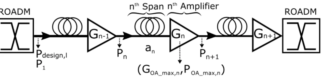
1.1 Operator networks hierarchy . . . 6 1.2 Set of optical spans and amplifiers constituting an optical link between two
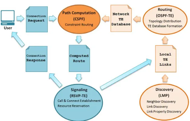
ROADMs. . . 12 1.3 Gain variation versus the NF for a set of three optical amplifiers. . . 13 1.4 Simplified representation of the data and control plane in optical networks. . 16 1.5 Simplified representation of the interactions between GMPLS control plane
protocols. . . 22 2.1 Example of ROADM architecture . . . 29 2.2 Fixed-grid versus flex-grid . . . 32 2.3 Example of horizontal and vertical spectrum fragmentation . . . 34 2.4 Margins and their evolution in a transport optical network [2] . . . 38 3.1 Channel OSNR versus channel power . . . 42 3.2 Simplified representation of an amplified link (succession of a fiber span
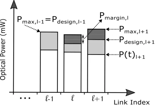
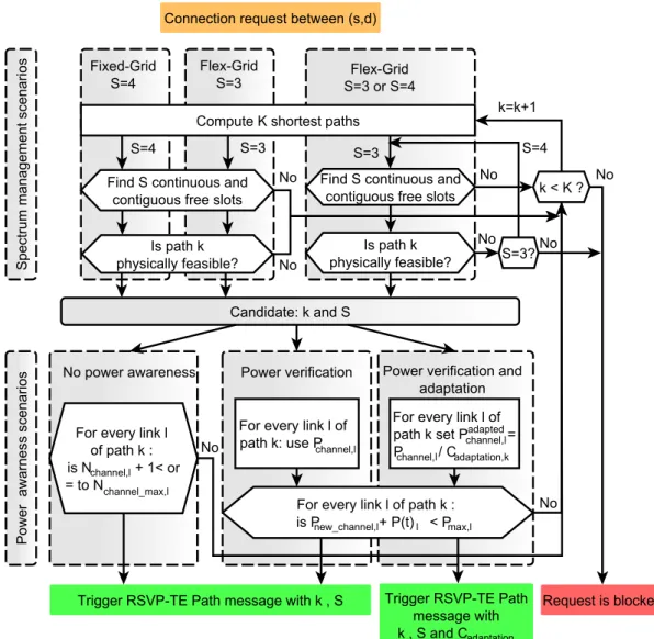
and optical amplifier) between two ROADMs. . . 44 3.3 A simplified representation of optical power at amplifier level. . . 48 3.4 Simplified representation of power levels over optical links. . . 48 3.5 Optical channels with and without power adaptation. . . 51 3.6 Path Computation Algorithm. . . 52 3.7 Network example. . . 56 3.8 Flow diagram in A, B, and C controller during the connection provisioning
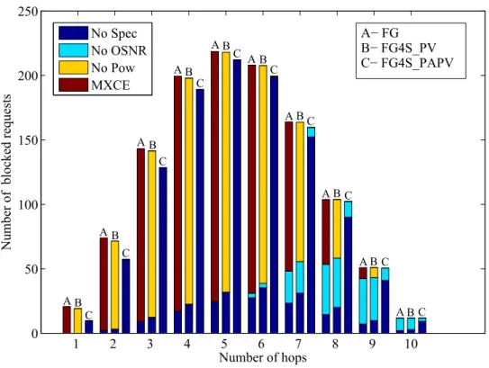
process. . . 57 3.9 European Backbone Network Topology. . . 58 3.10 Path computation algorithm of the simulated scenarios. . . 61 3.11 Cumulative blocking ratio vs. normalized spectrum occupation. . . 62 3.12 Network throughput vs. normalized spectrum occupation. . . 64 3.13 Blocking reasons in FG scenarios. . . 66 3.14 Blocking reasons per number of hops in FG scenarios. . . 67 3.15 Blocking reasons in FX scenarios. . . 68 3.16 Blocking reasons per number of hops in FX scenarios. . . 69 3.17 Blocking reasons per number of hops in FG scenarios with K=3. . . 70 3.18 Blocking reasons per number of hops in FX scenarios with K=3. . . 71
4.1 Example of an unfeasible optical path . . . 76 4.2 Regeneration assignment using the default regeneration algorithm . . . 77 4.3 Path computation algorithm with regeneration . . . 78 4.4 Network example . . . 83 4.5 Flow diagram in F, A, B, and C controller during the connection provisioning
process. . . 84 4.6 Blocking probability versus Network load . . . 89 4.7 Blocking reasons per simulated scenario . . . 92 4.8 Number of regenerators used per scenario as a function of network load . . . 93 4.9 Blocked requests as a function of the number of hops . . . 94 4.10 Blocked requests as a function of the number of hops . . . 95 4.11 Blocked requests as a function of the number of hops . . . 96 4.12 NSF network . . . 97 4.13 German network . . . 98 4.14 Blocking probability as a function of network load in the NSF network . . . . 99 4.15 Blocking reasons per simulated scenario in NSF network . . . 99 4.16 Blocked requests as a function of the number of hops in NSF network . . . . 100 4.17 Number of regenerators used per scenario as a function of network load for
NSF network . . . 101 4.18 Blocking probability as a function of network load in the German network . . 101 4.19 Blocking reasons per simulated scenario in German network . . . 102 4.20 Blocked requests as a function of the number of hops in German network . . 102 4.21 Number of regenerators used per scenario as a function of network load for
German network . . . 103 5.1 Set of optical sub-paths for the K shortest paths between A and C . . . 107 5.2 Regeneration sites assignment result using the default algorithm . . . 110 5.3 Regeneration sites assignment result using the default algorithm . . . 111 5.4 Regeneration sites assignment result using the PAR algorithm . . . 111 5.5 Regeneration sites assignment result using the default algorithm . . . 112 5.6 European backbone network with indexed links . . . 116 5.7 Blocking probability versus Network load . . . 117 5.8 Blocking reasons per simulated scenarios . . . 117 5.9 Percentage of the remaining optical power per link . . . 118 5.10 Normalized spectrum occupation over network links . . . 119 5.11 Percentage of gained power over each link after the use of the PAR algorithm 119 5.12 Number of regenerator used per scenario as a function of network load . . . 120 5.13 Number of regenerators used per node in each simulated scenario . . . 120 5.14 Blocking probability versus network load in NSF network . . . 121 5.15 Blocking reasons per simulated scenarios . . . 122
3.1 Amplifier Models . . . 59 3.2 Simulated scenarios . . . 60 4.1 Simulated Scenarios . . . 88 4.2 Characteristics of German, European and NSF networks . . . 97 5.1 set of input data and variables . . . 108 5.2 Input data for the PAR_Upstream algorithm . . . 113
O
PTICALtransport networks constitute the backbone of today telecommunicationssystems. Thanks to their high capacity and long reach, they are used to inter-connect the major cities and countries to internet and service providers around the world. The technological convergence towards a unified data plane makes that all traf-fic from a variety of service layers (IP/MPLS, Ethernet, DSL, ATM, etc.) is carried over optical networks thanks to Wavelength division multiplexing (WDM) transmission sys-tems. This critical role of optical networks as well as their considerable costs in terms of CAPEX (Capital Expenditure) and OPEX (Operational Expenditure) explains the high attention given by operators to such networks, especially in terms of performance and resource management.
In the recent past years, we have witnessed the explosion of internet traffic due to the phenomenal growth of Internet applications such as videos, HDTV, mobile data traffic, online gaming, file sharing, social networking sites, cloud services, etc. This growth in demand for bandwidth is estimated to still provide a significant increase in the coming years. All this has stimulated the need for high speed IP networks but also the need to increase the capacity of optical transport networks. To cope with this trend, technological advances in optical communication have been triggered in order to get efficient optical transmission systems offering high data rates with efficient bandwidth utilization. The goal is to evolve to a more flexible and dynamic optical core network infrastructures.
Today’s optical transport networks are built using WDM transmission systems. Ev-ery link fiber supports several optical channels (one on each available wavelength). Every optical node in the network contains a set of Wavelength Selective Switch (WSS) modules that allow to optically switching any optical channel. However, these WDM systems are designed with fixed-grid technology; with the disadvantage of not being able to effectively exploit the optical bandwidth resources of the network. The need for more capacity in optical networks driven by the traffic increase has triggered many technological advances [1] leading to introduction of the flexible grid technologies for optical switching. This technology allows the dynamic and efficient management of the available bandwidth resources of the network. Indeed, flexible-grid networks are attractive because of their potential to improve spectral efficiency by approximately 30% [3]. They give the possibility to provision channels with greater than 50 GHz of bandwidth enabling the future deployment of higher bit-rate transponders.
ever, the deployment of flexible-grid networks will require far more than flexible grid WSS [1]. Such networks will require flexible grid reconfigurable optical add/drop multi-plexer (ROADMs), transponders designed to operate over a finer wavelength grid, new management software, and more sophisticated planning tools. Moreover, they should be able to manage bandwidth fragmentation problematic that will appear due to the setup and teardown of mixed sizes of bandwidths in a dynamic network environment. In general, the major objective of an operator is to ensure a balance between op-timal management of resources and minimization of costs associated with the opera-tion of the network. Operators are increasingly looking for more automated soluopera-tions to optimize routing and allocation of resources in operational phase. In this respect, an intelligent control plane plays an important role with the evolution of optical networks. A control plane enables the optical network to support and manage new, dynamic services and traffic demands. It also improves network efficiency and resiliency when applied for dynamic service restoration. Finally, it helps reducing operating expenses by simplifying service turn-up and network maintenance, allowing quickly bandwidth provision and automating complex configuration processes.
The Generalized Multiprotocol Label Switching (GMPLS) protocol is one of the well-known and commonly adopted control plane used for managing optical net-works. It is proposed and developed by the Internet Engineering Task Force (IETF) as a generic network control plane framework. It is used for end-to-end lightpath provi-sioning and core tunneling technologies of the Internet and telecom service providers. However, the current GMPLS standards do not support yet all features announced by flexible grid technology. Therefore, many improvements should be made to the GMPLS control plane protocols in order to support mechanisms such as impairment aware-ness, routing and spectrum assignments (RSA), spectrum defragmentation, multi-vendors and multi-layer interoperability, and network services virtualization.
In this challenging context, this thesis aims to improve GMPLS control plane man-agement functionalities in order to facilitate the integration of flex-grid technology in current optical networks. The realized work is divided into two main parts: the first part focus on the physical layer consequences when migrating to flexible grid network. More specifically, we focus on the power level of optical amplifiers and propose a solution to the flexibility integration problem over the existing fixed-grid network infrastructures. The second part focuses more on control plane aspects where enhancements and new protocol extensions are proposed to include the identified optical parameters in a GMPLS control plane. New routing algorithms and signaling mechanisms are developed for the case of transparent and translucent optical net-works.
The thesis work is organized as follows:
Chapter 1 presents the background knowledge that is used in this thesis. Firstly, it
gives a description of optical networks evolution and describes the physical impair-ments affecting the optical signal during its propagation in the network. Then, it
high-lights the relation between optical link design, impairments estimation and the opti-cal control plane. Secondly, it presents briefly the basic functionalities of an optiopti-cal control plane and detailed the routing and wavelength assignment problem in optical networking. Finally, some of the existing control plane protocols are presented with a focalization on the GMPLS-based protocol suite functionalities.
Chapter 2 is dedicated to the state of the art of the flexible grid technology and to
its impact on the optical and control plane of optical networks. The first part, presents some hardware aspect on optical switching and the improvements realized to the opti-cal plane to improve its flexibility. The second part is dedicated to the impact of flexibil-ity on the control plane and how it affects path computation, impairment estimation and GMPLS control plane protocols. The last part presents some of the recent studies on flexibility and resources optimization in flexible optical networks. Then, it intro-duces the problematic and the motivations of this thesis.
Chapter 3 presents the problem that could be faced when migrating from fixed
grid to flexible grid networks. More specifically, the power saturation problem at opti-cal amplifiers level when keeping in uses the already deployed optiopti-cal links (i.e., optiopti-cal fibers and amplifiers). A power adaptation method is proposed to avoid this power sat-uration. Moreover, protocol extensions, routing algorithm and signaling mechanism are also proposed for transparent optical networks.
In Chapter 4, the case of the translucent optical network is considered, where a state of the art on the existing protocol extensions and signaling mechanisms that deals with optical regeneration is first presented. Secondly, protocols extensions, routing al-gorithm and signaling mechanisms are proposed to implement the power adaptation process in the case of optical regeneration. Finally, the power saturation problem and the power adaptation process are evaluated over different network topologies.
Chapter 5 focuses on the power saturation problem over highly loaded links, where
the power adaptation process was not sufficient to resolve saturation problem. There-fore, a power aware regeneration algorithm is proposed in order to reduce the power level over highly loaded link and thus avoiding power saturation.
Finally, this work is summarized by providing conclusions and perspectives that arise from this study.
C
H A P T1
O
PTICAL NETWORK
T
HIS chapter aims to present the background of this thesis. It offers a generalde-scription of the data and control planes of the automated optical networks. In the first part, the data plane aspects such as the evolution of the optical networks, the op-tical impairments, the link design and the estimation of impairments are presented. They allow understanding the importance of optical impairments and network design phase, on the determination of the optical resources and on the performance of any optical network. In the second part, the role and the objectives of the optical control plane are presented, with a focus on the GMPLS protocol suite that will be used in this work.
These two parts will help understanding how an automated optical network works. The flexibility aspects in optical networks and its impact on the data and control planes are left to the Chapter 2.
1.1 The optical transport networks: evolutions and
problematic
One of the main trends of our time is the growing bandwidth demands of business and carrier networks, due primarily to new uses related to Internet (multimedia services, electronic commerce, etc.) [4]. This change was accompanied by a profound techno-logical transformation of transport networks in order to carry the ever-growing traffic volumes.
The optical fiber is a part of these trends and brings significant improvements in terms of rates, reaches, but not only. It is more reliable, more efficient and has a lower cost and more returns on investment compared to copper cables. However, new prob-lems arise, especially in terms of routing. Indeed, the control of photons circulating in
the optical fiber is not an easy task as the electrical signal processing in copper net-works. Therefore, optical-electrical conversion solutions have been implemented. The optical signals are converted into electrical signals with a transceiver to be processed by upper layers, while optical nodes based on Reconfigurable Optical Add/Drop Multi-plexer (ROADM) steer the optical signals on the optical fibers. This approach takes the advantage of the high capacity of the optical layer.
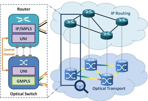
The transport networks have evolved through three main steps: asynchronous networks PDH (Plesiochronous Digital Hierachy), SDH synchronous networks (Syn-chronous Digital Hierarchy) and Optical transport networks (OTN) for the rates beyond 10 Gbits/s. These networks were originally used to transport the traffic of operators (e.g., IP/MPLS flows, ATM, Ethernet, xDSL). The OTN layer uses the optical fibers to en-sure a converging transport layer, integrating all functions usually performed by higher layers and encapsulating all their traffic. The OTN transport layer allows the multiplex-ing, routmultiplex-ing, management and supervision of optical channels carrying client data in the network. The traffic transported by the OTN layer is usually sent over WDM (Wave-length Division Multiplexing) optical networks when the distances exceed few tens of kilometers. In Figure 1.1, we show a network architecture where the packet backhaul traffic in the metro segment and the IP traffic in the core segment of the network are transported by the WDM layer. In this architecture the OTN is a network standard that only serves as encapsulation of the traffic (there is no OTN switching equipment). In this work, we are interested only in WDM optical networks (Figure 1.1) and we do not take into account the possible grooming in OTN sub-layer.
Figure 1.1: Operator networks hierarchy
allow transporting simultaneously a high number of wavelengths (i.e., optical chan-nels) per fiber. This transmission technique allows better utilization of fiber band-width, thereby reducing costs and making best usage of the existing network infras-tructures. Optical transport network based on WDM can operate in three different transport modes, depending on the resort to optical-to-electrical-to-optical (OEO) conversions. These modes are known as opaque, transparent and translucent [5]. In the following, we briefly describe the main characteristics of them.
1.1.1 Opaque mode
In this mode optical-electrical conversions are systematically performed when cross-ing any node. Opaque mode uses point-to-point connectivity, which means that all optical channels between any source and destination node are OEO converted at each intermediate node. This conversion enables the different services to be aggregated ac-cording to their needs at each node. The reception and retransmission of the optical signal in each crossed node is called ”signal regeneration”, which means that all im-pairments accumulated before the OEO conversion are cancelled.
In fact, optical signals are degraded when propagating in the optical fibers due to physical impairments. The advantage of this mode is that it eliminates the cascading of physical impairments (i.e., optical impairments) and allows services to be flexibly steered on any route without any limit of distance. Moreover, the OEO conversion al-lows benefiting from the aggregation and disaggregation of traffic in the electrical layer to better fill the optical channels. However, this mode increases the cost of the network when a large amount of traffic transits in nodes without the need to be groomed (i.e., grooming is not required): the systematic OEO conversion in this case is not required and could be saved by bypassing the nodes. This drives us to the second mode: trans-parent mode.
1.1.2 Transparent mode
In order to reduce the cost of optical transport network by eliminating the OEO con-versions, new concepts of nodes have emerged [6, 7]. ROADMs are the best example of this kind of photonic nodes. This type of node is capable of switching in optical domain an optical signal arriving from an input fiber to another output fiber without necessar-ily undergoing an OEO conversion, giving the possibility to have transparent optical networks.
In transparent optical networks, all optical connections between a source and a destination node are optically switched when passing through intermediate nodes. The OE and EO conversions are only present at the source and destination nodes in order to allow the insertion and extraction of the signal (i.e., data packets) from the optical network. The advantages of such networks are in terms of cost and power con-sumption since no longer OEO conversions are performed in intermediate nodes. It is
thus a viable choice for small-scale networks with short diameter and limited number of nodes.
However, it is not likely to be a practical solution for large scale networks for the following reasons:
• Physical impairments: the optical signal propagation in optical fiber undergoes physical degradation that depends on several aspects, like the characteristics of fiber and optical amplifiers. This limits the reach of optical signals, especially when crossing a high number of optical links and nodes.
• The continuity of wavelength: In transparent networks, the chosen wavelength at the transmitter side cannot be changed in transit nodes, because the resort to intermediate OEO devices is forbidden1. Therefore, the same wavelength is used over all crossed optical links.
It is not easy to choose between opaque and transparent networks. An opaque net-work appears easier to manage and to optimize; but this simplicity comes at the ex-pense of the number of resources consumed. A transparent network gives the possi-bility to reduce OEO conversion. However, this creates complexity due to the physical impairments and wavelength continuity. Therefore, in order to resolve transparency problems while keeping its advantages, another network concept is privileged: translu-cent network.
1.1.3 Translucent mode
The translucent mode is a compromise between economy and performance. In this mode, the optical signal is optically switched until its quality degrades below a thresh-old or wavelength contention occurs. In this case an OEO conversion is performed in order to eliminate the physical impairments or to avoid wavelength contention or for traffic aggregation needs. In other words, the optical signal is regenerated/groomed only if necessary. Moreover, in case only regeneration is required, and no grooming, a regenerator (i.e., OEO device) is used, which is a repeater that helps to clean up the signal and improve transmission quality.
A translucent optical network resolves the scalability and impairment problem. Moreover, it allows cost reduction for the network operator since much less regener-ation resources are needed and offers more flexibility. This type of network represents our nowadays and future transport optical networks. As mentioned before, the optical regeneration is performed when the signal quality degrades below a certain threshold. However, the difficulty is to evaluate this degradation. Therefore, two evaluation tech-niques exist: reactive and proactive.
1There are optical equipment capable of optically regenerating/changing the wavelength of an op-tical signal, and thus without requiring OEO conversion. However, this solution is very expensive and not sufficiently mature to support all types of signals (e.g., all modulation formats). This is why optical continuity is an important constraint in optical networks and must be taken into account.
The reactive technique consists in establishing the optical channel, then evaluat-ing if the channel quality is acceptable through a real time signal quality measurement. It is a non-stable and risky technique, especially, if the optical channel is not feasible (i.e., the signal quality not acceptable) and there is a need for a regenerator that could potentially not be available over the optical path. Moreover, this technique is not effec-tive for future automatic optical networks since it reduces the performance of networks in terms of connection blocking and channel establishment delay (i.e., high establish-ment delay for unfeasible channels).
The proactive technique consists in estimating the physical feasibility of the optical channel before establishing it. In this case, the feasibility of the channel is known in ad-vance and thus regenerators can be placed in intermediate nodes in case of unfeasible channel. However, a re-evaluation can be done after the establishment of the chan-nel, because if the channel quality is not acceptable (due to inaccurate impairment estimation) a restoration mechanism can be triggered. In fact, the estimation of chan-nel quality is done through an impairment estimator that is based on the modeling of optical impairments. This requires an accurate modeling of impairments in order to reduce the error margin between estimation and measurement, and thus reducing connection blocking.
1.2 Optical impairments
As optical signal propagates through the optical fibers and nodes, it encounters several physical degradation that affect its intensity, quality, temporal and spectral properties. These physical impairments can be classified into two major groups: linear and non-linear [8]. The non-linear impairments are independent from signal power. The non-non-linear impairments depend on the optical power and on the number of established channels. They induce interference due to the interaction between them. However, in this work, we are not interested specifically to each impairment types, but more to their impact on signal quality and on the design of optical links.
In the following we briefly present these two groups of impairments in order to understand them. We highlight the most important between them and cite some mit-igation techniques. Then, we discuss the importance of having accurate estimation and models for these impairments, and explain their relation with the design of opti-cal links. Finally, a state of the art on existing physiopti-cal impairment estimator is then presented, identifying relevant parameters and deducing specific engineering rules.
1.2.1 Linear impairments
1.2.1.1 Power attenuationThe power attenuation is the loss in optical power that a signal encounters when prop-agating through an optical fiber. The output power Pout after propagating through an
is the fiber attenuation coefficient. This power attenuation is due to absorption, reflec-tions, refracreflec-tions, bending losses, Rayleigh scattering [8]. Usually, power attenuation is regularly compensated by optical amplifiers.
1.2.1.2 Amplifier Spontaneous Emission (ASE)
The most important source of linear impairment in optical transmission systems is the ASE noise. It is generated by spontaneous decay of electrons in the upper energy levels to lower energy levels in the atoms of Erbium doped material. It is produced by the optical amplifiers used to amplify the power of optical signals due to the encountered power attenuation during their propagation. ASE noise is evaluated by the noise figure (NF) of the optical amplifiers, and it is amplified as the optical signal goes through other optical amplifiers2.
The ASE noise acts on the Optical Signal to Noise Ratio (OSNR) which is the pa-rameter used to evaluate the quality of the optical signal. The OSNR is an important parameter that characterizes the performance of the optical channel. It represents the power ratio of the useful signal and the produced noise.
1.2.1.3 Polarization Dependent Loss (PDL)
The PDL occurs in passive optical components like optical couplers, filters, isolators, multiplexers/demultiplexers, and photodetectors. The PDL value increases with the number of the crossed components. However, the accumulation of penalties gener-ated by this phenomenon is taken into account in terms of system margins (i.e., as a limitation on the number of the crossed components or OSNR penalty), which are explained in Chapter 2.
1.2.1.4 Chromatic Dispersion (CD)
The chromatic dispersion originates from the dependence between the index of the optical fiber and the wavelength. This distortion causes inter-symbols interference. The CD depends on the modulation format, bit-rate and on the physical character-istics of the optical fiber. Moreover, it is cumulative where the total dispersion at the end of a light-path is the sum of dispersion on each optical link constituting the taken path. It is easily compensated and one of the most deployed compensation techniques is based on dispersion compensation fiber (DCF) on conventional dispersion managed systems. Recent coherent transmission systems do not need such modules, therefore, they are replaced by digital signal processing (DSP) techniques at the receiver side [9].
2This noise does not decrease with the power attenuation encountered during signal propagation. That is why we need to amplify regularly and not all at once.
1.2.1.5 Polarization Mode Dispersion (PMD)
The PMD originates from the impurities in optical fiber making that the two orthog-onal polarization of the optical signals propagate with different velocities resulting in variable in time pulse spread and overlap. The PMD is one of the major linear impair-ments. It is cumulative and is proportional to the square root of propagation distance and its effects are random and time-dependent. In coherent transmission system the PMD is compensated through DSP algorithms.
1.2.1.6 Linear Crosstalk (CT)
The crosstalk arises due to the imperfect isolation in optical components (add/drop ports, multiplexers/demultiplexers, and optical switches) causing power leakage be-tween WDM channels during the filtering operation and insertion/extraction of optical signals. The impact of this type of impairment on the optical channels is taken into ac-count during the design of WDM systems, because the computation complexity of the CT increases with the number of crossed elements. This phenomenon can be reduced by installing network devices having good isolation.
1.2.1.7 Filter concatenation
The filter concatenation causes the narrowing of spectral width of the optical channel as it goes through a set of filters along the crossed path. In this work, this impairment is taken into account as an optical OSNR penalty.
1.2.2 Non-linear Impairments (NLIs)
The non-linear effects arise from the materials properties (refractive index, loss, etc.) of the optical fibers and from the optical power intensity. The dependence between the refractive index and the optical power causes the Kerr effect, creating three kinds of impairments: self-phase modulation (SPM), cross-phase modulation (XPM), and four-wave mixing (FWM). Various factors contribute to the increase in non-linear impair-ments: the aggregated optical power of all optical channels, the type of fiber, inter-channels spacing. Moreover, when the optical power level is high, a scattering phe-nomenon appears due to the interaction between fiber materials and optical channels. The intensity of this phenomenon increases rapidly when the optical power exceeds a certain threshold. This inelastic scattering phenomenon causes the SRS (Stimulated Raman Scattering) and SBS (Stimulated Brillouin Scattering).
In summary, several optical impairments impact the signal quality, where the non-linear impairments are the most difficult to compensate. However, some of them have more impact than the others. Therefore, taking them into account is the only way to ensure good reception of any optical signal. This lead us to the optical link design step during the creation of optical networks.
1.3 Link design and impairment awareness
As explained before, with the introduction of transparency in optical networks, the paths that were previously feasible in opaque network may no longer be feasible due to impairments accumulation. Therefore, it is important to take into account the physi-cal feasibility of optiphysi-cal paths during network planning and dimensioning but not only. Determining the physical feasibility of optical paths through impairments estimation is the key for having an automatic transparent optical network [10]. Therefore, these impairments should be modeled and integrated in the control plane of future optical network in order to allow automatic and dynamic establishment of optical channels.
In fact, taking into account optical impairments is usually realized in the design phase of optical networks. The characteristics of the optical components deployed in optical links (e.g., optical amplifiers, optical spans) determine the degradation that an optical signal may undergo when crossing these links. However, most of the works in literature have neglected this design phase and simple methods were used instead to evaluate the reaches of optical channels (e.g., considering a maximum distance for ev-ery channel [11, 12]). Therefore, these methods are not accurate, since the feasibility estimation of the optical channels is realized without modeling or computing the real degradation. In this work, the link design phase is considered to better evaluate im-pairments impact and at the same time understanding the power levels over network links.
In the following, we briefly describe the link design process in optical networking. The existing impairment estimators and impairment awareness techniques are then presented. Finally, the accuracy of estimator models and impairment measurements is discussed.
1.3.1 Link design and impairment modeling
The most important, critical and complex phase in optical networking is the link de-sign. It determines the capacity and the performance of an optical network. Therefore, a special attention is usually given to this phase during network planning and dimen-sioning.
Figure 1.2: Set of optical spans and amplifiers constituting an optical link between two ROADMs.
The link design consists in selecting, installing and configuring the optical compo-nents that are required to build an optical transmission link between every two opti-cal nodes. Therefore, it requires taking into account a large set of parameters [13, 14], like the optical power attenuation between amplifiers, technical specification of op-tical components, the number of planned channels for the link, the specification of available amplifiers and optical impairments. Figure 1.2, shows the set of optical spans (i.e., optical fibers) and amplifiers constituting an optical link between two ROADMs (i.e., optical nodes).
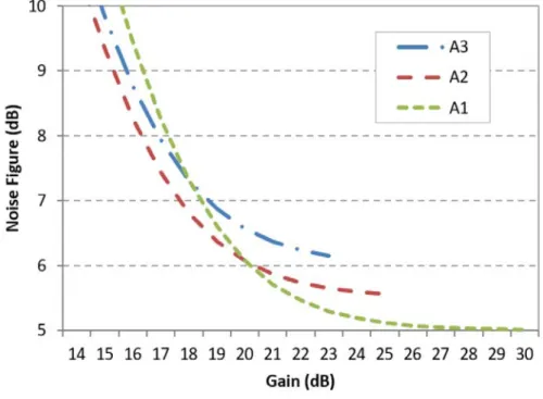
Three main elements are essential to the design of an optical link: the number of channels to establish over the link, optical spans characteristics (i.e., attenuation, physical parameters) and the set of available optical amplifiers. Figure 1.3 shows a set of three optical amplifiers with different characteristics in terms of gain, power and generated noise. Usually, the optical spans constituting the optical link have not nec-essarily the same lengths and thus they have different attenuations requiring probably different types of amplifiers. Therefore, depending on the required gain and the re-quired output power the designer will select the amplifier that generates less noise.
Figure 1.3: Gain variation versus the NF for a set of three optical amplifiers.
The complexity of the link design process arises from the set of opposite objectives. The selected and configured amplifiers should at the same time compensate optical spans attenuations, satisfy the required aggregated optical power while minimizing the generated noise and non-linear effects. The goal is to maximize the capacity and the performance of the optical link by minimizing the generation of linear and non-linear impairments.
![Figure 2.4: Margins and their evolution in a transport optical network [2]](https://thumb-eu.123doks.com/thumbv2/123doknet/11420118.288784/67.892.136.761.182.655/figure-margins-evolution-transport-optical-network.webp)