HAL Id: hal-01421750
https://hal.archives-ouvertes.fr/hal-01421750
Submitted on 9 Jan 2017
HAL is a multi-disciplinary open access
archive for the deposit and dissemination of
sci-entific research documents, whether they are
pub-lished or not. The documents may come from
teaching and research institutions in France or
abroad, or from public or private research centers.
L’archive ouverte pluridisciplinaire HAL, est
destinée au dépôt et à la diffusion de documents
scientifiques de niveau recherche, publiés ou non,
émanant des établissements d’enseignement et de
recherche français ou étrangers, des laboratoires
publics ou privés.
Improvement of fault critical time by HVDC
transmission
Raouia Aouini, Khadija Kilani, Bogdan Marinescu, Mohamed Elleuch
To cite this version:
Raouia Aouini, Khadija Kilani, Bogdan Marinescu, Mohamed Elleuch. Improvement of fault critical
time by HVDC transmission. 8th International Multi-Conference on Systems, Signals & Devices , Apr
2011, Sousse, Tunisia. pp.1 - 6, �10.1109/SSD.2011.5767461�. �hal-01421750�
IMPROVEMENT OF FAULT CRITICAL TIME BY HVDC
TRANSMISSION
Raouia AOUINI
1Khadija BEN KILANI
1Bogdan MARINESCU
2Mohamed ELLEUCH
11
University of Tunis El Manar, ENIT-L.S.E.-BP 37-1002 Tunis le Belvédère, Tunisia,
2ENS-Cachan SATIE 61 Avenue du Président Wilson 94235 Cachan Cedex, France
Email:
aaouinii @yahoo.com
,
khadija.kilani@ept.rnu.tn
,
bogdanmarinescu@hotmail.fr
,
melleuch2005@yahoo.fr
ABSTRACT
This paper investigates the impact of High Voltage Direct Current (HVDC) transmission on the transient stability of a two-machine power system, considering three transmission line configurations: parallel HVAC-HVAC, parallel HVDC-HVDC, and a hybrid HVAC-HVDC operation. The faults are balanced three-phase short-circuits in AC lines, and single phase faults on DC lines, applied in the mid-point of the interconnection. For each configuration, transient stability of the AC systems is assessed in terms of the fault critical clearing time (CCT), and for different DC power levels. The results indicate the contribution of HVDC transmission in increasing the critical clearing time; and therefore enhancing the systems stability margin and operational security.
Index Terms— HVDC transmission, transient stability,
fault critical clearing time.
1. INTRODUCTION
Fault critical clearing time (CCT) is commonly used as the conventional transient stability measure of power system robustness to withstand a given disturbance [1]. This parameter corresponds to the maximum time duration that a disturbance may last without losing the system capacity to recover to a steady-state stable operation. The CCT depends on both the initial operating state of the system, the location ant the severity of the disturbance.
Transient instability in a power system is exhibited in the form of swings in machine angle and grid power. In an interconnected network, power swings in one area may affect the connected areas and cause the instability of the entire network. The instability of frequency or voltage may cause loss of load in an area, transmission line tripping, equipment damage and degradation of power system performance [2].
Several control schemes may be used to prevent this event, for example using power electronic equipment devices, in the form of Flexible Alternative Current Transmission Systems (FACTS) devices, or employing
HVDC systems. In a purely AC system these control devices consist of voltage controls and turbine governor controls. Transmission in Direct Current (DC) offers attractive features such as fast controllability of power through converter control, bulk power transmission, ability to enhance transient stability problems associated with
HVAC lines, asynchronous interconnections,
environmental and economical advantages [4].
Controllability in a DC link is assured by hierarchically organized controls: the master control, the pole control and the converter control [1]. The pole control system is responsible for the firing of the thyristor. On the rectifier side, a proportional integrator (PI) regulator maintains the DC current, whereas on the inverter side, a (PI) regulator controls DC voltage so that minimum losses are archived.
Several studies have emphasized the performance improvements of power systems brought on by HVDC controllability functions [3]. However, in earlier HVDC works, voltage and angle rotor stability have not thoroughly been addressed. Only in recent years, have papers [5 - 9] addressed the issue of voltage stability in AC/DC interconnection. It has been recognized that weak AC/DC interconnection points can limit the power transfer capability of DC links during dynamic operation on account of the transient voltage stability phenomenon [8].
Transient stability has been investigated for a parallel AC and hybrid AC-DC configurations in [10]. Both configurations were subjected to a fault near inverter bus. It has been shown that the presence of a DC link suitably controlled improves the transient stability of the system.
HVDC schemes in parallel operation with AC transmission are prone to both angle and voltage instabilities even for relatively “strong” AC systems [9]. In [9] it has been shown that a HVDC with constant DC power control does not contribute to system synchronizing torque even with supplementary damping signal.
Fundamentally, transient stability is assessed based on synchronizing and damping torques. Lack of sufficient synchronizing torque results in an aperiodic instability, and lack of damping torque results in an oscillatory instability [1].
An important measure for system security is the maximum time interval by which a fault must be cleared in order for the system to preserve its stability this maximum duration is the fault critical clearing time (CCT)
In this paper, we investigate the transient stability of a two-machine power system, considering three transmission line configurations: parallel HVAC, parallel HVDC, and a hybrid HVAC-HVDC. The faults are applied in the mid-point of interconnections. For each configuration, transient stability of the systems is assessed in terms of the CCT. The results indicate the importance of installing HVDC to grid power system not only on increasing the stability margin and the tie-line power control but also increasing the power system critical clearing time.
2. SYSTEM MODELING 2.1 HVDC system
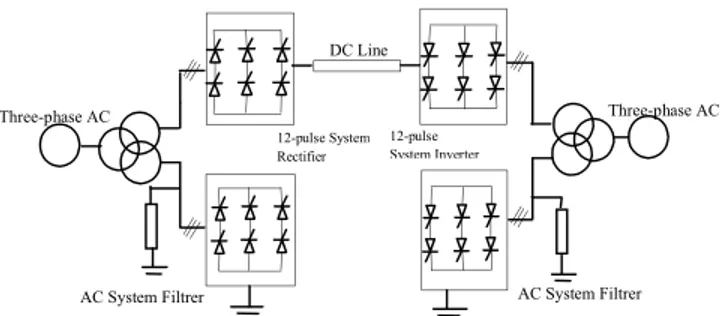
HVDC transmission systems transport very large amounts of electric power which can only be accomplished under tightly controlled conditions. Direct current and voltage are precisely controlled to affect the desired power transfer Pd. It is necessary therefore to continuously and precisely measure system quantities which include at each converter bridge, the DC current Id, its DC side voltage, the delay angle , and for an inverter, its extinction angle . The principles of HVDC control can be well described by the two-terminal monopolar HVDC link schematized in Figure 1, where the rectifier and the inverter are 12‐pulse converters using two 6‐pulse thyristor bridges connected in series. The corresponding equivalent circuit is shown in Figure 2. The strength of the two AC systems connected by HVDC transmission has a significant impact on the AC/DC system interactions. This impact could be measured by the short-circuit ratio (Kcc) when AC filter ratings are excluded [1]: rating (MW) converter DC system AC of (MVA) it shortcircu Kcc (1)
Based on this parameter, the AC system is considered strong or weak. If the Kcc > 3.0 the AC system is considered strong and control systems stability and robustness is not a problem. If Kcc< 3.0, the AC system is considered weak. For such a system, converter controls are difficult to adjust and appropriate tuning is needed [11]. A minimum Kcclevel of 2.5 has often been used as a lower limit for acceptable DC operation [12].
The basic converter equations, for both rectifier and inverter operations, describing the relationship between the AC and DC variables can be written as follows [1]:
0 2( cos ) dr dr cr d V V R I (2) 3 cr cr X R (3) 0 2( cos ) di di ci d V V R I (4)
Figure 1. Single pole 12-pulse HVDC transmission system
Vdr0cos Vdi0cos
Figure 2. Equivalent HVDC transmission system
3 ci ci X R (5) dr di L d V V R I (6) ac d d d P P V I (7) ac d Q P tg (8) 0 0 cos cos -2 dr cr d r dr dr V R I V V (9)
where Vd0rand Vd0irepresent the converter transformer no-load DC voltage of the rectifier and inverter respectively. The equivalent commutation resistances of the rectifier and inverter are respectively Rcrand Rci. The commutation reactance of the converter transformer at the rectifier and inverter are respectively Xcr and Xci. The DC line resistance is denotes by RL. The firing angle for rectifier is , the extinction angle for inverter is ; the current of DC line is Id, the DC terminal voltage of the rectifier and the inverter ends are defined by Vdrand Vdirespectively.
Although several control strategies are suggested for DC link operation, most DC transmission systems use the control concept of constant extinction angle at the inverter with constant current control at the rectifier end. The shift logic of these controllers is implemented by the current in DC line Id which could be derived from the equivalent circuit: 0cos 0cos dr di d cr ci L V V I R R R (10)
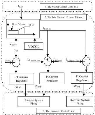
Figure 3 illustrates the basic control scheme of an HVDC link. An HVDC system can be divided into several levels. The master control layer determines the reference current Id_ref, which indeed decides the active power to be transmitted. The actual reference current Id_ref_limused by the controllers is limited by the Voltage Dependent Current Order Limiter (VDCOL), which is implemented to help the fault recovery. This control automatically reduces the reference current Id_refset point when Vd_mesdecreases (as, for example, during a DC line fault or a severe AC fault). RL Rci Rcr Vdi Vdr Id AC System Filtrer AC System Filtrer Three-phase AC Three-phase AC 12-pulse System Rectifier 12-pulse System Inverter DC Line
Reducing the Id_refcurrents also reduces the reactive power demand on the AC system, helping to recover from the fault. The difference between both settings is the current margin Imarginand its value is normally fixed in the range of 10%‐15% of the system rated current.
The current error Imarginprovides a transition between
the current control and voltage control to facilitate control stabilization. The Pole control is the core of HVDC control and activates the appropriate controller of the rectifier and inverter station according to the state of AC/DC systems. Then it produces the firing angleordfor both rectifier and inverter stations. The constant current mode at the rectifier is achieved using a typical PI regulator, which acts according to the error obtained from the measured and the desired current to keep the direct current constant. Pole control of the inverter station includes a constant current (CC) controller and a PI a constant extinction angle (CEA) controllers in order to maintain a constant voltage at the inverter end. Finally, the bridge or converter unit control determines the firing instants of the valves within a bridge. This has the fastest response within the control hierarchy.
2.2 AC and DC transmission line model
The DC transmission line is represented using the distributed parameter line model with lumped losses. For an AC transmission line, the resistance, inductance, and capacitance are uniformly distributed along the line. Unlike the distributed parameters line block, which has an infinite number of states, the sections linear model has a finite number of states that permits to compute a linear state-space model.
3. TRANSIENT STABILITY CRITERIA Transient stability is the ability of the power system to maintain synchronism when subjected to a severe transient disturbance such as a short-circuit on a transmission line. The resulting system response involves large excursions of generator rotor angles and is influenced by the nonlinear power-angle relationship [1]. The conventional transient stability measure of power system robustness to withstand a given disturbance (e.g., its stability degree) is named Critical Clearing Time (CCT), which is the maximum time duration that the disturbance may act without losing its capacity to recover to a steady-state (stable) operation. The CCT depends on both the initial operating state of the system, the location and the severity of the disturbance [1].
4. TEST POWER SYSTEM
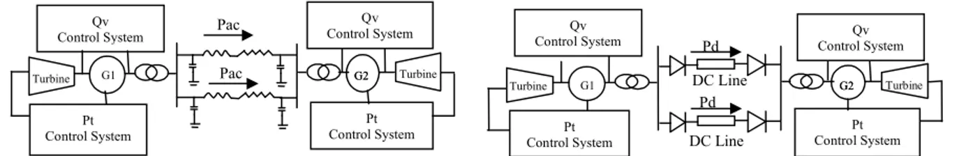
The proposed test power systems consist of two finite control areas interconnected via different HVDC and HVAC parallel line configurations. Each control area is represented by a turbine generator set equipped with power frequency and voltage reactive power control systems, an area load (Pload), and a system interconnection bus. An overview of the test power systems is shown in Figure 1.
Figure 3. Basic HVDC control scheme
For each AC system, the synchronous generator is represented by a sixth order dynamic model; the excitation system is represented by a third order dynamic model, the model parameters are given in the Appendix. The AC systems have identical nominal voltages, frequency, and short-circuit powers (U = 500 kV, f = 50 Hz; Scc= 5000
MVA). They are considered as strong systems since the
corresponding short-circuit ratio (Kcc) is equal to 5). The model presented in Figure 4 includes two types of buses according to Table 1:
Table 1: Model load flow data
The DC system is a bipolar, 12 pulse, rated 1000 MW
(1000 A, 500 kV). The rectifier (sending end) and the
inverter (receiving end) are separated by a 100 km transmission line. The HVDC transmission line has the configuration with two ends (point to point). The converters stations use thyristor valves. The simulations are performed with the Toolbox SimPower Systems of MATLAB.
The no-load DC voltage is computed by:
0 3 2 3 2 0.96* 200 288.1 0.9 dr c V V kV (11)
The equivalent commutation resistance of the rectifier is computed from equation (3):
3 9.429 cr cr X R (12)
Generated Power (MW) P load(MW)
Bus 1 2915 1000 Bus 2 1000 3000
2. The Pole Control 10 ms to 500 ms
γref Id_ref_lim PI Current Regulator Imargin Id_meas_inv Inverter System Firing Rectifier System Firing VDCOL
1. The Master Control Up to 10 s
Id_meas_rec
3. The Converter Control 1 ms
Vd_meas ord PI Gamma Regulator ord PI Current Regulator ord Id_ref
Id_ref *Id_min Id_ref
Figure 4(a). Parallel HVAC transmission line
Figure 4(b). Hybrid HVAC-HVDC transmission line
Where Vc is the line-to-line RMS commutating voltage which depends on the AC system voltage and the transformer ratio. The terminal DC voltage Vdr at the rectifier end is computed from its expression in (2): Vdr2(Vdr0cosR Icr d) 514.7 kV (13) Referring to equations (8) and (9), the power factor and the reactive power consumption are about:
0 0 cos cos 0.893 2 dr cr d r dr dr V R I V V (14) QacP tgd 503MVAR (15) 5. SIMULATION RESULTS
The time domain simulation method is chosen to assess the transient stability of a power system because it is the most accurate method compared to direct methods. The differential equations to be solved are nonlinear ordinary equations with known initial values. In this work, the trapezoidal technique is used considering the fact that it is widely used for solving electro-mechanical differential algebraic equations.
When a three-phase fault occurs at any line in the system, a breaker will operate and the respective line will be disconnected at the Fault Clearing Time (FCT) which is set by the user. If the relative rotor angles with respect to the slack generator remain stable after the fault is cleared, it implies that FCT < CCT and the power system is stable. However, if the relative angles go out of step after the fault is cleared, FCT > CCT and the system is unstable.
Methodologically, the type of contingencies
considered are three-phase balanced faults created at the mid-point if the AC tie-lines and single phase faults applied on the DC tie-lines. For comparison, the study considers three different tie-line configurations:
Figure 4(c). Parallel HVDC transmission line
- Configuration 1: Parallel HVAC-HVAC (Fig 4(a)) - Configuration 2: Hybrid HVAC-HVDC (Fig 4(b)) - Configuration 3: Parallel HVDC-HVDC (Fig 4(c)) 5.1 Comparative Analysis
The simulation tests were carried out to compare system dynamic responses of the above three configurations for four scenarios are tested:
Case 1: Configuration 1- Parallel HVAC-HVAC
A three phase short-circuit fault occurs at the mid-point of the AC transmission line. A critical time noted CCTAC//AC
is determined (Table 2). The simulation results depicted in Figure 5 shows the speed machine 2 for the stable and the unstable cases.
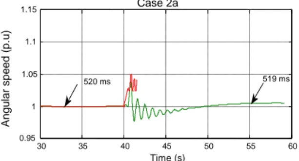
Case 2a: Configuration 2a - Hybrid HVAC-HVDC
A three phase short-circuit fault occurs at the middle of AC transmission line. A critical time noted CCTAC//DC-ais determined (Table 2). Figure 6 shows the angular speed of machine 2 for the last stable simulation (FCT<CCTAC//DC-a) and for the unstable case (FCT > CCTAC//DC-a).
Case 2b: Configuration 2b- Hybrid HVAC-HVDC
A single phase short-circuit fault occurs at the mid-point of the DC transmission line. The critical clearing time noted CCTAC//DC-bis determined (Table 2) and the results are shown in Figure 7.
Case 3: Configuration 3- Parallel HVDC- HVDC
A single phase short-circuit fault occurs at the mid-point of the DC transmission line. The critical clearing time noted CCTDC//DCis determined (Table 2, Figure 8).
In all the above cases, the CCT is obtained by increasing the fault duration gradually until the system loses its stability.
Table 2: Critical clearing time for different cases
According to Table 2, the fault critical clearing time for case 1 estimated at CCTAC // AC = 424 ms is less than for the mixed system of case 2a where the CCT was estimated at CCTAC//DC-a = 519 ms. As a result, the addition
of parallel DC lines to AC transmission circuit improved CCTAC//AC (ms) CCT(ms)AC//DC-a CCT(ms)AC//DC-b CCT(ms)DC//DC 424 519 100 180 DC Line Turbine Pt Control System Qv Control System Pt Control System G1 G2G2 Pac Turbine Qv Control System Pd Turbine Pt Control System Turbine Qv Control System Qv Control System Pt Control System G1 G2G2 Pac Pac DC Line Pt Control System DC Line Pt Control System G1 G2G2 Pd Pd Turbine Qv
Control System Control SystemQv
Figure 5. Angular speed of machine 2
Figure 6. Angular speed of machine 2
the transient stability of the network. For case 3, the critical fault duration is estimated at CCTDC//DC= 180 ms. When compared to the DC line fault in the hybrid configuration case 2b (CCTAC//DC-b = 100 ms), the former
case resulted in a higher allowable fault duration time. This result further confirms the improvement of system transient stability by adding the DC transmission. 5.2 Influence of AC-DC interconnection ratio
In the following, the influence of the relative capacity of the HVDC and the parallel AC transmission is investigated. The ratio between the active power transmitted and the continuous power to HVDC line is defined by a ratio R: ac d P R P (16) where Pacis the active power transmitted by the AC line (MW) and Pd is the continuous power line DC (MW). According to [9], the strength of an AC line is classified as high or low depending on the value of R:
R ≥ 1.5: the AC line is strong
R ≤ 0.7: the AC line is weak
The reference power of the DC line noted Pd_ref DCis varied
(Pd_ref_DC = 800 MW, 1000 MW, and 1300 MW) keeping
constant the total transmitted power:
PT= Pd+ Pac= constant (16)
Figure 7. Angular speed of machine 2
Figure 8. Angular speed of machine 2
A three short-circuit fault at the mid-point of the AC line is applied and the corresponding CCT is determined. Two different cases were considered: the case when the capacity of the parallel AC transmission Pacis much less than the DC power Pdwith R=0.63; and the case when the capacity of the AC transmitted power Pacis higher than the DC power Pdwith R=1.66. The results presented in Table 3 show the positive impact of the increased ratio on the CCT.
The increase of the DC current significantly reduces the momentary AC power transfer capability; improving therefore the CCT, and hence increasing the stability margin of the network when the AC line becomes weaker. In fact, in a DC transmission, DC transmitted power is independent from the AC transmission angle δ. This possibility is often used to improve the performance and efficiency of the connected AC networks. The controllability of the HVDC power is often used to improve the operating conditions of the AC networks where the converter stations are located.
Table 3. Critical clearing time with DC power levels
Direct Power Pd(MW) AC power Pac (MW) ac d P R P CCT (ms) 800 1330 1.66 450 1000 1130 1.13 519 1300 830 0.63 526 0 10 20 30 40 50 60 70 80 0.7 Time (s) 0.8 0.9 1 1.1 1.2 1.3 1.4 Case 2b A n g u la r s p e e d ( p .u ) 30 35 40 45 50 55 60 0.95 1 1.05 1.1 1.15 Time (s) 520 ms 519 ms A n g u la r s p e e d ( p .u ) 10 20 30 40 50 60 70 0.95 1 1.05 1.1 1.15 1.2 1.25 Time (s) CCT=424 ms 425 ms A n g u la r s p e e d ( p .u ) 10 15 20 25 30 35 40 45 50 0.998 Time (s) 0 5 1 1.004 1.006 1.012 1.014 1.016 Case 3 1.002 1.01 1.008 Case 2a Case 1 A n g u la r s p e e d ( p .u )
5. CONCLUSION
In this paper, the impact of HVDC interconnections on transient stability is investigated. Three transmission line configurations are considered: parallel HVAC, parallel HVDC, and a hybrid HVAC-HVDC transmission line. For each configuration, transient stability of the system is assessed in terms of the fault critical clearing time. Due to the rapid and controllable features, HVDC systems can be used to improve the transient stability of interconnected AC systems in terms of increasing the fault critical clearing time.
For the hybrid HVAC/HVDC transmission system, the rapid and controllable features of HVDC system can also be used to control the power flow in AC systems, so as to increase AC lines transmission capacity and transient stability margin. The protection systems in HVDC transmission are ignored in this work.
Acknowledgment
This work has been supported by the Tunisian-French project CNRS/DGRDRT project Code: 09/R11-09 entitled “Stability of interconnected power systems integrating
decentralized production. Case of the south Mediterranean countries”.
"This work was supported by the Tunisian Ministry of High Education, Research and Technology"
References
[1] P. Kundur, Power system stability and control, McGraw-hill, 1994.
[2] Hassan Bevrani, Robust Power System Frequency Control, 2009 Springer Science+Business Media, LLC.
[3] Hualei Wang; Redfern, M.A ‘’the advantages and disadvantages of using HVDC to interconnect AC networks, Universities Power Engineering Conference (UPEC), 2010 45th International.
[4] Kala Meah, Sadrul Ula, ‘’Comparative Evaluation of HVDC and HVAC Transmission Systems’’, Power Engineering Society General Meeting, 2007. IEEE
[5] W. Yuan and Y. Zhang, “Study of the Static Voltage Stability in Multi-Infeed AC/DC System”, 2005 IEEE/PES Transmission and Dustribution Conference & Exhibition: Asia and Pacific Dalian,China.
[6] Nguyen, M.H.; Saha, T.K.; Eghbal, M’’A comparative study of voltage stability for long distance HVAC and HVDC interconnections Power and Energy Society General Meeting, 2010 IEEE.
[7] M. Khatir, H. S. Zidi, Sid Ahmed, and M. K. Fellaf, “Analysis of recovery from commutation failures in an HVDC inverter connected to a weak receiving ac system,” Acta Electrotechnica et Informatica, vol. 8, no. 1, pp. 44–50, 2008.
[8] L. Pilotto, M. Szechtman, A. Hammad, "Transient AC Voltage Related Phenomena for HVDC Schemes Connected to Weak AC Syslems", lIEEE (Trans., PWRD, July 1992, pp. 1396-1404.
[9] A. E. Hammad, “Stability and Control of HVDC and AC Transmission in Parallel,” IEEE Transactions on Power
Delivery, Vol. 14, no. 4, pp.1545-1554 October 1999.
[10] N.A.Vovos, G.D. Galanos, Transient stability of ac–dc system, IEEE Trans. Power Apparatus Syst. PAS-98 (4) (1979) 1375–1383.
[11] S. Lefebvre, M. Saad, R. Hurteau, Adaptive control for HVDC power transmission systems, IEEE Transactions on Power Apparatus and Systems, vol. PAS-104, No. 9, September 1985, pp. 2329–2335.
[12] Kala Meah, A.H.M. Sadrul Ula , A self-coordinating adaptive control scheme for HVDC transmission systems, Electric Power Systems Research 79 (2009).
Appendix
The parameters of the system are:
Generators: Rated 5000 MVA, 13.8 kV
Rotor type: Salient-pole xl(p.u) : leakage Reactance = 0.18
xd(p.u.) : d-axis synchronous reactance = 1.305 ,T’d0(s): d-axis open
circuit transient time constant =0.296
T’d0(s): d-axis open circuit transient time constant = 1.01
Xq(p.u ) : q-axis synchronous reactance = 0.053 ,Xq(p.u ) : q-axis
synchronous reactance = 0.474 ,X’’q (p.u) : q-axis sub transient reactance =0.243 T’’q0(s): q-axis open circuit sub transient time constant=0.1 M =
2H (kWs/kVA): Mechanical starting time = 7.4
Governor control system:
Permanent droop (statisme) R= 4 % Servo-moteur ka= 10/3, ta= 0.07 s
Regulation PID kp= 1.163, ki= 0.105, kd= 0
Gate opning limit gmax= 0.01, gmax=0.97518
Gate speed limit Vgmin=-0.1 Vgmax= 0.1(p.u/s)
Excitation control system:
Amplifier gain Ka = 200, Amplifier time constant Ta= 0.001
Exciter gain ke = 1, Exciter time constant te= 0 s
Damping filter gain kf= 0.001, time constant te= 0.1 s
Regulator output limits Efmin= 0, Efmax= 7
Initial value of terminal voltage Vt0 =1,
Initial value field voltage Vf0= 1.35725
Generator transformers Rated 5000 MVA, 13.8/ 500 kV
Coupling Delta/ Yg
Primary resistance (p.u) =0.002, Primary inductance (p.u) =0.12 Secondary resistance (p.u) =0.002, Secondary inductance (p.u) =0.12
Converter transformers: Rated 1200 MVA, 500 kV/200 kV/200 kV
Coupling Yg/Y/Delta Leakage inductance=18%
The tap position on the rectifier side nr=0.96
The tap position on the inverter side ni =0.9
AC transmission lines
Resistance per phase (Ω/km) =0.03 Inductance per phase (mH/km) =0.32 Capacitance per phase (nF/km) =11.5
Dc transmission line Rdc = 0.015 Ω /km, L = 0.792 mH/km, C = 14.4 nF/km Smoothing inductances: 0.5 H Smoothing resistance: 1 Ω Converters: Rectifier Controller:
Current regulator Kp = 45 deg/pu , Ki = 4500 deg/pu/s
Rectifier firing angle (steady-state) α = 16.5°
Inverter Controller:
Inverter extinction angle (steady state) = 142°;
Current regulator Kp = 45 deg/pu , Ki = 4500 deg/pu/s
Gamma regulator Kp = 1 deg/degKi = 20 deg/deg/s Current margin: Imargin= 0.1 p.u.