HAL Id: hal-02087643
https://hal.telecom-paris.fr/hal-02087643
Submitted on 2 Apr 2019
HAL is a multi-disciplinary open access
archive for the deposit and dissemination of
sci-entific research documents, whether they are
pub-lished or not. The documents may come from
L’archive ouverte pluridisciplinaire HAL, est
destinée au dépôt et à la diffusion de documents
scientifiques de niveau recherche, publiés ou non,
émanant des établissements d’enseignement et de
High-level modeling of communication-centric
applications: Extensions to a system-level design and
virtual prototyping tool
Daniela Genius, Ludovic Apvrille, Letitia Li
To cite this version:
Daniela Genius, Ludovic Apvrille, Letitia Li. High-level modeling of communication-centric
appli-cations: Extensions to a system-level design and virtual prototyping tool. Microprocessors and
Mi-crosystems: Embedded Hardware Design (MICPRO), Elsevier, 2019, �10.1016/j.micpro.2019.03.006�.
�hal-02087643�
High-Level Modeling of Communication-Centric
Applications: Extensions to a System-Level Design and
Virtual Prototyping Tool
Daniela Geniusa, Ludovic Apvrilleb, Letitia W. Lib,c
aSorbonne Universit´e, LIP6, CNRS UMR 7606, daniela.genius@lip6.fr
bLTCI, Telecom ParisTech, Universit´e Paris-Saclay, ludovic.apvrille@telecom-paristech.fr cInstitut VEDECOM, 77 Rue des Chantiers, 78000 Versailles, France,
letitia.li@telecom-paristech.fr
Abstract
High performance streaming applications require hardware platforms featuring complex, multi-level interconnects. These applications often resemble a task-farm, where many identical tasks listen to the same input channel. Usual em-bedded system design tools are not well adapted to capture these applications. In particular, the non-uniform memory access (NUMA) nature of the platforms induces latencies that must be carefully examined. The paper proposes a multi-level modeling methodology and tools (TTool, SoCLib) that have been extended to model the characteristics of streaming applications (multiple tasks, non deter-ministic behavior, I/O devices) in UML/SysML, and to automatically generate a virtual prototype that can be simulated with high precision. The paper uses a typical streaming application to show how latencies can be estimated and fed back to diagrams.
Keywords:
Virtual prototyping, System-level design, Design space exploration
1. Introduction
Parallel telecommunication and video streaming applications often adhere to the task-farm paradigm: they contain a high number of tasks, each waiting to accept data for processing from one of the common (input) buffers. Streaming applications also have the particularity that they require specific Input/Output (I/O) co-processors which read from, for example, an Ethernet link and, after processing by the application, write to another link or display video streams on a display.
Multiprocessor-on-chip system (MPSoC) architectures feature complex, some-times hierarchical, interconnect-on-chip architectures: they are thus well adapted for the deployment of highly parallel applications. These MPSoC usually rely on Non Uniform Memory Access (NUMA), where clusters using local crossbars are
grouped around a central interconnect. In these architectures, memory access latencies are hard to predict, thus resulting in non deterministic behaviors.
Design space explorations can help predicting application timings. Ideally, the design space exploration should be performed at a high level of abstraction so as to minimize the design effort to dimension the application and the under-lying architecture. However, since high-level models are highly abstracted, it means that decisions are taken with high-level parameters that should be verified later in the system design process using more precise modeling and simulation schemes (e.g. cycle accurate simulations).
Tool support is certainly required to carry out this method. Yet, in the field of classical embedded systems for which many high-level modeling and exploration tool exists, communications are typically one-to one and do not fully exploit the capacities of such architectures e.g. the standard interconnect is a (simple) bus.
Our previous work [1, 2] enabled the multi-level modeling of high throughput task-farm applications, by providing a formal basis for non-deterministic chan-nel accesses and extended TTool to model NUMA architectures and generate NUMA virtual prototypes. However, while streaming applications strongly rely on I/O elements, it was not possible to model these elements. Neither could we explicitly take into account the very strong variations of latencies, e.g. for mermory access, in the model.
In summary, our contribution presents an overview of new and existing work on a model-based engineering (MBE) approach for complex task-farm type streaming applications with a presentation of the overall method, the semantics, modeling extensions, as well as a comprehensive case study.
The paper is organized as follows. Section 2 presents the related work.
Section 3 presents the background frameworks. Section 4 explains extensions of the semantics to capture non-determinism, and of the hardware model to
convene for our class of applications. Section 5 illustrates the approach by
means of a case study, for which experimental results are presented in Section 6. Section 7 concludes the paper and gives our perspectives.
2. Related Work
During an embedded software development process, software components are generally tested/executed on a local host, and then are integrated once the target is available. The lack of information regarding software/hardware interactions
often leads to late and costly software revisions. Moreover, reconsideration
of software design choices may strongly impact MPSoC design, because they feature a high number of processor cores and complex interconnection networks. Thus, we require a fast and easy-to-use solution for a preliminary high-level exploration.
One possible approach is to frequently validate the different refinements of software components in a as-realistic-as-possible hardware environment. Flexi-ble ProgrammaFlexi-ble Gate Arrays (FPGAs) can be used for this purpose [3, 4], but
the hardware elements must be totally developed to include a sufficient amount of details, and then flashed onto a —sometimes costly— FPGA.
A less expensive solution is the use of virtual prototyping platforms. They are slower and less realistic than FPGAs, but offer more flexibility, and are more accessible for software engineers with limited hardware knowledge.
Many completely software-based prototyping environments have been pro-posed. Some of them are restricted to high-level analysis and offer only func-tional simulation, while others offer virtual prototyping and extended profiling capabilities.
PtolemyII [5] proposes a modeling environment for the integration of diverse execution models, in particular hardware and software components. Even if design space exploration can be performed, its first intent is the simulation of the modeled systems.
In Polis [6], applications are described as a network of state machines. Each element of the network can be mapped on a hardware or a software node. This approach is more oriented towards application modeling, even if hardware com-ponents are closely associated to the mapping process. Metropolis [7], an exten-sion of Polis, targets heterogeneous systems and offers various execution models. Architectural and application constraints are however closely interwoven.
Sesame [8] proposes modeling and simulation at several abstraction levels. In contrast to Metropolis, application and architecture are clearly separated in the modeling process. Models’ semantics vary according to the levels of abstraction, ranging from Kahn process networks (KPN [9]) to data flow for model refine-ment, and to discrete events for simulation. Currently, Sesame is limited to the allocation of processing resources to application processes. It neither models memory mapping nor the choice of the communication architecture.
The ARTEMIS [10] project originates from heterogeneous platforms in the context of research on multimedia applications in particular, thus justifying the acronym (ARchitecTurEs and Methods for embedded MedIa Systems); it is strongly based on the Y-chart approach. Application and architecture are clearly separated: the application produces an event trace at simulation time, which is read in by the architecture model. However, behavior depending on timers and interrupts cannot be taken into account.
MARTE [11] shares many commonalities with our approach, in terms of the capacity to separately model communications from the pair application-architecture. However, it intrinsically lacks separation between control aspects and message exchanges. Other works based on UML/MARTE, such as Gas-pard2 [12], are dedicated to both hardware and software synthesis, relying on a refinement process based on user interaction to progressively lower the level of abstraction of input models. Still, such a refinement does not completely sep-arate the application (software synthesis) or architecture (hardware synthesis) models from communication. Finally, MARTE neither offers explicit support for task-farm applications nor for NoC and NUMA based platforms.
Di Natale et al.[13] propose the generation of communication managers for software low layers. Yet, they do not handle the specificity of task-farm appli-cations nor do they offer formal verification.
Batori [14] proposes a design methodology specific for telecommunication applications. From use cases, the method proposes several formalisms to cap-ture the application struccap-ture (“interaction model”) and behavior (Finite State Machine) and for its deployment from which executable code can be generated. The platform seems limited to specific components and no design exploration seems possible; code generation targets a real platform, and not a prototyping environment.
An important aspect of streaming applications is I/O, requiring hardware modules for the sending and receiving of network packets or video frames either from a network, a file or other source. Often very specific, they are difficult to model in tools for modeling generic applications [15, 16].
We therefore propose an approach to address all aspects of such applications, in terms of software and hardware modeling, formal verification, simulation, and performance evaluation, using a model-driven approach and existing toolkit as a basis.
3. Background 3.1. Supporting Toolkit
TTool [17] is a UML/SysML modeling and verification toolkit for designing embedded systems, supporting different level of abstraction, and proposing a push button approach for both simulation and formal verification.
3.1.1. Modeling Levels
The main abstraction levels of TTool are partitioning and software design [18]. The software design level includes a prototyping phase in which software can be simulated onto the hardware using a precise simulation engine.
As shown in Figure 1, the approach is as follows:
1. The overall method starts by a partitioning phase, DIPLODOCUS (De-sIgn sPace expLoration based on fOrmal Description teChniques, Uml and SystemC), containing three sub-phases: the modeling of the functions to be realized by the system (functional view), the modeling of the candidate architecture as an assembly of highly abstracted hardware nodes, and the mapping phase. A function mapped on a processor is a software function, a function mapped on a hardware accelerator corresponds to a custom ASIC (Application-specific Integrated Circuit).
2. The second phase is based on AVATAR (Automated Verification of reAl Time softwARe [19]), a SysML-based environment for modeling the soft-ware components of complex embedded systems. It starts by the design of the software and hardware. A deployment view shows the allocation of software components. Code can then be generated both for the software components of the application (in C/POSIX code) and for the virtual hardware nodes (in System C format).
Final software code Refinements VHDL/Verilog Software Design and Prototyping (AVATAR) Deployment view ... ... Hardware design Abstractions Abstractions Reconsideration of partitioning decisions Simulation and Verification : safety, security and performance Mapping view
Functional view Architecture view
Software Component Hardware
model Partitioning with Design Space Exploration techniques (DIPLODOCUS)
Figure 1: Overall Approach from [18]
Choice of parameters at the higher level of abstraction is subject to validation or invalidation due to experimental results on the generated prototype. Thus, simulation results at the prototyping level could lead to reconsideration of the partitioning decisions.
At each stage, simulation and formal verification ensure that our design meets performance, behavior, and schedulability requirements [20]. Simulations and verifications first rely on model transformation techniques e.g. SysML-to-formal specification. Safety properties can be evaluated using the TTool internal model checker or with UPPAAL [21], while security properties can be proved with ProVerif [22].
3.1.2. Simulation
From partitioning models, high-level simulation can be performed. From software design models, an application and its deployment can be transformed into a virtual prototype [23] based on SoCLib [24], a public domain library of component models written in SystemC. SoCLib targets shared-memory MPSoC architectures based on the Virtual Component Interconnect (VCI) protocol [25]. This protocol clearly separates the components functionality from communica-tion aspects; we use Cycle/Bit Accurate component models.
Basically, the transformation works as follows. Each SysML block is trans-lated into a POSIX thread and executed on one of the general purpose proces-sors. The threads uses on primitives defined in the AVATAR runtime. These primitives capture the semantics of the AVATAR operators (delay, asynchronous read, etc.) and implement them using C/POSIX calls. The main program in-stantiates the POSIX threads of the AVATAR blocks, and the channels trans-lated as software objects stored in the on-chip memory. Threads are spawned from the main thread on the CPU indicated in the deployment diagram. The
top cell generator generates a SystemC top cell from the deployment diagram. A ldscript generator generates the linker script taking into account the mapping specified in the deployment diagram.
3.1.3. Capturing non deterministic behaviour
In [1], we have shown how to rely onnon-deterministic operators of timed automata in order to capture multi-writer multi-reader (MWMR) communica-tions as already explained in in [26] i.e. any number of reader or writer tasks can access simultaneously to these channels. In other words, a task waiting for some data to be processed indifferently picks up data from common buffers, thus introducing a high degree of non deterministic behaviors that are difficult to capture in FIFO models (e.g., Kahn models). However, at the time, these channels lacked formal semantics, and generation of platform variants was text-based and semi-automatic. Due to our contributions, it is now possible to work from high-level models, generate the prototyping code and feed the results back to the higher-level diagrams.
<<block>> B0 ~ out m0() ~ out m1() <<block>> B1 ~ in m0() ~ in m1() m0() state0 m1() Waiting4Sig m1() m0() after (2,12) after (5,15) after (10,20)
Figure 2: Non-deterministic AVATAR model
An example of non deterministic behavior —using the after clause of SysML state machines— is shown on the left side of Figure 2 where two SysML blocks communicate via a channel. Asynchronous channels can be rather naturally implemented using multi-writer multi-reader channels. In the figure, AVATAR asynchronous channels are depicted with origin and termination ports filled in white. The right part of the figure shows the state machine diagrams of blocks B0 and B1, respectively. This is a non deterministic system since e.g. B0 can decide to send either m0 or m1. B1 waits for one of the two messages, or if a given time without receiving one of the two (“after(10,20)”) passes, it resets the waiting time of messages by taking the top right transition from its main state. 3.1.4. Modeling task-farm applications in TTool
In the field of embedded systems, communications are typically one-to one, more rarely one-to-many e.g. broadcast communication. Many-to-many com-munications are not common practice. Block hierarchy can be used to express the fact that several blocks write to the same channel, as shown in previous work [1].
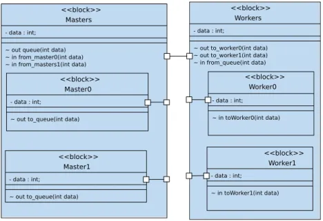
Figure 3 shows a typical task-farm application modeled as AVATAR block diagram. Masters and Workers are connected through an AVATAR channel regrouping all communication between the master and worker tasks (i.e. the common channel). The master blocks have to be put into a higher-level block called Masters, writing indifferently to the channels, and the worker into a higher-level block Workers, reading the channels, respectively. Figure 4 does not show the state macines of the inner tasks which are very simple, but only the two outer tasks. The Masters task reads data produced by either one of the two inner tasks Master0 and Master1 via channel from master0 and from master1, the Workers task dispatches data to either one of the two inner tasks Worker0 and Worker1 via channel from worker0 and from worker1.
<<block>> Masters
- data : int; ~ out queue(int data) ~ in from_master0(int data) ~ in from_masters1(int data)
<<block>> Master0
- data : int;
~ out to_queue(int data)
<<block>> Master1
- data : int;
~ out to_queue(int data)
<<block>> Workers
- data : int;
~ out to_worker0(int data) ~ out to_worker1(int data) ~ in from_queue(int data) <<block>> Worker0 - data : int; ~ in toWorker0(int data) <<block>> Worker1 - data : int; ~ in toWorker1(int data)
Figure 3: Task farm application: block diagram
3.2. Support for NUMA Architectures
TTool, up to the work described in [2], did not provide support for modeling NUMA virtual platforms. A NUMA architecture typically addresses at least two computing domains. TTool has been extended to handle NUMA architectures thanks to the following contributions:
• Modeling aspects. A local crossbar component and the possibility to con-nect communication components (crossbar, bus, mesh, ...) with each other to build multi-level interconnects have been added. TTool is still limited to two-level interconnects featuring local crossbars around either a Virtual Generic Multi Network (VGMN), abstraction of a n × m mesh intercon-nect, or a Virtual Generic Serial Bus (VGSB), abstraction of a serial bus.
queue(data) Waiting dispatch from_master0(data) from_masters1(data) to_worker1(data) to_worker0(data) from_queue(data) Waiting Dispatch after (10,50)
Figure 4: Task farm application: master and worker hierarchical tasks
• Model transformation. Automated code generation for NUMA architec-tures has been added. While the model-to-code translation of software tasks and the generation of a main program remains mostly the same with respect to what was described in [23], the topcell (in particular the determination of the segment’s addresses in the mapping table) as well as the ldscript are far more complex. Using a two-level interconnect in the shared memory paradigm means that addresses and segment sizes, which are automatically generated by the tool, must avoid overlapping and re-spect cluster rules (in Most Significant Bits) and local address; local and shared memory segments have to be generated. Each cluster contains at least one RAM. Additional infrastructures which are invisible from the SysML level are replicated on the clusters, such as DMA and interrupt controllers.
3.3. Capturing Latencies
NUMA platforms usually have a high access latency variance, because time required for memory access differs depending whether data is located on the same or a different cluster. To better study timings, our idea is to rely on multi-level modeling and verification. To do so, we use a refinement relation R defined in [27] that can help to better trace latencies between the different modeling levels.
More precisely, the refinement relation allows us to split tasks into sub-tasks and to replace high-level complexity operators by a concrete sub-behavior. When a task is split into sub-tasks, internal communication must be added be-tween sub-tasks. Figure 5 shows the relation bebe-tween Partitioning and Software Design models. Latencies are determined between a pair of operators on the same execution path. By performing simulations on either of the two levels, we obtain the occurrences of channel operators (right hand side of the figure) and
can then derive minimum, maximum and average latencies by comparing the times they were reached. The selected latency checkpoints are marked by blue flags on the left hand side of Figure 5, the same in the state machines of TTool diagrams. sig() state0 sig() sig() state1 state2
Partitioning
Before mapping evt event() chl channel(size) Algorithm ComplexityChannel OperatorAfter mapping Channel Transit Time Algorithm Execution Time Event Operator Latency
Software Design
Channel Signal Operator Channel Time Function Algorithm Time Function Event Signal Operator Latency
Modeling Execution on Target
calculateAlgorithm signal1(attribute)
signal2()
Figure 5: Relation between latencies in Partitioning and Software Design Models from [27]
4. Contributions
This section discusses how we have further extended our approach from [1, 2] to obtain a more realistic virtual prototype at deployment level. Thus, in order to better capture the behavior of parallel streaming applications, two kinds of extensions are proposed. First, the effects of complex interconnect architectures and resulting high variability of memory accesses should be captured in the model in order to conduct formal verification. Second, the effects of I/O devices that are typical for streaming application should be captured in sufficient detail to show the impact on performance and allow design space exploration. 4.1. Latency Feedback between Modeling Levels
Latency requirements on channels are annotated by the designer in the TTool diagrams. In our experiments, we focus on average latencies between events. This is due to the fact that latencies vary enormously, depending if memory is accessed in the local or on a distant cluster.
There are two kinds of problems that are now automatically detected: if the simulation of the virtual prototype at the current abstraction level does not meet the requirement, or if it deviates from more than an indicated percentage, diagrams are annotated accordingly. Deviating latencies appear in red. Model adaptations to solve the problems are however still manual.
4.2. Modeling I/O Co-processors
Input/Output co-processors are hardware or software tasks. In both cases, they take as input a stream of packets, images or video and transform it into a format that the platform can efficiently handle. TTool, up to now, did not provide support for any kind of streaming I/O simulation. We have integrated into TTool high-level representations of some existing models of packet and video streaming co-processors from the same previous work.
The corresponding cycle-accurate SystemC hardware components have now been added to our virtual prototyping environment. In the Deployment Dia-grams in [2], we used the existing MWMRCoporoc blocks to indicate an interface to the I/O block. The block as such was visible in the block diagram, and was software.
This diagram is no longer semantically correct when a block is hardware. It should then appear on the partitioning level. In the Deployment Diagrams on Software design level, the corresponding blocks now have a new semantics. A corresponding block, called Hardware Accelerator (HWA), becomes available. This somewhat relaxes a paradigm of TTool which requires that no hardware is visible in the Software Design (AVATAR) diagrams, but is necessary to generate the channels leading to and from the interface.
Figure 6: Co-processor interface
The hardware wrapper called VCI MWMR Controller shown in Figure 6 was first presented in [26]. It is used to connect HWA featuring a FIFO
in-terface to the rest of the platform. It provides a VCI initiator and target VCI interface, read and write FIFO interfaces of configurable number, a status and a configuration register.
Wrapper and I/O co-processor instances, signals and netlist as well as the ldscript have to be generated automatically by TTool if they appear in the Deployment Diagram. The fact of adding such detailed models of hardware I/O to the virtual platform thus has significant impact on the generation of top-cell and ldscript and contributes further to the added complexity described in 3.2.
Our contributions, previous and new ones, are now shown throughout a comprehensive case study.
5. Case Study
A particularly interesting telecommunication application is the parallel clas-sification of communication packets, as described in [28]. Task farm properties were captured by Multi-Writer Multi-Reader (MWMR) within channel mapped to shared memory, where an arbitrary number of —hardware or software— tasks access to the same channel.
One of the results of the above work was a detailed analysis of the difficulties and sources of performance loss for this particular application:
• Complex semantics of Multiple-Writer Multiple-Reader channels • Complex Input/Output Hardware
• High sensibility to non-uniform memory access leading to varying latencies and thus, indirectly, to underflow and overflow of communication channels • Cyclic behavior of the task graph through feedback of addresses that must
be re-used in order to save memory
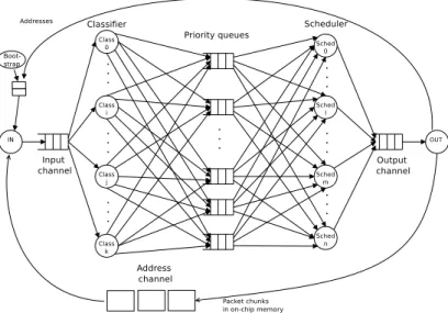
The task and communication graph shown in Figure 7 features a parallel task graph, where all tasks of a stage n can read the data output by all tasks of stage n − 1. In this application, network packets are first cut into chunks of equal size by the input co-processor. Each packet chunk has a descriptor referencing the address of the next chunk. Overall, a chunk contains a 32-bit address, 11 bits to describe its TotalSize, 20 bits date for a time stamp, and a boolean internal indicating if the packet is stored on-chip or off-chip, for a total of 64 bits. Only these descriptors are sent through the channels: indeed, packet data are kept in on-chip or off-chip memories. Note that the I/O co-processors have both, VCI and FIFO, interfaces. They also have an Ethernet interface.
The case study tasks are:
• A bootstrap task organizes the system start-up and fills the address channel with a set of addresses generated from the addresses available in packet memory.
Figure 7: Classification application: tasks and communication graph
• An input task constantly reads the addresses initially generated by the bootstrap task. Also, addresses freed from packets having left the system can be reused. Messages between bootstrap, input and output tasks corre-spond to 32-bit addresses. The Input Engine reads Ethernet encapsulated IP packets, cuts them into slots of equal size, and copies these slots to dedicated memory regions.
• A classification task reads one or several descriptors at a time, then re-trieves the first chunk of the corresponding packet from memory. Any classification task can access any chunk. The helper classifiers determine the priority of each packet.
• The scheduling task reads one of the queues according to their priority order, and then writes the descriptor to the output queue. The helper schedulers schedule the packet based on its priority. Both classification and scheduling tasks use try-read primitives to start work whenever data is available and thus maximize performance.
• The output task constantly reads the output queue. Each time a slot is read, the output task frees corresponding addresses, and sends them to the address channel for reuse.
Overall, the application task graph is thus inherently cyclic and very vulnerable to buffer overflows due to contentions.
Thanks to the the latest TTool additions, we are now able to model a much more realistic version of the classification application, including bootstrap and reuse of addresses, non deterministic behavior, I/O operations and monitor of the fill state of channels. Abstraction is made from the actual classification
and scheduling algorithms, where they are replaced by minimum and maximum computation time.
5.1. Modeling at Partitioning Level
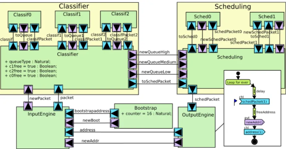
Figure 8 shows the design of the application at partitioning level, including the behavior of the Output Engine task. At this stage, the model focuses on the performance properties of tasks and communications. Thus, detailed algorithms and data values are abstracted to computation and transmission complexities. These abstractions facilitate the selection of a HW/SW architecture capable of executing the application.
Communications are modeled as events (in purple) or channels (in blue). Channels are used to send an amount of data, where events are used for syn-chronization. For example, the Bootstrap and Output Engine first signal to the Input Engine that they will send a new address, and wait for the Input Engine to accept before sending the address.
The data communications are modeled only in terms of their size, but not their values. We model, for example, the size of the packet sent and the size of the packets. When mapped to an architecture, the size of the data commu-nications determines if the current mapping can send the data quickly enough, or if the communications take too long to deliver, and therefore more efficient communication buses should be used.
The abstract behavior of the Output Engine is modeled in terms of its com-munications and processing complexities. As shown, the Output Engine con-tinually loops. In each loop, the Output Engine waits a certain duration before accepting a packet from the Scheduling. Once it receives a packet, it frees the corresponding address, modeled only as the processing duration at this phase. Once an address is freed, the Output Engine transmits this address to the Input Engine. The data sent and received are modeled only as a number of samples, as our abstraction level does not consider concrete values. Again, the algorithm details and exact data values are expected to be provided only in the Software Design phase, because they are not necessary to take the HW/SW partitioning decisions.
5.2. Modeling at Software Design Level
The circular nature and non-determinism of the application is also reflected in the software design model. Yet, at this level, data types become explicit and task behavior is described at a lower abstraction level.
5.2.1. Application Model
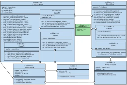
Figure 9 shows the block diagram of the telecommunication application. This architecture shows refined elements such as values exchanged via channels and extra attributes. The packet descriptor is defined as a data type called PacketDesc. The application model features three classification tasks and two scheduling tasks. This relatively low number of tasks is due to current limita-tions of the graphical representation – AVATAR diagrams cannot yet express
classif
Classif1
Classifier
Classifier
+ queueType : Natural; + c1free = true : Boolean; + c2free = true : Boolean; + c0free = true : Boolean;
Classif2 Scheduling Scheduling Sched1 Sched0 Bootstrap + counter = 16 : Natural; InputEngine OutputEngine address bootstrapaddress schedPacket newBoot newAddr newSchedPacket0 newSchedPacket1 schedPacket0 schedPacket1 toSched0 toSched1 toQueue classifPacket newQueueHigh newQueueMedium newQueueLow toSchedPacket toQueue1 toQueue2 classifPacket1 classifPacket2 newPacket classif1 classif2 packet Classif0
Loop for ever
chl schedPacket(1) evt newAddr() chl address(1) delay freeAddress
Figure 8: Functional model of the classification application
replication of identical tasks and all diagrams and automata have to be designed manually. It still permits realistic modelling of the NUMA and I/O effects; these effects are acerbated with an increasing number of tasks (up to eighty classifica-tion tasks were employed, and the channels between the Input Engine and the classification tasks had to be replicated [28]).
All logical channels between blocks are defined as asynchronous. The main communication channel is defined between Classification and Scheduling. It conveys three AVATAR signals that correspond to the three priority queues. Each priority queue (high, medium, low ) is translated into a separate multi-writer multi-reader channel in the SoCLib platform.
The upper right part of the window shows three priority queues, one for low, medium and high priority. The priority queues are modeled as asynchronous channels; their depth can be chosen, which here is set to 1024. The width is the item size (here: 8 bytes for a packet descriptor). In the example, channels are configured to be “blocking write” channels.
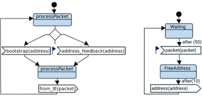
Figure 10 shows the behavior of the Input and Output Engines modeled with SysML state machine diagrams. The Input Engine first accepts addresses from the bootstrap task. The latter stops working once a preset number of addresses has been reached, at which point the Input Engine accepts addresses fed back from the Output Engine. As shown, the more detailed behavior of the Output Engine is modeled in this phase, including how addresses are freed. The after represents an estimation of the duration of the scheduling algorithm after model refinement.
The model of the classification task is rather complex. It contains three identical classification sub-tasks, which get work from the from IE channel in a task-farm manner. This task-farm way is modeled by non-deterministic choice modeled in the state Waiting. Each classification sub-task then classifies the packet, and a guarded choice operator selects the low, minimum or high priority queue. Figure 12 shows one of the inner classification tasks. Priority queues
<<block>> Scheduling - packet : PacketDesc; ~ in from_queue_low(PacketDesc packet) ~ in from_queue_medium(PacketDesc packet) ~ in from_queue_high(PacketDesc packet) ~ out to_scheduler0(PacketDesc packet) ~ out to_scheduler1(PacketDesc packet) ~ out packet(PacketDesc packet) ~ in scheduledPacket0(PacketDesc packet) ~ in scheduledPacket1(PacketDesc packet)
<<block>> Sched0
- packet : PacketDesc;
~ out scheduledPacket0(PacketDesc packet) ~ in toScheduler0(PacketDesc packet)
<<block>> Sched1
- packet : PacketDesc;
~ out scheduledPacket1(PacketDesc packet) ~ in toScheduler1(PacketDesc packet) <<block>> Classification - packet : PacketDesc; - f1 = true : bool; - f0 = true : bool; - f2 = true : bool;
~ out queue_low(PacketDesc packet) ~ out queue_medium(PacketDesc packet) ~ out queue_high(PacketDesc packet) ~ in c0_to_queue_low(PacketDesc packet) ~ in c1_to_queue_low(PacketDesc packet) ~ in c2_to_queue_low(PacketDesc packet) ~ in c0_to_queue_medium(PacketDesc packet) ~ in c1_to_queue_medium(PacketDesc packet) ~ in c2_to_queue_medium(PacketDesc packet) ~ in c0_to_queue_high(PacketDesc packet) ~ in c1_to_queue_high(PacketDesc packet) ~ in c2_to_queue_high(PacketDesc packet) ~ in from_IE(PacketDesc packet) ~ out to_c0(PacketDesc packet) ~ out to_c1(PacketDesc packet) ~ out to_c2(PacketDesc packet)
<<block>> Classif2
- packet : PacketDesc; ~ out to_queue_low(PacketDesc packet) ~ out to_queue_medium(PacketDesc packet) ~ out to_queue_high(PacketDesc packet) ~ in from_classif(PacketDesc packet)
<<block>> Classif1
- packet : PacketDesc; ~ out to_queue_low(PacketDesc packet) ~ out to_queue_medium(PacketDesc packet) ~ out to_queue_high(PacketDesc packet) ~ in from_classif(PacketDesc packet)
<<block>> Classif0
- packet : PacketDesc; - nbPackets : int;
~ out to_queue_low(PacketDesc packet) ~ out to_queue_medium(PacketDesc packet) ~ out to_queue_high(PacketDesc packet)
~ in from_classif(PacketDesc packet) <<datatype>>PacketDesc
- address : int; - date : int; <<block>> InputEngine - packet : PacketDesc; - address : int; - frequency = 24 : int; - priority : int;
~ out packet(PacketDesc packet) ~ in address(int address) ~ in bootstrap(int address) <<block>> OutputEngine - packet : PacketDesc; - address : int; ~ out address(int address) ~ in packet(PacketDesc packet)
<<block>> Bootstrap
- address : int; - counter = 16 : int; ~ out address(int address)
Figure 9: Block Diagram of the classification application
behavior are modeled inside an outer classification task. Figure 11 shows the state machine diagram of the outer classification task. This model is very com-plex because we have to reflect that either we read a packet from Input Engine, dispatch it to one of the classifiers and go back to the WaitForPacket state (left hand side), or read packet already classified from one of the inner tasks and then transmit it (center) or there still may be available packets in the channels filled up by the inner tasks (right hand side).
The scheduling tasks which take up work are modeled in a similar way (Fig-ures 13 and 14). An outer task coordinates the reading from the priority queues and the writing to the output channel. The scheduling tasks are somewhat less complex because they write to a common output queue and need not contain choice operators.
5.2.2. Mapping
Allocation of tasks and channels onto the target MPSoC is explicitly cap-tured within deployment diagrams (Figure 15). These diagrams contain hard-ware nodes (e.g., CPUs and memory banks) that can be customized with param-eters such as cache associativity, memory size, network latency, etc. Software tasks are mapped onto the execution nodes of the platform, and channels be-tween tasks are mapped onto the memories.
I/O can be modeled in two ways: either as software tasks or as SoCLib models of hardware accelerators. Packet processor models are taken from [16]: one is used for reading packets from either an Ethernet connection or a file,
from_IE(packet) bootstrap(address) address_feedback(address) processPacket processPacket after (50) FreeAddress address(address) packet(packet) Waiting after(10)
Figure 10: State machines of the Input Engine and the Output Engine with latency check-points
and the other is used for writing packets after computations. The more recent network I/O facilities of SoCLib are used, allowing the reading in and analysis of Ethernet encapsulated IPv4 packets.
Timers and interrupts are not modeled in the deployment diagram because they are automatically added to the prototyping model during the generation of the SoCLib virtual platform. There are six processors in total. The target architecture features a two-level interconnect based on a Virtual Generic Micro Network (VGMN), which behaves as two independent packet switched networks for commands and responses, and two local crossbars.
6. Experiments
Parallel packet classification is known to suffer from several major perfor-mance impediments, such as overflow of the input channels for high throughput, cache misses and conflicts when taking locks, resulting in high latencies. We explore different mappings of the classification application featuring three clas-sifiers, three priority queues, and two schedulers. Compared to our previous contributions, our experimentation is no more limited to the software part of the application.
6.1. Test-bed
As we now model the (nearly) complete application, the generated platform should yield results comparable to the real one with 3 classifiers, 2 schedulers, no bursts and no packet memory access.
In the experiments, we focus on measuring latencies to analyze the perfor-mance of our system. After the Input Engine finishes reading addresses from the Bootstrap task, it reads addresses which have been liberated by the Output Engine. By inserting checkpoints in the channel leaving the Input Engine and the one entering the Output Engine, we can thus measure the processing time of such fed back addresses. Figure 10 shows the state machine diagrams annotated with latency checkpoints in the form of small flags.
Waiting WaitForPacket from_IE(packet) to_c0(packet) to_c1(packet) Waiting to_c2(packet) sendPacket [ f1] f2=false f1=false after (10,20) [ f2] [ f0] f0=false [else ] [ f0||f1||f2] Low queue_low(packet) c0_to_queue_low(packet) c1_to_queue_low(packet) c2_to_queue_low(packet) Medium queue_medium(packet) High queue_high(packet) c0_to_queue_medium(packet) c2_to_queue_medium(packet) c1_to_queue_medium(packet) c0_to_queue_high(packet) c1_to_queue_high(packet) c2_to_queue_high(packet) f0=true f2=true f1=true f0=true Waiting f0=true f1=true f2=true f1=true f2=true recQueue Low c0_to_queue_low(packet) c1_to_queue_low(packet) c2_to_queue_low(packet) Medium queue_medium(packet) High queue_high(packet) c0_to_queue_medium(packet) c2_to_queue_medium(packet) c1_to_queue_medium(packet) c0_to_queue_high(packet) c1_to_queue_high(packet) c2_to_queue_high(packet) f0=true f2=true f1=true f0=true Waiting f0=true f1=true f2=true f1=true f2=true recQueue queue_low(packet)
Figure 11: State machine of the outer classification task
6.2. Assumptions
There still are some restrictions to our model. For example, we do not model packet storage in these experiments, neither do we represent burst transfer of packet descriptors to obtain better performances. Since we are interested in general packet timing, the algorithms inside the tasks are still quite abstracted with regards to the real ones (which serve as time estimates), as we are more interested in timings rather than detailed application behavior.
6.3. Partitioning Level
Latency checkpoints are added to the Partitioning models: one is placed in the Input Engine (as soon as the bootstrap is finished and the application runs in steady state) and the corresponding one in the Output Engine (as soon as the packet is read, the after annotation reflects an estimation of the duration of the computation), as shown previously in Figure 8. This enables us to compare high-level simulation results with results obtained by cycle-bit accurate simulations. 6.4. Software Design Level
Channels are stored in memory, and the communications via these channels represent a high fraction of the application activity. When the number of tasks
to_queue_low(packet) to_queue_medium(packet) to_queue_high(packet) from_classif(packet) Classify Waiting after (20,100)
Figure 12: State machine of one of the inner classification tasks
Read to_scheduler1(packet) to_scheduler0(packet) from_queue_low(packet) from_queue_medium(packet) from_queue_high(packet) Waiting scheduledPacket1(packet) scheduledPacket0(packet) packet(packet) SendToOutput Dispatch after (50) after (50)
Figure 13: State machines of the outer scheduling task
accessing a channel increases, the amount of time spent waiting for the lock also increases.
The experiment is based on the cycle/bit accurate level of SoCLib, thus with a high level of precision, at the price of rather slow simulations. General purpose processors simulated in the virtual prototype are PowerPC 405 running at 433MHZ. The processors run the MutekH [29] micro kernel. For reading of actual Ethernet packets, we rely on the network io API provided with SoCLib. The abstract models of Input and Output Engine assume an equal part of high, medium and low priority packets, modeled by a Random operator.
In the virtual prototype, spy points —represented by magnifying glasses— correspond to hardware probes which log all transfers on the VCI interconnect. Figure 15 shows how this spy mechanism, described in [30], is now integrated in the deployment diagram. The top cell automatically generated from deployment
diagrams integrates the corresponding logger/statistics modules. The input
channel (InputEngine/out packet, spyglass 1), is mapped on the I/O cluster and accessed by the classification tasks from cluster 0. The three priority queues (Classification/out queue low, spyglass 2), mapped on Memory0, are written by
scheduledPacket0(packet) scheduledPacket0(packet) scheduledPacket0(packet) toScheduler0(packet) Waiting Enqueue PriorityHigh PriorityMedium PriorityLow [ packet.date==0] [packet.date==1 ] [packet.date==2 ]
after (100) after (50) after (10)
Figure 14: State machines of the inner scheduling tasks
<<MWMR-CoPro>> InputEngine <<MWMR-CoPro>> OutputEngine <<CROSSBAR>> Crossbar2 <<TTY>> TTY2 <<CPU>> CPU2 AVATAR Design::Classif1 <<CPU>> CPU3 AVATAR Design::Classif2 <<CPU>> CPU1 AVATAR Design::Classif0 AVATAR Design::Classification <<TTY>> TTY1 <<CPU>> CPU4 AVATAR Design::Scheduling AVATAR Design::Sched0 <<VGMN>> ICN0 <<CPU>> CPU5 AVATAR Design::Sched1 <<CROSSBAR>> Crossbar0 <<CROSSBAR>> Crossbar1 <<TTY>> TTY0 <<RAM>> Memory0 Classification/out queue_low Classif1/in from_classif Classif2/in from_classif Classif0/in from_classif 2 <<RAM>> Memory1 Sched1/in packet Sched0/in packet Scheduling/out packet Sched0/in toScheduler0 Sched1/in toScheduler1 3 <<RAM>> Memory2 Bootstrap/out address InputEngine/out packet OutputEngine/out address <<CPU>> CPU0 AVATAR Design::Bootstrap 1 4 AVATAR Design::InputEngine AVATAR Design::OutputEngine
Figure 15: Deployment Diagram with separate I/O cluster and spies (Mapping 1)
three classification tasks and read by two scheduling tasks. The output channel Scheduling/out packet, is mapped onto the scheduling cluster and monitored by spy 3, the address feedback channel (OutputEngine/out address) by spy 4. 6.5. Experimental Results
We show results for three different mappings. All take into account the results of [30] that the Scheduling/out packet channel must be mapped on the same cluster as the scheduling tasks.
1. Mapping 1 : In the mapping presented in Figure 15, three clusters are used, one for the classification tasks, one for the scheduling tasks, the final one for I/O.
2. Mapping 2 : As shown in Figure 16, I/O tasks are mapped on the classi-fication cluster. The channel containing the packet descriptors produced
<<CPU>> CPU2 AVATAR Design::Classif1 <<CPU>> CPU3 AVATAR Design::Classif2 <<CPU>> CPU1 AVATAR Design::Classif0 AVATAR Design::Classification <<TTY>> TTY1 <<RAM>> Memory0 OutputEngine/out address InputEngine/out packet Classification/out queue_low Classif1/in from_classif Classif2/in from_classif Classif0/in from_classif <<RAM>> Memory1 <<CPU>> CPU4 AVATAR Design::Scheduling AVATAR Design::Sched0 <<VGMN>> ICN0 <<CPU>> CPU5 AVATAR Design::Sched1 <<CROSSBAR>> Crossbar0 <<CROSSBAR>> Crossbar1 <<HWA>> InputEngine <<HWA>>
OutputEngine Bootstrap/out address Sched1/in packet Sched0/in packet Scheduling/out packet Sched0/in toScheduler0 Sched1/in toScheduler1 <<TTY>> TTY0 <<CPU>> CPU0 AVATAR Design::Bootstrap AVATAR Design::InputEngine AVATAR Design::OutputEngine
Figure 16: Deployment Diagram with unified I/O and classification cluster (Mapping 2)
by the Input Engine is mapped on RAM2 in the I/O cluster, whereas the channel containing the liberated addresses is mapped on RAM1 of the scheduling cluster. This choice was made because there is plenty of time left for an address to return to the input engine. Addresses are small, so buffers can thus be dimensioned with a high depth, and the latency to cross over from one cluster to another is compensated.
3. Mapping 3 : The last mapping features the same mapping as in Figure 16, except that the classification/bootstrap cluster contains an additional memory bank in order to store the address buffers (not shown).
Table 1 compares the results between the partitioning (high-level transac-tional simulation) and software design levels. On the software design level, we show results for the two variants: one where the very abstract models of Input and Output Engine are used, from which software tasks are generated, and one with the actual SoCLib models (Input Engine consisting of more than 600, the slightly simpler Output Engine of mode than 400 lines of SystemC code). The series of measurements show latencies (in milliseconds) from the reception of a new or recycled address by the Input Engine to the reception of the com-puted packet by the Output Engine (receive(address)->receive(packet)), for the three mappings. These are averages for all paths taken between the two operators in question.
We can observe that standard deviations are significant for the “end-to-end” latencies, as packet descriptors might or might not be blocked due to competition for access to a memory bank containing a channel.
Our first parameterizing of the hardware on the partitioning level actually led to an overestimation of latencies by a factor of 6 to 8 (not shown). We therefore modified our application model by reducing delay estimations to take into account the much lower latencies obtained on the virtual prototype. The columns Partitioning show latencies after these corrections. For the latencies measured in Software Design, however, the second mapping demonstrates the worst performance, which is not observed in the Partitioning evaluations.
The rightmost three columns of Table 1 show increasingly realistic virtual prototypes, the rightmost obtained with the original one from [30], featuring
handwritten C Posix code for these tasks. When replacing the Input and Out-put Engine generated from the abstract description by the cycle-bit accurate (caba) models, we note a slight increase of latencies, thus would have revise the abstract models shown in Figure 10 and add delays in order to be closer to the more realistic model. We finally compare our prototypes, where the code of the classification and scheduling tasks is generated from timed automata, hand-written C Posix code for these tasks, for the same configuration and number of tasks and channels (rightmost column).
It should be noted that we do not model packet memory, thus have fewer source of contention when accessing the memory bank, and thus a slight advan-tage wrt. the original application. The results obtained with SoCLib models of the I/O co-processors are clearly closer to the results for the complete system with handwritten Posix tasks.
However, while a simulation on partitioning level is performed in a mat-ter of seconds, the full-system simulation of the platform takes several hours (execution of the bootstrap and transmitting 10k packets of random priorities) even with a relatively small number of tasks. As shown in [2] where we focused
on throughput, in the 20 million simulation cycles after bootstrap 3.5 ∗ 10−5
bytes are transferred per simulation cycle. With the cycle-bit accurate models of the I/O engines, simulation time remains practically unchanged: the num-ber of transfers on the VCI interconnect dominates the time for cycle accurate simulation of I/O engines. Transfers initiated by software running on CPU are replaced by the same transfers initiated by HW co-processors.
Table 1: Path Latencies
Mapping Partitioning Virtual Prototype
avg std dev abstract I/O HW I/O original
Mapping 1 18.6 12.2 10.1 12.7 14.8
Mapping 2 19.2 11.1 13.0 15.6 17.2
Mapping 3 17.9 11.2 10.5 12.9 14.4
6.6. Latency Feedback on diagrams
As was mentioned in section 4.1, latencies are annotated and eventual de-viations reported. Figure 17 shows an example of latency annotations on the software design level (the signal is internally numbered 752). In the example, we measured an average latency of 327 microseconds from the reception of a address by the Input Engine to the reception of this address by the Output Engine.
6.7. Discussion
Due to current restrictions on the number of tasks which can be represented in TTool diagrams, the number of tasks is small, but still sufficient to demon-strate the effects of contention. In previous work on the same application, the
packet(packet) Receive signal-address:752 327 Waiting address(address) FreePacket after (50) after (10)
Figure 17: Feedback of latencies in the Output Engine
effects shown here were exacerbated as experiments were performed for dozens of classification tasks, mapped to several different clusters and thus creating even higher contention on the interconnect.
An important advantage of working with a graphical interface like TTool is that the rather important structural modifications between the mappings (pass-ing from three to two clusters and redistribut(pass-ing channels) took less than five minutes. In the original exploration, shell scripts could impact only the num-bers of tasks and memory banks, so such structural changes of the underlying hardware would require a rewriting of the top-cell.
What we are still lacking is the determination of latencies for individual packets. In order to obtain this, an identifier has to be inserted into the de-scriptor by the Input Engine and extracted by the Output Engine. We could also gain more precise results on the Software design level by inserting actual C Posix code into the description by timed automata —for this purpose, AVATAR features a prototyping option— but this would mean that generated application code is no longer correct by construction.
7. Conclusion and Future Work
This paper extends a UML/SysML virtual prototyping environment with new modeling and evaluation capabilities for streaming applications. We first explain the necessary extensions: modeling extensions, semantics extension, and code generation extensions. We then show how these extensions have been integrated into TTool. We also demonstrate how performance metrics such as latency can be estimated, then measured, on models spanning different levels of abstraction.
An exhaustive case study shows the modeling and experimental results for an application that is particularly difficult to handle by regular tools: high per-formance packet classification. We obtain a generated platform and application very close to the original, handwritten one by extending TTool to handle the new aspects: task-farm, NUMA, I/O.
High performance streaming applications such as the one analyzed in the case study usually feature a larger number of tasks; we will thus require the ability to describe and automatically generate multiple identical tasks, and to generate code for these tasks accordingly. As shown for the example featuring three classification and two scheduling tasks, the complexity for obtaining a semantically correct model is high and, for larger numbers of tasks, near impos-sible to model by hand.
Other typical I/O co-processors should be made available in the deployment diagrams of TTool. The problem is that such components are very specific and corresponding SoCLib models do not always exist. The generation of virtual co-processors on different degrees of abstraction, starting at partitioning level, thus is another interesting and important issue.
Our long term work targets full design space exploration. Even if currently re-mapping is only semi-automatic and requires the designer to manually adapt the architecture and the mapping, the level of abstraction allows for changes to be made quickly and easily. More importantly, profound structural changes are modeled and reflected in the virtual prototype in a matter of minutes.
References
[1] D. Genius, L. Apvrille, System-level design for communication-centric task farm applications, in: 12th International Symposium on Reconfigurable Communication-centric Systems-on-Chip, IEEE, 2017, pp. 1–8.
[2] D. Genius, L. Apvrille, System-level design and virtual prototyping of a telecommunication application on a numa platform, in: 2018 13th Interna-tional Symposium on Reconfigurable Communication-centric Systems-on-Chip, IEEE, 2018, pp. 1–8.
[3] A. Kumar, A. Hansson, J. Huisken, H. Corporaal, Interactive presenta-tion: An fpga design flow for reconfigurable network-based multi-processor systems on chip, in: Proc. DATE’07, EDA Consortium, 2007, pp. 117–122. [4] K. Goossens, B. Vermeulen, A. B. Nejad, A high-level debug environment for communication-centric debug, in: Proc. DATE’09, 2009, pp. 202–207. [5] J. Eker, J. W. Janneck, E. A. Lee, J. Liu, X. Liu, J. Ludvig, S. Sachs,
Y. Xiong, S. Neuendorffer, Taming heterogeneity - the Ptolemy approach, Proceedings of the IEEE 91 (1) (2003) 127–144.
[6] P. Lieverse, P. van der Wolf, K. A. Vissers, E. F. Deprettere, A methodol-ogy for architecture exploration of heterogeneous signal processing systems, VLSI Signal Processing 29 (3) (2001) 197–207.
[7] F. Balarin, Y. Watanabe, H. Hsieh, L. Lavagno, C. Passerone, A. L. Sangiovanni-Vincentelli, Metropolis: An integrated electronic system de-sign environment, IEEE Computer 36 (4) (2003) 45–52.
[8] C. Erbas, S. Cerav-Erbas, A. D. Pimentel, Multiobjective optimization and evolutionary algorithms for the application mapping problem in multipro-cessor system-on-chip design, IEEE Evol. Comp. 10 (3) (2006) 358–374. [9] G. Kahn, The semantics of a simple language for parallel programming, in:
J. L. Rosenfeld (Ed.), Information Processing ’74: IFIP Congress, North-Holland, New York, NY, 1974, pp. 471–475.
[10] A. D. Pimentel, L. O. Hertzberger, P. Lieverse, P. van der Wolf, E. F. Deprettere, Exploring embedded-systems architectures with artemis, IEEE Computer 34 (11) (2001) 57–63.
[11] J. Vidal, F. de Lamotte, G. Gogniat, P. Soulard, J.-P. Diguet, A co-design approach for embedded system modeling and code generation with UML and MARTE, in: DATE’09, 2009, pp. 226–231.
[12] A. Gamati´e, S. L. Beux, ´E. Piel, R. B. Atitallah, A. Etien, P. Marquet,
J.-L. Dekeyser, A model-driven design framework for massively parallel embedded systems, ACM TECS 10 (4) (2011) 39.
[13] M. Di Natale, F. Chirico, A. Sindico, A. Sangiovanni-Vincentelli, An MDA approach for the generation of communication adapters integrating SW and FW components from simulink, in: MODELS’14, 2014, pp. 353–369. [14] G. Batori, Z. Theisz, D. Asztalos, Domain specific modeling methodology
for reconfigurable networked systems, in: G. Engels, B. Opdyke, D. C. Schmidt, F. Weil (Eds.), MODELS’07, Springer, 2007, pp. 316–330. [15] D. Comer, L. Peterson, Network Systems Design Using Network Processors,
1st Edition, Prentice-Hall, Inc., Upper Saddle River, NJ, USA, 2003.
[16] S. Berrayana, E. Faure, D. Genius, F. P´etrot, Modular on-chip
mul-tiprocessor for routing applications, in: M. Danelutto, M. Vanneschi,
D. Laforenza (Eds.), Euro-Par, Vol. 3149 of Lecture Notes in Computer Science, Springer, 2004, pp. 846–855.
[17] L. Apvrille, Webpage of TTool, in: http://ttool.telecom-paristech.fr/. [18] D. Genius, L. W. Li, L. Apvrille, Model-Driven Performance Evaluation
and Formal Verification for Multi-level Embedded System Design, in:
Con-fer´ence on Model-Driven Engineering and Software Development, Porto,
Portugal, 2017.
[19] G. Pedroza, D. Knorreck, L. Apvrille, AVATAR: A SysML environment for the formal verification of safety and security properties, in: NOTERE, Paris, France, 2011.
[20] L. Apvrille, L. W. Li, Harmonizing safety, security and performance require-ments in embedded systems, in: Design, Automation and Test in Europe (DATE’2019), Firenze, Italy, 2019.
[21] J. Bengtsson, W. Yi., Timed automata: Semantics, algorithms and tools, in: Lecture Notes on Concurrency and Petri Nets, W. Reisig and G. Rozen-berg (eds.), LNCS 3098, Springer-Verlag, 2004, pp. 87–124.
[22] B. Blanchet, Modeling and Verifying Security Protocols with the Applied Pi Calculus and ProVerif, Now Foundations and Trends, 2016.
[23] D. Genius, L. Apvrille, Virtual yet precise prototyping: An automotive case study, in: ERTSS’2016, Toulouse, 2016.
[24] SoCLib consortium, SoCLib: an open platform for virtual prototyping of multi-processors system on chip (webpage), in: http://www.soclib.fr. [25] VSI Alliance, Virtual Component Interface Standard (OCB 2 2.0), Tech.
rep. (Aug. 2000).
[26] E. Faure, A. Greiner, D. Genius, A generic hardware/software communica-tion mechanism for multi-processor system on chip, targeting telecommuni-cation applitelecommuni-cations, in: ReCoSoC, Montpellier, France, 2006, pp. 237–242. [27] D. Genius, L. W. Li, L. Apvrille, Multi-level Latency Evaluation with an MDE Approach, in: Conference on Model-Driven Engineering and Software Development, Funchal, Portugal, 2018.
[28] D. Genius, E. Faure, N. Pouillon, Mapping a telecommunication application on a multiprocessor system-on-chip, in: G. Gogniat, D. Milojevic, A. M. A. A. Erdogan (Eds.), Algorithm-Architecture Matching for Signal and Image Processing, Springer LNEE vol. 73, 2011, Ch. 1, pp. 53–77.
[29] A. Becoulet, Mutekh, http://www.mutekh.org.
[30] D. Genius, Measuring Memory Latency for Software Objects in a NUMA System-on-Chip Architecture, 8th International Symposium on Recon-figurable Communication-centric Systems-on-Chip, Darmstadt, Germany, 2013.
![Figure 1: Overall Approach from [18]](https://thumb-eu.123doks.com/thumbv2/123doknet/11646157.307821/6.918.207.714.188.468/figure-overall-approach-from.webp)

![Figure 5: Relation between latencies in Partitioning and Software Design Models from [27]](https://thumb-eu.123doks.com/thumbv2/123doknet/11646157.307821/10.918.300.617.265.626/figure-relation-latencies-partitioning-software-design-models.webp)