HAL Id: hal-03121013
https://hal.archives-ouvertes.fr/hal-03121013
Submitted on 26 Jan 2021
HAL is a multi-disciplinary open access archive for the deposit and dissemination of sci-entific research documents, whether they are pub-lished or not. The documents may come from
L’archive ouverte pluridisciplinaire HAL, est destinée au dépôt et à la diffusion de documents scientifiques de niveau recherche, publiés ou non, émanant des établissements d’enseignement et de
Study of post-impact behaviour of thin hybrid
carbon/epoxy and glass/epoxy woven composite
laminates under fatigue tensile loading – Part I :
Experimental study
A. Rogani, Pablo Navarro, Steven Marguet, Jean-François Ferrero, C.
Lanouette
To cite this version:
A. Rogani, Pablo Navarro, Steven Marguet, Jean-François Ferrero, C. Lanouette. Study of post-impact behaviour of thin hybrid carbon/epoxy and glass/epoxy woven composite laminates under fatigue tensile loading – Part I : Experimental study. Composite Structures, Elsevier, 2021, 260, pp.113449. �10.1016/j.compstruct.2020.113449�. �hal-03121013�
Study of post-impact behaviour of thin hybrid
carbon/epoxy and glass/epoxy woven composite
laminates under fatigue tensile loading - Part I :
experimental study
A. Rogania,b, P. Navarroa, S. Margueta, J-F. Ferreroa, C. Lanouetteb aUniversit´e de Toulouse, Institut Cl´ement Ader, FRE CNRS 3687,
UPS/INSA/ISAE/Mines Albi, 3 rue Caroline Aigle, 31400 Toulouse, France
bAirbus Helicopters, 1 Place du G´en´erale Val´erie Andr´e, 93440 Dugny, France
Abstract
This article concerns the experimental study of post-impact damage propa-gation in two thin carbon/epoxy and glass/epoxy hybrid woven composite laminates loaded in fatigue tension. Low velocity normal drop weight impact tests are first performed. Post-impact fatigue tensile tests are then carried out. They are controlled in displacement. The damage propagation is mon-itored by RX Tomography and Digital Image Correlation. The influence of the impact energy and the displacement level variation on the post-impact damage propagation is studied. Post-impact fatigue tests are also conducted on thin carbon/epoxy and glass/epoxy mono-material woven composite lam-inates in order to understand the phenomenons which occur in the hybrid laminates. Two different behaviours depending on the hybrid configuration are obtained. The post-impact damage propagation in fatigue is mainly in-fluenced by the the carbon plies orientations. Levels of loading and impact energies have an influence on the initiation of the damage propagation and on the speed. They have also an influence of the damage propagation
sce-nario when delamination occurs. The influence of the stacking sequence is also studied. The change of the carbon plies position in the hybrid laminate leads to a change of the post-impact fatigue behaviour.
Keywords: Fatigue, Woven composites, thin laminates, hybrid laminates, post-impact behaviour, digital image correlation, RX tomography
1. Introduction
This two-parts article deals with the post-impact behaviour of helicopter blades composite skins under fatigue tensile loading. Indeed, these skins are generally thin hybrid carbon/epoxy and glass/epoxy woven composite laminates that can be impacted in flight and that are mainly loaded in ten-sion. In this paper fatigue tests are performed on hybrid woven composite samples after having been impacted with a low velocity. Tests are also con-ducted on mono-material woven composite samples in order to understand the phenomenons occurring in the hybrid samples.
Carbon and glass woven composite structures are widely used, especially in the field of aeronautics. However, these structures are known to be very sensitive to impact loadings. In fact, an impact can generate matrix cracking, delamination and fibre breakage. The impact can perforate the structure or the damages can be barely detectable. In any case, that induces a decrease of the mechanical properties and a loss of the strength. The impact damage can also propagate when a load is applied to the structure. It can lead to the final failure of the structure and have dramatic consequences.
For all these reasons, understanding and identifying the post-impact dam-age propagation phenomenons which occur in a carbon/glass hybrid woven composite structures subject to a fatigue tensile loading is important.
In general, studies on composite structures are typically conducted at a macroscopic scale in order to obtain the residual mechanical properties of the laminate such as the residual strength [1, 2, 3, 4, 5], the residual strain or the residual stiffness [6]. Other authors try to characterize the material through the establishment of a Wohler curve [5]. The visualization of the
damage propagation is sometimes performed at a microscopic scale.
Studies are mainly performed in compression-compression [7] or tension-compression [8, 9, 10, 11]. In fact, the delamination, generated by impact and subject to compression loading, can provoke local buckling that could lead to an unstable propagation of the damage [12]. For instance, Melin et al. [8] concluded that during tension-compression fatigue loading on impact damaged carbon/epoxy samples, the compressive part of the cycle had a more important role in failure than the tensile part. And, Beheshty et al. [7] noticed that the effects of impact damage on carbon/epoxy laminates were more severe for compression-compression fatigue loading than for tension-compression loading. Kimpara et al. [10] realized tension-tension-compression fa-tigue test on carbon/epoxy woven laminates impacted at 1 J with a drop weight device. They have noticed, for N/Nf = 0.9, a sudden failure located
in the impact area without any precursor signs, multiples transverse crackings and a delamination propagation through the thickness, initiated at the tip of these crackings. Then, due to a stress concentration, crackings initiate also at the tip of the delaminations. For a carbon woven [0◦/±45◦]
3s, also subject
to tension-compression fatigue loading, Garnier et al. [11] have studied the damage propagation with infrared thermography. The damage propagates in three phases : a fast propagation of the damage at the beginning of the test in the two directions of the plan, then a stabilization and finally a quick evolution only in the perpendicular direction of the loading.
Several techniques are used in the literature to follow the damaging during the fatigue test. For example, Digital Image Correlation (DIC) [14, 15, 16, 17], acoustic emission [18, 19], self-heating methodology [20] or C-scan [9, 10].
Ambu et al. [14] monitored their tension-tension fatigue tests on CFRP samples with digital image correlation. They found that DIC was a useful to identify the roles and the influence of each failure modes on the residual properties of notched samples, the mechanisms of damage development and the strain distribution around a hole. DeRosa et al. [19] made a correlation between the amplitude of acoustic emission and the type of damage occurring in the laminate. Gornet et al. [20] made a link between heating effects and damage mechanisms during fatigue loading.
Concerning the specific case of tensile fatigue behaviour of woven com-posites after having been impacted, only few studies have been found in the litterature. Cantwell et al. [1] have shown that substituting UD carbon plies by woven plies in a laminate improved the fatigue behavior of the composite structure. The residual strength less decreases and the damages propagate much slower. However, through a similar study on carbon woven laminate [0◦]
10, Ding et al. [2] indicated that the increase of the impact energy lead to
a decrease of the residual strength of the laminate. It is more pronounced for carbon woven oriented at ±45◦ that 0◦ [4]. The residual stiffness decreases
also with the impact energy [6]. It decreases in three steps : an initial fast decrease, a stable state which indicates the beginning of the transverse crack-ing and a final fall just before the failure. The higher is the stress level, the higher is the number of cycles necessary to reach a stable state. Hansen et al. [21] performed fatigue tension of a non-visible post-impact damage in a glass/epoxy woven laminate. For low levels of load, the damage does not propagate. The sample failure occurs in the tabs as in quasi-static tension. When the stress level increases, damaging initiates at the impacted area.
The propagation propagates slowly in the transverse direction of the loading and suddenly speeds up just before the final failure of the laminate.
The work presented in this paper aims at completing these studies. In-deed, a special focus is made on the fatigue post-impact behaviour of hybrid glass/epoxy and carbon/epoxy woven composites under tensile cycling load-ing. More, it also describe an original method for the monitoring of damages based on DIC and X-Ray tomography. Finally, the last purpose of the ex-perimental study presented here is to be used for the development and the validation of the numerical FEM modelling that is presented in part II.
To do so, the post-impact damage propagation in two carbon/epoxy and glass/epoxy thin hybrid woven composite laminates under fatigue tensile loading is presented. In parallel, tests are also conducted on glass/epoxy and carbon/epoxy woven laminates in order to identify and analyze the propaga-tion phenomenons in the two hybrid laminates. The influence of the stacking sequence is also studied. Low velocity impacts are first performed with a drop weight device and fatigue tensile tests are carried out on the impacted samples. Impact energies and levels of solicitation are varied. The moni-toring of the damage propagation is based on measures from Digital Image Correlation and RX tomography.
The post-impact damage propagation is influenced by the glass ply and by the orientation of the carbon plies. The glass ply elongation is monitored by the carbon plies. Levels of loading and impact energies have an influence of the fatigue damage initiation and speed. The damage propagation scenario is also influenced by delamination.
2. Material and samples 2.1. Materials
In this study, the post-impact fatigue tensile behaviour of two thin hybrid carbon/epoxy and glass/epoxy woven composite laminates typically used for helicopter blade skins is investigated. These configurations, presented in Table 1, are made with plies of different materials : G0C45C45 is made up of one glass ply oriented at (0/90)◦ and two carbon plies oriented at ±45◦,
G0C45C0 is made up of one glass ply oriented at (0/90)◦, one carbon ply
oriented at ±45◦ and one carbon ply oriented at (0/90)◦.
The mono-material configurations tested to understand the phenomenons occurring in the hybrid laminates are given in Table 2. They are parts of the hybrid laminates : C0C0 is made up of two carbon plies oriented at (0/90)◦,
C45C45 is made up of two carbon plies oriented at ±45◦ and G0G0 is made
up of two glass plies oriented at (0/90)◦.
For the glass plies, (7781/913) woven fabric prepreg provided by Hexcel is used. The fiber volume fraction is 37% and the surface weight is 303 g.m−2.
For the carbon plies, (G963/913) woven fabric prepreg provided by Hexcel is used. The fiber volume fraction is 46% and the surface weight is 285 g.m−2.
The samples were cured three hours at 135◦C in a press with heaten platen.
2.2. Sample
The sample has been chosen to perform both low velocity impact test and fatigue tensile test (Figure 1). The dimensions are 100 mm x 300 mm with a thickness of 1.02 mm for G0C45C45/G0C45C0, 0.71mm for C0C0/C45C45
and 0.62 mm for G0G0. The tabs are made with three plies of glass/epoxy woven oriented at ±45◦.
3. Low velocity impact tests
The study is performed in two steps. First, the damage is generated by impact and then the fatigue tensile tests are carried out. The impact tests have already been realized in a previous study in order to investigate the behaviour of the laminates under post-impact quasi-static tension [22]. They have been performed with a drop weight device presented on the Figure 2. The impactor has a 16 mm diameter hemispherical steel head with a mass of 2 kg. Several impact energies have been performed (Table 3).
The fracture surfaces of the impacted hybrid samples are presented on the Figures 3 and 4. The values in yellow represents the size of the damaged area in the upper ply and the values in white represent the size of the fibres breakages in each ply.
For the G0C45C45 configuration, a small damage is observed for an en-ergy of 2.25 J. Fibre breakages are observed in the lower ply and the resin of the upper ply is damaged. Then, the damage increases until 6.25 J. Fibres breakages are observed in the upper ply for the impact energy of 4 J. Finally for the 9 J and 16 J tests, the impactor perforates the three plies so that a similar damage size for the two impacts is measured.
These observations are the same for the G0C45C0 configuration : fibres breakages and resin damage start to be significant for 4 J. The fibres break-ages appear in the lower carbon ply at 2.25 J and in the glass ply at 4 J. Damage sizes increase with the energy of impact. For 9 J and 16 J, the
impactor completely perforates the laminate and the damages are almost identical.
In order to be as complete as possible, the fracture surfaces of the im-pacted mono-material samples are presented on the Figures 5,6 and 7. 4. Fatigue tensile tests on impacted samples
Fatigue tensile tests are carried out with an INSTRON machine with a load cell of 250 kN (Figure 8). In order to represent the cyclic loading of the blade in flight, these tests are controlled in displacement. The imposed cycle is presented on the Figure 9. A quasi-static rise is imposed until ∆Lsta
and a cycle of half-amplitude ∆Ldyn is imposed with a frequency of 15 Hz.
The load ratio is defined as R = ∆Ldyn/∆Lsta = 0.9. The level of the fatigue
load is set as a function of the break displacement in quasi-static tension ∆Lrupt QSmeasured in [22] : ∆Lsta= 25% ∆Lrupt QSfor G0C45C45 and ∆Lsta
= 40% ∆Lrupt QS for G0C45C0. The levels for the mono-material laminates
are chosen with the same method and set to : ∆Lsta = 25% ∆Lrupt QS for
G0G0/C45C45 and ∆Lsta = 40% ∆Lrupt QS for C0C0.
The influence of impact energy and fatigue cycle amplitude level on the post-impact damage propagation is studied through the values presented in Table 4.
The reaction load is measured during the test. The strain fields in the upper and lower plies are monitored by the use of Digital Image Correlation (DIC). To do so, two cameras are placed at each side of the sample to take images at chosen time interval (Figure 8).
in [15, 16, 17] , the value of the correlation quality factor Sigma can be used : it increases when damage appears in the ply. More, RX tomography is used to observe and measure the internal damages that can not be observed with the previous method. To do so, tests are stopped at different number of cycles.
4.1. Results
4.1.1. Configuration G0C45C45
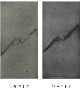
For the configuration G0C45C45, the final fracture surface is the same whatever the impact energy and the displacement level. The post-impact damage propagates at ±45◦ in the three plies (Figure 10).
RX tomography after the fatigue loading shows that the glass ply is bro-ken but not the carbon plies (Figure 11). Warp and weft bundles breakages are noticed in the glass ply while tows/resin splittings and intra-tows crack-ings are noticed in the carbon plies.
Curves representing the reaction load versus the number of cycles are given in Figure 12. The drop of load observed on the curves corresponds to the breakage of the glass ply.
Finally, the behaviour of an impacted sample of configuration G0C45C45 is similar if it is subject to a fatigue or a quasi-static tensile loading [22, 23]. The main difference is that contrary to quasi-static loading, the damage propagation in the glass ply in fatigue is progressive.
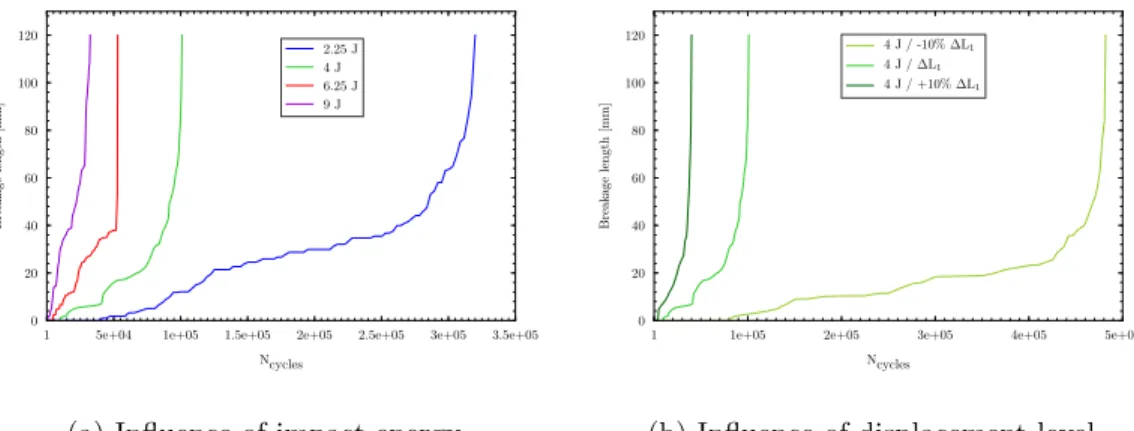
Whether the impact energy or the displacement level, the evolutions of the fibres breakages length in the glass ply are similar (Figure 13). The curve representing the damage length depending on the number of cycles can be
decomposed into three parts : first the initiation of the propagation, then a progressive evolution and finally a fast propagation when the damage comes closer to the edges samples. However, the last part of the evolution is due to a structural effect and is not representative of the damage propagation.
The influence of the impact energy and the displacement level is notice-able on the number of cycles necessary to initiate the fibres breakages in the glass ply and on their propagation speed. Table 5 shows that the increase of the impact energy or of the displacement level leads to a decrease of the number of cycles for the initiation of fatigue damage and for the glass ply failure. It also leads to a decrease of the gap between the initiation and the failure.
The observation of the strain field in the loading direction εyy around the
damage area at the beginning of the fatigue test obtained by DIC can explain this influence (Figure 14).
The strain value is more important with the increase of the impact energy. Thus, the fibres are more loaded in tension and the first breakage appears faster.
These values converge when the impact energy increase. It can be ex-plained by the fact that the impact damage size increases until a maximum size that corresponds to the perforation of the sample.
4.1.2. Configuration G0C45C0
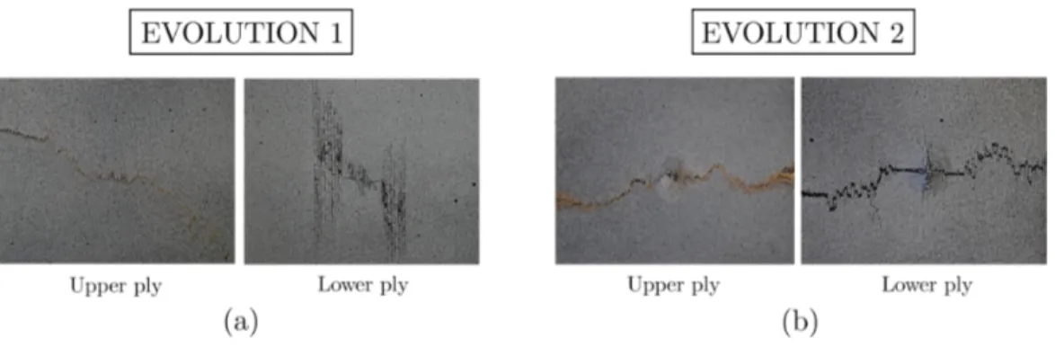
For the configuration G0C45C0, the fracture surface obtained after fa-tigue tensile test on impacted sample are given on the Figure 15. Two dif-ferent fracture surfaces are observed according the impact energy and the
displacement level (Figure 16) :
1. For low impact energies or low displacement levels, a first damage evo-lution is obtained. The upper glass ply is broken at ±45◦. The lower
carbon ply is not broken but vertical matrix cracks are observed in this ply. The tests can continue a long time without the complete failure of the laminate : concerning the results of the Figure 15, the tests of the unbroken laminates have been stopped at 3.106 cycles
2. For high impact energies or high displacement levels, a second damage evolution is obtained. The three plies are completely broken. The damage propagation starts at ±45◦ and finishes horizontally. In this
case, the failure of the sample is very fast : the number of cycles are lower than 100 000.
A transition between these two damage evolutions is noticeable for the couple (∆L2 ; 6.25 J). Indeed, the two evolutions have been obtained for this
test configuration.
The difference of the two damage scenario are also noticeable on the load curves (Figure 17). For the evolution 2, the failure of the sample is represented by the fast fall of load. The number of cycles necessary to break the laminate decreases with the increase of the impact energy and of the loading level. In fact, as for G0C45C45, this evolution is identical to the one obtained in quasi-static tension in [22, 23]. It is governed by fibres breakages. The post-impact damage propagation begins with warp and weft bundles breakages at ±45◦ respectively in tension and compression in the
glass ply. Then, fibres breakages start to propagate in the lower carbon ply also at ±45◦. The final failure occurs when the fibers of the middle carbon
ply start to break. Thus, with a fatigue loading, if the post-impact damage size or loading level are increased, these fibers break sooner.
For the evolution 1, the load decreases progressively. It is due to the progression of the post-impact damage in the sample. Figure 18 presents the damage propagation observed by RX tomography. Fibres breakages propa-gate at ±45◦ in the glass ply. Vertical matrix damaging propagates in the
lower carbon ply. Delamination propagates between the two carbon plies. If the number of cycles increases, the fibres breakages in the glass ply reaches the edges of the sample. Furthermore, delamination growths and the matrix damage in the lower carbon ply progresses vertically but also horizontally. 4.2. Discussion
4.2.1. Comparison with mono-material laminates
In the following, the only purpose of the comparisons between the hybrid configurations and mono-material configurations is to analyze the mecha-nisms leading to the propagation of the damage. Indeed, as the thicknesses are different, a quantitative comparison is impossible.
First of all, the behaviour observed for G0C45C45 configuration is ana-lyzed by comparing with what observed with C45C45 and G0G0 samples.
For the configuration C45C45, the post-impact damage propagates at ±45◦ (Figure 19). RX tomographies realized after fatigue loadings indicate
no presence of fibers breakages but the development of two types of matrix damaging : tow/resin splittings and intra-tows crackings (Figure 20). The damage monitoring based on DIC indicates that the propagation initiates with tows/resin splittings from each tip of the initial fibres breakages. They
progress transversely to the initial breakages in order to join into a unique point. Then, they propagate at ±45◦ from the point of intersection and
intra-tows crackings initiate. These two types of matrix damaging propagate at ±45◦ but the intra-tows crackings propagation is much slower.
For the configuration G0G0, DIC shows that the principal strain direc-tion at the tip of the damage is oriented in the loading direcdirec-tion (Figure 21). That indicates a damage propagation governed by fibres breakages. Their evolution depends on the number of cycles and can also be decomposed into three parts with the same structural effect as the one observed above (Fig-ure 22).Contrary to what observed on the glass ply of G0C45C45 configura-tion, the crack is oriented perpendicular to the loading and not at ±45◦.
Thus, for G0C45C45 configuration, the damage propagation behaviour is mainly monitored by the behaviour of the two carbon plies. Indeed, the strain in the glass ply are influenced by the by the deformation of the C45 plies and that is why the observed crack is oriented at ±45◦.
Second of all, the damage propagation observed for G0C45C0 configu-ration is analyzed with the help of damage propagation results on C0C0 samples. Indeed, the vertical damage propagation observed in the lower car-bon ply oriented at (0/90)◦ is explained by the observations made during a
fatigue tensile test on an impacted sample of configuration C0C0. Indeed, in this case, the post-impact damage also propagates vertically (Figure 23).
The DIC indicates the presence of vertical areas strongly loaded in shear (Figure 24). The damage propagates into this areas and is governed by resin damaging. In fact, RX tomography shows the emergence of tows/resin splittings and intra-tows crackings.
From these observations, the evolution 1 of the post-impact damage in fa-tigue tension in the hybrid laminates G0C45C0 can be described : tows/resin splittings and intra-tows crackings propagate vertically in the lower carbon ply and delamination propagates between the two carbon plies. This delam-ination dissociates the carbon plies. Thus, the elongation of the glass ply is only monitored by the elongation of the middle carbon ply oriented at ±45◦.
That leads to a propagation at ±45◦ of fibres breakages in the glass ply as
for the configuration G0C45C45. Once the glass ply is broken, damage prop-agation in the middle ply stops, and resin damaging in the lower carbon ply continue to propagate vertically and horizontally.
The curves on Figure 17 show that the load decreases faster i.e the damage propagation accelerates with the increase of the impact energy or the loading level. For instance, Figure 25 presents the damage in the upper and lower plies at 500 000 cycles for several impact energies and displacement levels. An increase of these levels leads to a more important propagation of fibres breakages in the glass ply and a more developed matrix damage in the vertical and horizontal directions in the lower ply. More, the number of cycles at the glass ply failure decrease with this increase (Table 6).
The change of the post-impact damage scenario is obtained by an increase of the impact energy (post-impact damage size) or the displacement level. In fact, the fibres in the lower carbon ply are more loaded in tension at the beginning of the tensile fatigue test (Figure 26). Their breakage leads to the evolution 2 with a fast and simultaneous propagation of fibres breakages in each ply as in quasi-static.
4.2.2. Influence of the stacking sequence
For the laminate G0C45C0, the influence of the stacking sequence on the post-impact fatigue behaviour is studied. Indeed, during impact on thin laminates, the ply opposite to the impacted face is the most damaged. In this purpose, the order of the two carbon plies is reversed. The new studied configuration is G0C0C45. Three impact energies are investigated : 2.25J / 4J / 16J at fixed displacement. Three displacement levels are also tested for an impact energy of 4J.
First of all, the damage obtained by drop weight impact tests have similar sizes between the two laminates (Figure 27). Nevertheless, the C45 ply is most damaged as it is at the opposite of the impacted side. It has an influence on the post-impact damage propagation in fatigue. The fracture surfaces are given on the Figure 28. For samples initially impacted at 2.25J and 4J and subjected to the lower imposed displacement, the sample failure never occurs. Testings have been performed until 4.106 cycles. But, the final failure takes
place for higher impact energy and displacement. For the sample initially impacted at 16J, failure occurs quasi-immediately and the fracture surface is identical to those obtained in quasi-static tension (Figure 29a). For higher imposed displacement, the failure is not sudden. The speed of the damage propagation increases with the increase of the imposed displacement and the fracture surface is identical to those obtained in quasi-static tension for the laminate C45C0 (Figure 29b).
For 2.25J and 4J, the sample visualization after the fatigue loading and RX tomography indicates that matrix damaging and compressive breakages of weft bundles propagate vertically in the glass ply, matrix damages
propa-gates at ±45◦ in the lower carbon ply and delamination progresses between
the glass ply and the middle carbon ply (Figure 30). In this case, the increase of the impact energy leads to a faster damage propagation. The vertical propagation of the damage in the glass ply indicates that, as for the lami-nate G0C45C0, the glass ply elongation is monitored by the middle carbon ply. Thus, the change of the stacking sequence modifies the damage propa-gation scenario in the glass ply. In fact, the load curves show that the final failure of the glass ply never occurs for these samples (Figure 31).
For the sample subjected to higher displacements, the damage propaga-tion starts in the same way (Figure 32). Vertical damaging propagates in the glass ply and damaging oriented at ±45◦ propagates in the lower carbon
ply. However, during the fatigue loading, the fibers, located at the edge of the impacted area, are more and more loaded in tension. That leads to a propagation of fibers breakages in the three plies. These initiation and prop-agation occur during a very brief period of time. Indeed, the load curves indicate that the sample loaded with a displacement level -10% ∆L3 behaves
as the sample loaded with a displacement level -5% ∆L3 (Figure 31). The
load decreases are similar, so is the degradation of the laminate. The sudden fall of load, corresponding to the final failure of the laminate, occurs without any preliminary signs of a damage acceleration.
Contrary to the configuration G0C45C0, for G0C0C45, only vertical fibers breakages develop in the glass ply. So, during the fatigue loading, for high imposed displacements, the strains do not locate at the tip of the glass fibers breakages. But, due to the delamination between the glass ply and the middle carbon ply, they locate in the middle carbon ply at the edge of the
post-impact damage (Figure 32). Thus, fibers breakages initiate in this carbon ply. That leads to the sudden failure of the laminate with a fracture surface similar to that observed in quasi-static for the configuration C45C0.
4.2.3. Summary
The analysis of the experimental observations of the post-impact damage propagation under tensile fatigue loading within thin hybrid woven composite laminates has led to four main results:
The behaviour of the glass ply is controlled by the carbon plies. Indeed, the glass woven fabric has a lower stiffness and it is bonded to a carbon ply. Thus the strain field in the glass ply follows the one of the carbon ply.
From a certain amount of initial damage or imposed displacement, the behaviour is the same as what have been observed with quasi-static post-impact tensile tests [22]. In fact, when the fibres are loaded more that their tensile limit, the failure of the sample is governed by the fibre breackage, which is the main failure mode observed with quasi-static loading.
Delamination can propagate with a fatigue loading, especially between two plies with different orientation. Indeed, as the C0 and C45 plies deform differently when loaded in tension, out of plane shearing appears between these plies, so that delamination can propagate in mode II. More, the experimental results show that this delamination plays an
important role in the global damage propagation mechanisms within the sample.
The stacking sequence influences the damage propagation mechanisms. Indeed, even if the samples are thin and are loaded in tension, the fact that the impact damage is not the same in each layer and that the glass ply is controlled by the middle carbon ply changes the propagation scenario.
5. Conclusion
The post-impact damage propagation in thin hybrid carbon/epoxy and glass/epoxy woven composite laminates under tensile fatigue loading has been investigated in this article. A study of the initial damage size, through the variation of the impact energy, and the level of loading has been per-formed. An analysis of the damage propagation scenario has also been carried out. This analysis is based on the study of the behaviour of mono-material laminates and the use of RX tomography and DIC. From this experimental study, three main significant results can be highlighted.
For the configuration G0C45C45, the damage propagation scenario in fatigue is identical to the one obtained in quasi-static in [22]. Whatever the impact energy or the displacement level, fibers breakages propagate at ±45◦
in the glass ply and resin damaging, compound of tows/resin splittings and intra-tows crackings, propagate at ±45◦ in the carbon plies. However, the
displacement level is not high enough to generate fibers breakages in the carbon plies.
The orientations of the carbon plies are significant. The propagation sce-nario is completely different for the configuration G0C45C0. According the impact energy or the displacement level, two scenarios are obtained. A first scenario for which the sample never completely breaks. Delamination prop-agates between the two carbon plies and comes dissociate them : tows/resin splittings and intra-tows crackings propagate vertically and horizontally in the lower carbon ply, and elongation of the glass ply is only piloted by the elongation of the middle carbon ply oriented at ±45◦. That leads to a
prop-agation at ±45◦ of fibres breakages in the glass ply as for the configuration
G0C45C45. Once the glass ply is broken, resin damaging in the lower carbon ply continues to propagate vertically and horizontally, being guided by the delamination.
Finally, the stacking sequence also has an influence on the post-impact damage propagation scenario in fatigue tension. For the configuration G0C0C45, the scenario is completely different as for G0C45C0. The glass ply elongation is piloted by the elongation of the middle carbon ply oriented at (0/90)◦. Matrix crackings and fibers breakages propagate vertically in the
glass ply, and delamination appears between the glass and carbon plies. In comparison to G0C45C0, the vertical propagation does not lead to a break of the glass ply. But, when the displacement level increases, the initiation of fibers breakages in the middle carbon ply oriented at (0/90)◦ can lead to a
sudden breakage of the laminate.
The second part of this article will be focused on the modelling of the tests studied in this part. First, numerical developments, based on the experimen-tal observations made in this part, will be presented. Then, the modelling
References
[1] W. Cantwell, P. Curtis, J. Morton, Post-impact fatigue performance of carbon fibre laminates with non-woven and mixed-woven layers, Com-posites 14 (3) (1983) 301 – 305.
[2] Y. Ding, Y. Yan, R. McIlhagger, Effect of impact and fatigue loads on the strength of plain weave carbon-epoxy composites, Journal of Mate-rials Processing Technology 55 (2) (1995) 58 – 62.
[3] K.-W. Kang, J.-K. Kim, Fatigue life prediction of impacted car-bon/epoxy laminates under constant amplitude loading, Composites Part A: Applied Science and Manufacturing 35 (5) (2004) 529 – 535. [4] K. Vallons, A. Behaeghe, S. Lomov, I. Verpoest, Impact and post-impact
properties of a carbon fibre non-crimp fabric and a twill weave com-posite, Composites Part A: Applied Science and Manufacturing 41 (8) (2010) 1019 – 1026.
[5] A. Komus, Fatigue behaviour of a barely visible impact damaged carbon fibre reinforced epoxy laminate, Ph.D. thesis, University of Manitoba (2010).
[6] D. Sudevan, R. Prakash, M. Kamaraj, Post-impact fatigue response of cfrp laminates under constant amplitude and programmed falstaff spectrum loading, Procedia Engineering 101 (2015) 395 – 403.
[7] M. Beheshty, B. Harris, T. Adam, An empirical fatigue-life model for high-performance fibre composites with and without impact damage,
Composites Part A: Applied Science and Manufacturing 30 (8) (1999) 971 – 987.
[8] L. Melin, J. Sch¨on, T. Nyman, Fatigue testing and buckling characteris-tics of impacted composite specimens, International Journal of Fatigue 24 (2) (2002) 263 – 272.
[9] N. Tai, C. Ma, J. Lin, G. Wu, Effects of thickness on the fatigue-behavior of quasi-isotropic carbon/epoxy composites before and after low energy impacts, Composites Science and Technology 59 (11) (1999) 1753 – 1762. [10] I. Kimpara, S. Hiroshi, Post-Impact Fatigue Behavior of Woven and Knitted Fabric CFRP Laminates for Marine Use, Springer Netherlands, 2010, Ch. 6, pp. 113–132.
[11] C. Garnier, M.-L. Pastor, B. Lorrain, O. Pantal´e, Fatigue behavior of impacted composite structures, Composite Structures 100 (2013) 443 – 450.
[12] G. Davies, P. Irving, 9 -, in: Polymer Composites in the Aerospace Industry, Woodhead Publishing, 2015, Ch. 9, pp. 231 – 259.
[13] T. Yuanjian, D. Isaac, Impact and fatigue behaviour of hemp fibre com-posites, Composites Science and Technology 67 (15) (2007) 3300 – 3307. [14] R. Ambu, F. Aymerich, F. Bertolino, Investigation of the effect of dam-age on the strength of notched composite laminates by digital imdam-age cor-relation, The Journal of Strain Analysis for Engineering Design 40 (5) (2005) 451–461.
[15] W. Leser, J. Newman, W. Johnston, Fatigue crack closure analysis using digital image correlation, Tech. rep., NASA (2010).
[16] M. Iadicola, T. Foecke, 2d dic crack tip tracing under mode i loading, in: Annual International DIC Society Conference, 2017.
[17] K. Conway, Multiscale behavior of fused deposition additively manufac-tured thermoplastic cellular materials, Ph.D. thesis, Clemson University (2018).
[18] C. Santulli, Post-impact damage characterisation on natural fibre re-inforced composites using acoustic emission, NDT&E International 34 (2001) 531–536.
[19] I. De Rosa, H. Dhakal, C. Santulli, F. Sarasini, Z. Zhang, Post-impact static and cyclic flexural characterisation of hemp fibre reinforced lami-nates, Composites Part B: Engineering 43 (3) (2012) 1382 – 1396. [20] L. Gornet, D. Sudevan, P. Rozycki, A study of various indicators to
determine the fatigue limit for woven carbon/epoxy composites under self heating methodology, Procedia Engineering 213 (2018) 161 – 172. [21] U. Hansen, Damage development in woven fabric composites during
tension-tension fatigue, Journal of Composite Materials 33 (7) (1999) 614–639.
[22] A. Rogani, P. Navarro, S. Marguet, J.-F. Ferrero, C. Lanouette, Tensile post-impact behaviour of thin carbon/epoxy and glass/epoxy hybrid woven laminates – part i: Experimental study, Composite Structures 230.
[23] A. Rogani, P. Navarro, S. Marguet, J.-F. Ferrero, C. Lanouette, Tensile post-impact behaviour of thin carbon/epoxy and glass/epoxy hybrid woven laminates – part ii: Numerical study, Composite Structures 230.
Figure 1: Sample geometry [22]
Figure 3: Post-impact fracture surfaces on G0C45C45 samples [22]
Figure 5: Post-impact fracture surfaces on C0C0 samples [22]
Figure 6: Post-impact fracture surfaces on C45C45 samples [22]
Figure 8: Fatigue tensile test on impacted sample - Ldyn Lsta + Ldyn Quasi-static rise Cycle
Upper ply Lower ply
Figure 10: Fracture surfaces obtained after fatigue tensile test on impacted sample of configuration G0C45C45
Figure 11: RX tomography realized on an impacted sample of configuration G0C45C45 subject to a fatigue tensile loading
1 1.0e+05 2.0e+05 3.0e+05 4.0e+05 5.0e+05 6.0e+05
Ncycles 0 1 2 3 4 5 6 7 8 9 10 Load [kN] 2.25 J 4 J 6.25 J 9 J
1 1.0e+05 2.0e+05 3.0e+05 4.0e+05 5.0e+05
Ncycles 0 1 2 3 4 5 6 7 8 9 10 Load [kN] 4 J / -10% ∆L1 4 J / ∆L1 4 J / +10% ∆L1
(a) Influence of impact energy (b) Influence of displacement level Figure 12: Load evolution depending on the number of cycles for the configuration
1 5e+04 1e+05 1.5e+05 2e+05 2.5e+05 3e+05 3.5e+05 Ncycles 0 20 40 60 80 100 120 Break age length [mm] 2.25 J 4 J 6.25 J 9 J
1 1e+05 2e+05 3e+05 4e+05 5e+05
Ncycles 0 20 40 60 80 100 120 Break age length [mm] 4 J / -10% ∆L1 4 J / ∆L1 4 J / +10% ∆L1
(a) Influence of impact energy (b) Influence of displacement level Figure 13: Fibres breakages length evolution depending on the number of cycles in the
glass ply of the configuration G0C45C45
Figure 14: Strain field εyy in the glass ply of an impacted sample of configuration
Figure 15: Fracture surfaces obtained after fatigue tensile test on impacted sample of configuration G0C45C0
Figure 16: Two post-impact damage evolutions obtained after fatigue tensile test on impacted sample of configuration G0C45C0
1 1e+05 2e+05 3e+05 4e+05 5e+05 6e+05 Ncycles 0 2 4 6 8 10 12 14 16 18 20 22 Load [kN] 2.25 J 4 J 6.25 J - A 6.25 J - B 9 J
1 2e+05 4e+05 6e+05 8e+05 1e+06 Ncycles 0 2 4 6 8 10 12 14 16 18 20 22 Load [kN] 4 J / -10% ∆L2 4 J / ∆L2 4 J / +10% ∆L2 6.25 J / -10% ∆L2 6.25 J - A / ∆L2 6.25 J - B / ∆L2 6.25 J / +10% ∆L2
(a) Influence of impact energy (b) Influence of displacement level
1 1e+04 2e+04 3e+04 4e+04 5e+04 Ncycles 0 2 4 6 8 10 12 14 16 18 20 22 Load [kN] 2.25 J 4 J 6.25 J - A 6.25 J - B 9 J
1 2e+04 4e+04 6e+04 8e+04 1e+05 Ncycles 0 2 4 6 8 10 12 14 16 18 20 22 Load [kN] 4 J / -10% ∆L2 4 J / ∆L2 4 J / +10% ∆L2 6.25 J / -10% ∆L2 6.25 J - A / ∆L2 6.25 J - B / ∆L2 6.25 J / +10% ∆L2 (Zoom) (Zoom)
Figure 17: Load evolution depending on the number of cycles for the configuration G0C45C0
Figure 18: Post-impact damage propagation scenario obtained for a sample of configuration G0C45C0 subject to a fatigue tensile test
Figure 19: Fracture surfaces obtained after fatigue tensile test on impacted carbon woven laminate of configuration C45C45
Tow/resin splitting Intra-tow cracking Section X x y z Tow/resin splitting Intra-tow cracking SUP INF SUP INF
Figure 20: RX tomography after a fatigue tensile loading on an impacted sample of configuration C45C45
0.015 0.014 0.012 0.01 0.0087 0.007 0.0053 0.0036 0 x y yy
Principal strain direction
Upper ply G0G0 5 J / L1
Figure 21: Strain field εyy in the upper ply (identical in the lower ply) of an impacted
1 2.5e+04 5e+04 7.5e+04 1e+05 1.2e+05 1.5e+05 1.8e+05 2e+05 Ncycles 0 10 20 30 40 50 60 70 80 Breakage length [mm] 5 J 5.75 J 6.25 J 9 J
1 5e+04 1e+05 1.5e+05 2e+05 2.5e+05 3e+05 3.5e+05 4e+05 Ncycles 0 10 20 30 40 50 60 70 80 Breakage length [mm] 5 J / -10% ∆L1 5 J / ∆L1 5 J / +10% ∆L1
(a) Influence of impact energy (b) Influence of displacement level Figure 22: Fibres breakages length evolution depending on the number of cycles in the
configuration V0V0
Figure 23: Fracture surfaces obtained after fatigue tensile test on impacted carbon woven laminate of configuration C0C0
x
y
xy
Principal strain direction
Upper ply C0C0 4 J / L3
Figure 24: Strain field εxy obtained during fatigue tensile test in the upper ply of an
Figure 25: Influence of the impact energy and the displacement level on the damage propagation of evolution 1 in the upper and lower plies of an impacted sample of
Figure 26: Strain field εyy in the lower carbon ply of an impacted sample of
configuration G0C45C0 at the beginning of the fatigue tensile loading depending on the impact energy
2.25 J
4 J
6.25 J
up pe r pl y lo w er p ly G 0C 0C 45 up pe r pl y lo w er p ly G 0C 45 C 0Figure 27: Post-impact fracture surfaces on G0C0C45 samples - Comparison with G0C45C0
2.25 J 4 J 16 J L3 -10% L3 -5% L3 SUP INF
E
impactL
SUP INF SUP INF
SUP INF
SUP INF
Figure 28: Fracture surfaces obtained after fatigue tensile test on impacted sample of configuration G0C0C45
(a) G0C0C45 (b) C45C0
Figure 29: Fracture surfaces obtained after quasi-static tensile test on impacted samples [22]
Figure 30: Scenario of post-impact damage propagation in fatigue tension for a sample of configuration V0C0C45 impacted at 2.25J or 4J and subject to the lower solicitation
. . .
. .
(a) (b) Zoom
Figure 31: Load evolution depending on the number of cycles, impact energy and displacement level for the configuration G0C0C45
Figure 32: Scenario of post-impact damage propagation in fatigue tension for a sample of configuration G0C0C45 impacted at 4J and subject to higher solicitation
Configuration Representation UpperLply MiddleLply G0C45C45 G0C45C0 GlassL(0/90)° GlassL(0/90)° CarbonLLL45°+ LowerLply CarbonL(0/90)° CarbonLLL45°+ CarbonLLL45°+
Table 1: Configurations of hybrid woven laminates
G0G0 Glass (0/90)° Glass (0/90)°
Configuration Representation Upper ply Lower ply
C0C0 C45C45 Carbon (0/90)° Carbon 45°+ Carbon (0/90)° Carbon 45°+
Table 2: Configurations of mono-material woven laminates
4 J
Initial velocity
Energy of impact
1.5 m/s
2 m/s
2.5 m/s
3 m/s
2.25 J
6.25 J
9 J
Table 4: Impact energies and displacements used for the post-impact fatigue tensile tests on hybrid laminates
Eimpact Ninitiation Nglass failure
2.25 J 40 000 320 000 4 J 10 000 105 000 6.25 J 5 000 55 000
9 J 1 000 35 000
Displacement Ninitiation Nglass failure
-10% ∆L1 80 000 480 000
∆L1 10 000 105 000
+10% ∆L1 4 000 40 000
Table 5: Number of cycles necessary to initiate the damage propagation and to break the glass ply depending on the impact energy and the displacement level
2.25 J 4 J 6.25 J
-20% ∆L2 2 500 000 450 000
∆L2 3 500 000 700 000 200 000
Table 6: Number of cycles at the glass ply failure of evolution 2 for G0C45C0 depending on the impact energy and the displacement level
![Figure 1: Sample geometry [22]](https://thumb-eu.123doks.com/thumbv2/123doknet/11629680.305704/27.918.264.660.147.778/figure-sample-geometry.webp)
![Figure 3: Post-impact fracture surfaces on G0C45C45 samples [22]](https://thumb-eu.123doks.com/thumbv2/123doknet/11629680.305704/28.918.167.756.189.430/figure-post-impact-fracture-surfaces-on-g-samples.webp)
![Figure 5: Post-impact fracture surfaces on C0C0 samples [22]](https://thumb-eu.123doks.com/thumbv2/123doknet/11629680.305704/29.918.225.709.195.393/figure-post-impact-fracture-surfaces-on-c-samples.webp)