Année Universitaire 2015/2016
République Algérienne Démocratique et Populaire
Ministère de l’Enseignement Supérieur et de la Recherche Scientifique
Mémoire de Fin d'Étude
Présenté à
L’Université Echahid Hamma Lakhdar d'El Oued
Faculté de Technologie Département de Génie Electrique En vue de l’obtention du diplôme de
MASTER ACADEMIQUE
Réseaux électriques Présenté par
Thamer Abdeldjabare et Medjouel Kheir Eddine
Thème
High Voltage Direct Current (HVDC) Transmission
System
Soutenu le 26/05/2016. Devant le jury composé de : Mr. Mesbahi Nadhir Maitre de conférences Président
Mr. Meda Idriss Maitre Assistant Examinateur
Mr. Ben Attouss Djilani Professeur Rapporteur
i
Acknowledgment
First of all, I would like to thank the Almighty Allah, for granting me the ability and patience to complete my Master Thesis successfully. My deepest gratitude to my supervisors Pr. Ben Attouss Djilani and Dr. Labbi Yacine for giving me the opportunity to conduct our Thesis at the Department of Electrical Engineering at the Institute of science and Technology.
Secondly, I would like to thanks the members of the jury: Mr. Nadir Mesbahi and
Mr. Idriss Meda, Professors at the Department of Electrical Engineering, for having read in details this dissertation and for having wrote a very detailed and exhaustive report about the manuscript as examiners of my thesis by contributing to the improvement of the work.
Thirdly, I would like to thank Dr. Chemsa Ali and Dr. Tir Zohir for their enormous support and help during my research work.
Finally, I would like to thank my parents, brothers and wife for their endless support, motivation and love throughout my life.
iii
Acronyms
AC
Alternating Current
CSC
Current Source Converter
DC
Direct Current
EU
European Union
EWEA European Wind Energy Association
HVAC High Voltage Alternative Current HVDC High Voltage Direct Current IGBT Insulated Gate Bipolar Transistor
LCC Line Commuted Converter
P Proportional
PCC Point of Common Coupling
PI Proportional Integral
PLL Phase Locked Loop
PWM Pulse Width Modulation
RoW Right-of-Way
THD Total Harmonic Distortion TIF Telephone Inuence Factor TSO Transmission System Operator VSC Voltage Source Converter
WF Wind Farm
WPP Wind Power Plant
XLPE Cross Linked Poly-Ethylene
ZOH Zero Order Hold
iv
Nomenclature
C DC capacitance [F] Cf Filter capacitance [F] dk Duty cycles ek Phase voltages [V ] fs Sampling frequency [Hz] fPWM Switching frequency [Hz]Gplant Transfer function of the plant
GPIc Transfer function for current control loop
H PLL transfer function
kp Proportional gain
ki Integrator gain
I Amplitude of the phase current [A]
Ia; Ib; Ic Three phase currents [A]
ick Current owing in the capacitor [A]
id; iq dq-axis currents [A]
IDC DC - current [A]
Ig Grid side current [A]
ik Phase currents [A]
iPCCk Phase current at PCC [A]
k Index for the three phase
L Phase reactor inductance [H]
Lg Grid side inductance [H]
Mp Overshoot [%]
P Active power [W]
Q Reactive power [Var]
r Resistance of the switches [ ]
rf Internal resistance of the capacitor [ ]
R Phase reactor resistance [ ]
Rg Grid side parasitic resistance [ ]
s Continuous operator
t Time [s]
v
Ts Sampling time [s]
Tset Settling time [s]
V Amplitude of the phase voltage [V ]
Va; Vb; Vc Three phase voltages [V ]
van; vbn; vcn Inverter leg voltages [V ]
vd; vq dq-axis voltages [V ]
VDC DC - voltage [V ]
Vg Grid voltage [V ]
VPCC Voltage at PCC [V ]
z Discrete operator
PLL output angle [rad]
Angular frequency [Hz] Natural frequency [Hz] Rise time [s] Settling time [s] Damping factor * References
vi
LIST OF FIGURES
Figure I-1 :Estimation of the coasts for AC and DC transmission ... 5
Figure I-2: Power provided by HVDC transmissions ... 6
Figure I-3 : the present HVDC interconnections in the world ... 6
Figure I-5 : Comperison of RoW for ac-dc transmission systems ... 12
Figure I.6:HVDC thyristor valve arrangement ... 13
Figure I-7: HVDC IGBT valve arrangement ... 14
Figure I-8: Control of conventional HVDC transmission ... 14
Figure I-9:B2B HVDC system ... 15
Figure I-10:Monopolar system ... 16
Figure I-11: Bipolar system ... 16
Figure I-12: Homopolar dc link ... 17
Figure I-13: The components of an HVDC transmission system ... 18
Figure I-14: Basic schema of vsc topologies for a simple one a).2-VSI b).and q multilevel topology c) ... 22
Figure I-15: VSC2-level topology for high voltage employment... 22
Figure I-16: Three-level three NPC topology ... 23
Figure I-17: Three-phase flying capacitor converter ... 24
Figure I-18: Example multilevel wave from ... 25
Figure I-19:Cascaded multilevel stage ... 25
Figure I-20: Modular Multilevel Converter base schema ... 26
Figure II-1: Circuit diagram of a three-phase VSC ... 29
Figure II-2: The block diagram of a three-phase VSC ... 30
Figure II-3: Orientation of dq and three-phase system in the complex plane... 30
Figure II.4 : The model of a three-phase VSC in dq synchronous reference frame .. 31
Figure II.5 : Circuit diagram of a C filter ... 32
Figure II.6 : The model of the three-phase C filter in dq synchronous reference frame ... 33
Figure II.7: Thevenin equivalent circuit ... 33
Figure II.8: Symmetrical three-phase system ... 34
Figure II.9: Overall control system of the VSC-based HVDC (based on [26]) ... 35
vii
Figure II.12: Phase angle of grid voltage ... 39
Figure II.13: The structure of the inner current controller implemented in synchronous reference frame ... 40
Figure II.14: Block diagram of the current control loop ... 40
Figure II.15: Root locus plot of the current control loop ... 42
Figure II.16: Current step response in discrete domain ... 42
Figure II.17: Block diagram of the DC voltage control loop ... 43
Figure II.18: Root locus plot of the DC voltage control loop ... 44
Figure II.19: DC voltage step response in discrete domain ... 44
Figure II.20: Active power controller with PI (based on [24]) ... 45
Figure II.21: Reactive power controller with PI (based on [24]) ... 46
Figure II.22: The structure of the AC voltage controller implemented in synchronous reference frame ... 46
Figure II.23: Block diagram of the AC voltage control loop ... 47
Figure II.24: Root locus plot of the AC voltage control ... 48
Figure II.25: AC voltage step response in discrete domain ... 48
Figure II.26: AC filter topology (320 Mvar) HVDC ... 49
Figure II.27: 6-pulse model of HVDC Transmission system ... 49
Figure II.28: HVDC system ... 50
Figure II-29: HVDC system model in Matlab Figure II-30: Capacitor bank on rectifier side ... 51
Figure II-31: Capacitor bank on inverter side ... 52
Figure II-32: Inverter control model ... 52
Figure II-33: Rectifier control model ... 53
Figure II-34: Rectifier and inverter Operating characteristic ... 54
Figure II-35: VDCOL characteristic ... 54
Figure III-1: Current Id and Idref ... 58
Figure III-2: Firing angle Alpha ... 58
Figure III-3 : Fault current ... 59
Figure III-4: Voltage Vabc ... 59
Figure III- 5: Current Iabc ... 59
viii
Figure III-8:Response at inverter side ... 62
Figure III-9: The Alpha angle in degree ... 63
Figure III-10: Response to 20% step of reference current at rectifier side ... 63
Figure III-11:Response to 20% step of reference current at inverter side ... 63
Figure III-12:Alpha Response to 20% step of reference current ... 64
Figure III-13: Rectifier side ... 65
Figure III-14: Inverter side ... 65
Figure III-15: Alpha Response to DC fault ... 66
Figure III-16 : Single phase-ground fault response at rectifier side ... 66
Figure III-17 : Single phase-ground fault response at inverter side ... 67
Figure III-18: Alpha Response to AC line to ground fault ... 67
Figure III-19 : line-to-line fault response atRectifier side ... 68
Figure III-20: line-to-line fault response at inverter side ... 68
Figure III-21: Alpha Response to AC line to line fault ... 69
Figure III-22: Three phase fault response at Rectifier side ... 69
Figure III-23: Three phase fault response at inverter side ... 69
ix
Table of Contents
Acknowledgment ... i
Nomenclature ... ii
List of Figures ... iii
Table of content ... iv
General Introduction ... 1
Chapter I: HVDC Systems
I.1 Introduction ... 03I.2 about HVDC and A brief history of HVDC ... 03
I.3 Evaluation Of Technical Considerations ... 07
I.3.1 Stability Limits ... 07
I.3.2 Voltage Control ... 07
I.3.3 Line Compensation ... 07
I.3.4 Problems of AC Interconnection ... 08
I.3.5 Ground Impedance ... 08
I.3.6 Problems of DC Transmission ... 08
I.4 Applications of DC Transmission ... 09
I.4.1 underground or underwater cables ... 09
I.4.2 Long distance bulk power transmission ... 09
I.4.3 Asynchronous interconnection of ac systems ... 10
I.4.4 Stabilization of power flows in integrated power system ... 10
I.4.4 Advantages of HVDC Systems ... 11
I.5 HVDC Converter technologies ... 12
I.5.1 Line-Commutated, Current-Sourced Converter ... 12
I.5.2 Self-Commutated Voltage-Sourced Converter ... 13
I.5.3 HVDC control & operating principles ... 14
I.5.3.1 Conventional HVDC ... 14
I.5.3.2 VSC-Based HVDC ... 15
I.6 HVDC Configurations ... 15
x
1.6.3 Bipolar Link: ... 16
1.6.4 Homopolar Link: ... 17
I.7 The components of an HVDC transmission system ... 18
I.7.1 The converter station ... 18
I.7.1.1 Thyristor valves ... 18
I.7.1.2 VSC valves ... 18
I.7.1.3 Transformers ... 19
I.7.1.4 AC Filters and Capacitor Banks ... 19
I.7.1.5DC filters ... 19
I.8 Semiconductor devices for HVDC systems ... 20
I.8.1 Diode... 20
I.8.2 Thyristor ... 20
I.8.3 IGBT ... 21
I.8.4 IGCT ... 21
I.9 VSC-HVDC multilevel topologies ... 21
I.9.1 Neutral Point Clamped (NPC) ... 23
I.9.2 Flying capacitor ... 24
I.9.3 Cascaded Multilevel Inverters ... 25
I.10 Conclusions ... 26
Chapter II: HVDC Modeling and Control
II-1-Introduction ... 28II-2. System Modeling ... 28
II-2.1 Voltage Source Converter Model ... 28
II-2.2 Filter Model ... 31
II-2.3 Grid Model ... 33
II-3 System Control ... 35
II-3.1 Phase Locked Loop ... 37
II-3.2 Current Control Loop ... 39
II-3.3 DC Voltage Controller ... 43
II-3.4 Active Power Control Loop ... 44
II-3.5 Reactive Power Control Loop... 45
xi
II-5- 12 pulse HVDC System Model ... 50
II-5-1 The AC system ... 50
II-5-2 The converter transformers ... 51
II-5-3 The DC side of the system ... 51
II-5-4 AC filters and capacitor banks ... 51
II-5-5 Control Systems ... 52
II-5-5-1 Inverter control system ... 52
II-5-5-2 Rectifier control system ... 53
II-5-5-3 The VDCOL function ... 54
II-4 Conclusion ... 56
Chapter III: Simulation and results
III.1. Introduction ... 57III-2- Simulation of 6 pulse HVDC model ... 58
III-3- Simulation of 12 pulse HVDC model ... 61
III-3-1 DC Line fault ... 64
III-3-2 Single phase-ground fault at inverter ... 66
III-3-6-3 Line to line fault at inverter ... 67
III-3-6-4 Three phase to ground fault ... 69
III-4 Conclusion: ... 71
General Conclusion ... 72 Bibliography
1
General Introduction
For more than one hundred years, the generation, the transmission, distribution and uses of electrical energy were principally based on AC systems. HVDC systems were considered some 50 years ago for technical and economic reasons.
Harnessing rich and sustainable energy resources – such as wind power, solar power, and largescale hydropower – is to a considerable extent, not a matter of generation technology but rather technology for electric transmission.
A large part of the renewable energy resources are located in remote areas at sea, in unpopulated areas and in deserts. The optimum use of these resources, on a regional and global scale, often requires the construction of new power grids affecting several countries, regions and operators.
Consequently, in order to fully utilize the huge potential of sustainable energy sources, technically as well as economically, the choice of transmission technology is of decisive importance. Moreover, the profitability of harnessing these resources requires interregional and international agreements and standards. These may sometimes be new, but it will more likely suffice with new or modified routines for applying the existing standards and agreements to new situations.
Nowadays, the energy demand is growing at a high rate and the renewable energy sources represent a reliable and cost effective alternative to the old-fashioned methods (fossil-fuels, uranium etc). Among all these renewable energy sources the wind represents one of the best developed and researched sectors. At the moment the onshore wind power industry is more developed than the onshore sector but as presented in the previous chapter the trend is to go offshore. Basically due to the increase of size, noise, visual pollution but also thanks to higher values of wind speed, the offshore wind applications are winning more and more terrain over the onshore wind farms. But placing wind farms offshore rises a lot o challenges related to construction, installation and nevertheless with the energy transmission. The last case requires a great effort in order to make the offshore wind farm viable, especially for long distances between the wind farm and the shore.
2
HVDC transmission systems. The main advantages of these transmission systems are related with the transmission losses as well as with the costs which are lower than in the case of the traditional HVAC transmission systems.
This thesis studies the performance and the behavior of voltage source converter based HVDC power transmission and the present report is structured in Three chapters :
The first chapter represents an overview of HVDC transmission system. Firstly, a brief history and background of HVDC transmission is presented. The applications and the configuration of HVDC system are also discussed. After that, the advantages, the applications and the configurations of VSC-based HVDC transmission system are briefly presented. This chapter ends with the topology of multilevel VSC-HVDC converter.
The second chapter deals with the modeling of the system. Each component is separately explained by presenting its role in the system. Then The design of the control strategies for the VSC-based HVDC power transmission are investigated. The PLL technique used to synchronize the developed system with the grid voltages is also presented in this section. This chapter also contains the designof the current controller, the DC voltage controller, the active and reactive power controllersand the AC voltage controller. The tuning process of these controllers was realized using SISOtool provided by MATLAB/Simulink.
In the third chapter several study cases are carried out in order to analyze and to prove the behavior of the developed VSC-based HVDC transmission system model.
Finally, the conclusions of the thesis and also ideas for the future work are pointed out.
Chapter I
HVDC SYSTEMS
I.1 introduction:
This chapter presents the HVDC systems by pointing out the key role that they play in the field of electrical energy transmission. After a chronological description of the penetration of the HVDC system in the transmission grid scenario, the most employed structures are depicted and their advantages/drawbacks are described. Then HVDC control and its operating principles are noted
.
A comparison is achieved between the Current Source Converter and Voltage Source Converter based HVDC. Nowadays, regarding economic and technical considerations VSC-HVDC systems are most popular. Then, this work focuses on the topology based on VSC-HVDC power stations.I.2 About HVDC and A brief history of HVDC
HVDC technology is based on high power electronics and electronic control equipment. Research was underway as early as the 1930s and 1940s, and the first transmission link for commercial operation was commissioned in 1954. It was a submarine transmission link, feeding the island of Gotland, in the middle of the Baltic Sea, with power from the Swedish mainland. The Gotland transmission link has been upgraded a number of times and is still operational. The link is now used
3
both for power transfer from the island, and from the island to the mainland when there is a surplus of power produced by the island’s numerous wind power units.
The Gotland submarine cable link was soon followed by a number of other transmission links using HVDC. The first major bulk transmission link using HVDC and overhead lines was the Pacific Intertie link, feeding the Greater Los Angeles area with bulk power from the hydropower stations on the Columbia River in the American Northwest. This was a record-breaking transmission link, covering 1,360 km and transmitting 1,440 MW. The Pacific Intertie link has been upgraded in several steps, and the present capacity is 3,100 MW.
The longest power transmission link in the world currently in operation is the Inga-Kolwezi (formerly known as Inga-Shaba) overhead link in the Democratic Republic of the Congo, covering a distance of 1,700 km.
The Itaipu transmission link in Brazil is by far the HVDC installation with the greatest capacity. It has a total rated power of 6,300 MW and a soon to be broken, world-record voltage of ±600 kV DC. The Itaipu HVDC link consists of two HVDC transmission lines, bringing power generated at 50 Hz in the Itaipu hydropower plant on the Parana River to the 60 Hz grid in São Paulo, in the industrial center of Brazil. The link was commissioned during the second half of the 1980s.
The Xiangjiaba-Shanghai transmission link in China, due to be commissioned in 2010, will break all the HVDC records. Using a record-high voltage of ±800 kV DC, it runs 2,071 km from the Xiangjiaba hydropower plant in southwestern China to the megacity of Shanghai. The power capacity will be 6,400 MW, thus surpassing the rating of the Itaipu transmission link.
The longest HVDC transmission link planned thus far is the Rio Madeira-São Paolo link in Brazil, scheduled for completion in 2012. The distance covered will be over 2,500 km, and the operating voltage ±600 kV DC.
The world energy consumption is expected to increase by more than 54% every ten years[1]. Moreover, population growth and the development of “new economies” require energy sharing that has to keep in step to guarantee electrical grid voltage stability.
4
On the other hand, the Kyoto protocol to the United Nations framework convention on climate change defined the ways and the constraints of regulating energy production. Those in attendance at this meeting considered renewable energy sources as a good way to achieve the goal.
Since the beginning of the 21st century, many countries have chosen to deregulate the electricity sector. This has created a more flexible mix of energy sources by encouraging higher efficiencies, particularly with the introduction of private investments in the energy market.
In the scenario of electrical energy transmission growth, HVDC systems seem to best meet the purposes given., thanks to their inherent power flow control capability and asynchronous feature, HVDC systems associated with flexible AC transmission systems (FACTS) are spreading all over the world.
In the last 40 years, HVDC has played a key role in transmission systems with a series of economic and technical considerations:
As shown in Figure I-1, compared to AC transmission systems, HVDC transmission systems become more convenient for a distance depending on the line technology (around 055 km for overhead line and 30 km for underground or submarine cables). Despite the fact that HVDC converter stations are expensive, the transmission line requires a reduced number of conductors which approximately leads to a reduction of one third of the cost. The ever-increasing improvements in power electronics devices, more
particularly in the field of turn-off controlled semiconductors, are at the heart of HVDC technologies [2].
FigureI-1-Estimation of the coasts for AC and DC transmission
500-800 km Overhead line
30-50 km Submarine cables
5
HVDC systems allow interconnections between miscellaneous grids which can be asynchronous or with different operating frequencies. They facilitate integration of renewable sources like wind farms or photovoltaic plants. Until 2005, according to [3], the total power installed in HVDC systems was around 55 GW, amounting to 1.4% of the worldwide installed generation capacity. The curve shown in Figure I-2 shows the trend of the main installations achieved in the world since 1970. In the next years, 48 GW of HVDC installed stations are expected by China alone. A detailed overview on the existing project can be further found in [4].
Figure I-2: Power provided by HVDC transmissions
6
I.3 Evaluation Of Technical Considerations :
Due to its fast controllability, a dc transmission has full control over transmitted power, an ability to enhance transient and dynamic stability in associated ac networks and can limit fault currents in the dc lines. Further more, dc transmission overcomes some of the following problems associated with ac transmission:
I.3.1 Stability Limits
The power transfer in an ac line is dependent on the angle difference between the voltage phasors at the two line ends. For a given power transfer level, this angle increases with distance. The maximum power transfer is limited by the considerations of steady state and transient stability. The power carrying capability of an ac line is inversely proportional to transmission distance whereas the power carrying ability of dc lines is unaffected by the distance of transmission.
I.3.2 Voltage Control
Voltage control in ac lines is complicated by line charging and voltage drops. The voltage profile in an ac line is relatively flat only for a fixed level of power transfer corresponding to its Surge Impedance Loading(SIL). The voltage profile varies with the line loading. For constant voltage at the line ends, the midpoint voltage is reduced for line loadings higher than SIL and increased for loadings less than SIL. The maintenance of constant voltage at the two ends requires reactive power control as the line loading is increased. The reactive power requirements increase with line length. Although dc converter stations require reactive power related to the power transmitted, the dc line itself does not require any reactive power. The steady-state charging currents in ac cables pose serious problems and makes the break-even distance for cable transmission around 50kms.
I.3.3 Line Compensation
Line compensation is necessary for long distance ac transmission to overcome the problems of line charging and stability limitations. The increase in power transfer and voltage control is possible through the use of shunt inductors, series
7
capacitors, Static Var Compensators(SVCs) and, lately, the new generation Static Compensators (STATCOMs).In the case of dc lines, such compensation is not needed.
I.3.4 Problems of AC Interconnection
The interconnection of two power systems through ac ties requires the automatic generation controllers of both systems to be coordinated using tie line power and frequency signals. Even with coordinated control of interconnected systems, the operation of ac ties can be problematic due to:
1. The presence of large power oscillations which can lead to frequent tripping, 2. Increase in fault level, and
3. Transmission of disturbances from one system to the other.
The fast controllability of power flow in dc lines eliminates all of the above problems. Furthermore, the asynchronous interconnection of two power systems can only be achieved with the use of dc links.
I.3.5 Ground Impedance
In ac transmission, the existence of ground (zero sequence) current can not be permitted in steady-state due to the high magnitude of ground impedance which will not only affect efficient power transfer, but also result in telephonic interference. The ground impedance is negligible for dc currents and a dc link can operate using one conductor with ground return (monopolar operation).The ground return is objectionable only when buried metallic structures(such as pipes) are present and are subject to corrosion with dc current flow. It is to be noted that even while operating in the monopolar mode, the ac network feeding the dc converter station operates with balanced voltages and currents. Hence, single pole operation of dc transmission systems is possible for extended period, while in ac transmission, single phase operation (or any) unbalanced operation) is not feasible for more than a second.
I.3.6 Problems of DC Transmission
The application of dc transmission is limited by factors such as: 1. High cost of conversion equipment,
8
2. Inability to use transformers to alter voltage levels, 3. Generation of harmonics,
4. Requirement of reactive power, and 5. Difficulty of circuit breaking.
6. Complexity of controls.
Over the years, there have been significant advances in dc technology, which have tried to overcome the disadvantages listed above, except for item (2). These advances in dc technology are:
1. Increase in the ratings of a thyristor cell that makes up a valve, 2. Modular construction of thyristor valves,
3. Twelve-pulse (and higher) operation of converters, 4. Use of forced-commutation [5], and
5. Application of digital electronics and fiber optics in the control of converters. Some of the above advances have resulted in improving the reliability and reduction of conversion costs in dc systems.
I.4 Applications of DC Transmission
Due to their costs and special nature, most applications of dc transmission generally fall into one of the following four categories:
I.4.1 Underground or underwater cables
In the case of long cable connections over the breakeven distance of about 40-50 km, dc cable transmission system has a marked advantage over ac cable connections. Examples of this type of applications were the Gotland (1954) and Sardinia (1967) schemes.
The recent development of Voltage Source Converters (VSC) and the use of rugged polymer dc cables, with the so-called “HVDC Light ”option, is being increasingly considered. An example of this type of application is the 180 MW Direct link connection (2000) in Australia.
I.4.2 Long distance bulk power transmission
Bulk power transmission over long distances is an application ideally suited for dc transmission and is more economical than ac transmission whenever the
01
breakeven distance is exceeded. Examples of this type of application abound from the earlier Pacific Intertie to the recent links in China and India.
The breakeven distance is being effectively decreased with the reduced costs of new compact converter stations possible due to the recent advances in power electronics (discussed in a later section).
I.4.3 Asynchronous interconnection of ac systems
In terms of an asynchronous interconnection between two ac systems, the dc option reigns supreme. There are many instances of BB connections where two ac networks have been tied together for the overall advantage to both ac systems. With recent advances in control techniques, these interconnections are being increasingly made at weak ac systems. The growth of BB interconnections is best illustrated with the example of N.America where the four main independent power systems are interconnected with twelve BB links.
In the future, it is anticipated that these BB connections will also be made with VSCs offering the possibility of full four-quadrant operation and the total control of active/reactive power coupled with the minimal generation of harmonics.
I.4.4 Stabilization of power flows in integrated power system
In large interconnected systems, power flow in ac ties (particularly under disturbance conditions) can be uncontrolled and lead to overloads and stability problems thus endangering system security. Strategically placed dc lines can overcome this problem due to the fast controllability of dc power and provide much needed damping and timely overload capability. The planning of dc transmission in such applications requires detailed study to evaluate the benefits. Examples are the IPP link in the USA and the Chandrapur-Padghe link in India.
Presently the number of dc lines in a power grid is very small compared to the number of ac lines. This indicates that dc transmission is justified only for specific applications. Although advances in technology and introduction of Multi-Terminal DC (MTDC) systems are expected to increase the scope of application of dc transmission, it is not anticipated that the ac grid will be replaced by a dc power grid in the future. There are two major reasons for this:
00
- First, the control and protection of MTDC systems is complex and the inability of voltage transformation in dc networks imposes economic penalties.
- Second, the advances in power electronics technology have resulted in the improvement of the performance of ac transmissions using FACTS devices, for instance through introduction of static var systems, static phase shifters, etc.
I.4.4 Advantages of HVDC Systems
Modern HVDC systems combine the good experience of the old installations with recently developed technologies and materials. The result is a very competitive, flexible and efficient way of transmitting electrical energy with a very low environmental impact.
It is important to remark that an HVDC system not only transmit electrical power from one point to another, but it also has a lot of value added which should have been necessary to solve by another means in the case of using a conventional AC transmission.
Some of these aspects are:
- No limits in transmitted distance. This is valid for both OH lines and sea or underground cables.
- Very fast control of power flow, which implies stability improvements, not only for the HVDC link but also for the surrounding AC system.
- Direction of power flow can be changed very quickly (bi-directionality).
- An HVDC link don’t increase the short-circuit power in the connecting point. This means that it will not be necessary to change the circuit breakers in the existing network.
- HVDC can carry more power for a given size of conductor
- The need for ROW (Right Of Way) is much smaller for HVDC than for HVAC, for the same transmitted power. The environmental impact is smaller with HVDC. (Figure I-5).
01
Figure I-5 : Comperison of RoW for ac-dc transmission systems
- VSC technology allows controlling active and reactive power independently without any needs for extra compensating equipment.
- VSC technology gives a good opportunity to alternative energy sources to be economically and technically efficient.
- HVDC transmissions have a high availability and reliability rate, shown by more than 30 years of operation.
I.5 HVDC Converter technologies
Interconnecting HVDC within an AC system requires conversion from AC to DC and inversion from DC to AC. We refer to the circuits which provide conversion from AC to DC as rectifiers and the circuits which provide conversion from DC to AC as inverters. The term converter is used to generically refer to both rectifiers and inverters. Converter technologies are based on use of switching devices collectively referred to in the HVDC community as valves. Valves may be non-controlled or controlled. A controlled valve comprising usually of thyristors has a similar characteristic to non controlled valves except that it requires a gate pulse to turn on. Two basic converter technologies are used in modern HVDC transmission systems. These are conventional line- commutated, current source converters (CSC) and self-commutated, voltage-sourced converters (VSC) [6]-[7].
I.5.1 Line-Commutated, Current-Sourced Converter
Conventional HVDC transmission employs line-commutated, current-source converters (CSC) with thyristor valves. Such converters require a synchronous voltage source in order to operate. The basic building block used for HVDC conversion is the three-phase, full-wave bridge referred to as a 6-pulse or Graetz bridge. The term 6-pulse is due to six commutations or switching operations per
02
period resulting in a characteristic harmonic ripple of 6 times the fundamental frequency in the dc output voltage. Each 6-pulse bridge is comprised of 6 controlled switching elements or thyristor valves. Each valve is comprised of a suitable number of series-connected thyristors to achieve the desired dc voltage rating. Line-commutated current source converters can only operate with the alternating current lagging the voltage so the conversion process demands reactive power.
Figure. I.6HVDC thyristor valve arrangement
I.5.2 Self-Commutated Voltage-Sourced Converter
HVDC transmission with VSC converters can be beneficial to overall system performance. VSC converter technology can rapidly control both active and reactive power independently of one another. Reactive power can also be controlled at each terminal independent of the dc transmission voltage level. This control capability gives total flexibility to place converters anywhere in the AC network since there is no restriction on minimum network short circuit capacity. Self commutation with VSC even permits black start, i.e., the converter can be used to synthesize a balanced set of three phase voltages like a virtual synchronous generator. The dynamic support of the ac voltage at each converter terminal improves the voltage stability and can increase the transfer capability of the sending and receiving end AC systems thereby leveraging the transfer capability of the DC link.
03
Figure. I-7. HVDC IGBT valve arrangement
I.5.3 HVDC control & operating principles
I.5.3.1 Conventional HVDC
For conventional HVDC transmission one terminal sets the dc voltage level while the other terminal(s)regulates the (its) dc current by controlling its output voltage relative to that maintained by the voltage setting terminal. Since the dc line resistance is low, large changes in current and hence power can be made with relatively small changes in firing angle, alpha. Two independent methods exist for controlling the converter dc output voltage. These are 1) by changing the ratio between the direct voltage and the ac voltage by varying the delay angle or 2) by changing the converter ac voltage via load tap changers (LTC) on the converter transformer. The former method is rapid whereas the latter method is slow due to the limited speed of response of the LTC.
04
I.5.3.2 VSC-Based HVDC
Power can be controlled by changing the phase angle of the converter ac voltage with respect to the filter bus voltage, whereas the reactive power can be controlled by changing the magnitude of the fundamental component of the converter ac voltage with respect to the filter bus voltage. By controlling these two aspects of the converter voltage, operation in all four quadrants is possible. This means that the converter can be operated in the middle of its reactive power range near unity power factor to maintain dynamic reactive power reserve for contingency voltage support similar to a static var compensator. It also means that the real power transfer can be changed rapidly without altering the reactive power exchange with the ac network or waiting for switching of shunt compensation.
I.6 HVDC Configurations
Different configurations of HVDC systems can be determined according to the particular application and the project considered. The main configuration lay outs are shown in this section. Then the methods to regulate the power flow are described for CSC and VSC systems.
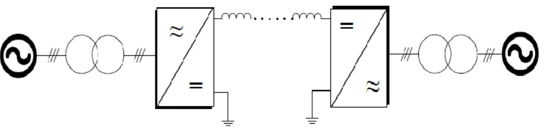
I.6.1 Back-to-back:
Back-to-back systems are composed of two converter stations. The conversion takes place in the main location, and these systems are not suitable for long-distance transmission. The block diagram depicted in Figure I-9 shows AC/DC conversion. This facilitates the connection between asynchronous grids. This kind of connection is also known as a unipolar system.
05
1.6.2 Monopolar Link :
A monopolar link (Figure 1-10) has one conductor and uses either ground and/or sea return. A metallic return can also be used where concerns for harmonic interference and/or corrosion exist. In applications with dc cables (i.e. HVDC Light), a cable return is used. Since the corona effects in a dc line are substantially less with negative polarity of the conductor as compared to the positive polarity, a monopolar link is normally operated with negative polarity.
Fig I-10 Monopolar link
1.6.3 Bipolar Link:
A bipolar link (Figure 1-11) has two conductors, one positive and the other negative. Each terminal has two sets of converters of equal rating, in series on the dc side. The junction between the two sets of converters is grounded at one or both ends by the use of a short electrode line. Since both poles operate with equal currents under normal operation, there is zero ground current flowing under these conditions. Monopolar operation can also be used in the first stages of the development of a bipolar link. Alternatively, under faulty converter conditions, one dc line may be temporarily used as a metallic return with the use of suitable switching.
06
1.6.4 Homopolar Link:
In this type of link (Figure 1-12) two conductors having the same polarity (usually negative) can be operated with ground or metallic return. Due to the undesirability of operating a dc link with ground return, bipolar links are mostly used. A homopolar link has the advantage of reduced insulation costs, but the disadvantages of earth return outweigh the advantages.
Fig I-12 Homopolar dc link
I.7 The components of an HVDC transmission system
To assist the designers of transmission systems, the components that comprise the HVDC system, and the options available in these components, are presented and discussed. The three main elements of an HVDC system are: the converter station at the transmission and receiving ends, the transmission medium, and the electrodes.
07
Figure I-13 The components of an HVDC transmission system
I.7.1 The converter station:
The converter stations at each end are replica’s of each other and therefore consists of all the needed equipment for going from AC to DC or vice versa. The main component of a converter station are:
I.7.1.1Thyristor valves:
The thyristor valves can be build-up in different ways depending on the application and manufacturer. However, the most common way of arranging the thyristor valves is in a twelve-pulse group with three quadruple valves. Each single thyristor valve consists of a certain amount of series connected thyristors with their auxiliary circuits. All communication between the control equipment at earth potential and each thyristor at high potential, is done with fibre optics.
I.7.1.2 VSC valves:
The VSC converter consists of two level or multilevel converter, phase-reactors and AC filters. Each single valve in the converter bridge is built up with a certain number of series connected IGBTs together with their auxiliary electronics.
08
VSC valves, control equipment and cooling equipment would be in enclosures (such as standard shipping containers) which make transport and installation very easy. All modern HVDC valves are water-cooled and air insulated.
I.7.1.3Transformers:
The converter transformers adapt the AC voltage level to the DC voltage level and they contribute to the commutation reactance. Usually they are of the single phase three winding type, but depending on the transportation requirements and the rated power, they can be arranged in other ways
I.7.1.4AC Filters and Capacitor Banks:
On the AC side of a 12-pulse HVDC converter, current harmonics of the order of 11, 13, 23, 25 and higher are generated. Filters are installed in order to limit the amount of harmonics to the level required by the network.. In the conversion process the converter consumes reactive power which is compensated in part by the filter banks and the rest by capacitor banks.
In the case of the CCC the reactive power is compensated by the series capacitors installed in series between the converter valves and the converter transformer. The elimination of switched reactive power compensation equipment simplify the AC switchyard and minimize the number of circuit-breakers needed, which will reduce the area required for an HVDC station built with CCC.
With VSC converters there is no need to compensate any reactive power consumed by the converter itself and the current harmonics on the AC side are related directly to the PWM frequency. Therefore the amount of filters in this type of converters is reduced dramatically compared with natural commutated converters.
I.7.1.5 DC filters:
HVDC converters create harmonics in all operational modes. Such harmonics can create disturbances in telecommunication systems. Therefore, specially designed DC filters are used in order to reduce the disturbances. Usually no filters are needed for pure cable transmissions as well as for the Back-to-Back HVDC
11
stations. However, it is necessary to install DC filters if an OH line is used in part or all the transmission system.
The filters needed to take care of the harmonics generated on the DC end, are usually considerably smaller and less expensive than the filters on the AC side. The modern DC filters are the Active DC filters. In these filters the passive part is reduced to a minimum and modern power electronics is used to measure, invert and re-inject the harmonics, thus rendering the filtering very effective.
I.8 Semiconductor devices for HVDC systems
Despite the huge cost of devices employed for the medium and high power applications, this kind of application covers only a much reduced part of the semiconductor total market [9].
An investigation on the most used semiconductor devices was provided for the HVDC connection's field. For each device the operating range was given in terms of managed power, moreover advantages and drawbacks which decided the replacement of one respect to one another were highlighted.
I.8.1 Diode
For HVDC connections the fast diodes for the free-wheeling and the clamping ones are used according to the topology. The operating voltage range for the single device is about 1-10 kV. Moreover these devices can reach currents of 2-7 kA. The device is almost composed by a monolithic junction even for Press-Pack structures.
I.8.2 Thyristor
These devices that can sustain voltages in the range of 10kV are matched for HVDC applications. On the market it can be found devices which can conduct current levels up to 5kA. Nevertheless, the thyristor is not a fully controllable switch.
Thyristors can reach very high voltage levels, they are very fast during turn-on and they dturn-on’t show overvoltage problems in series cturn-onnectiturn-on [11]-[10].
10
I.8.3
IGBT
The Insulate Gate Bipolar Transistor was introduced in 1981 combining a MOS gate with a bipolar transistor for high voltage sustaining and simple gate driving. Actually on the market there are devices which can sustain a voltage up to 6.5 kV and switch a current up to 750 A.
I.8.4 IGCT
The Integrated Gate-Commutated Thyristor is exclusively used for very high power applications such as medium voltage drives or wind turbine converters in the multi megawatt range. These devices can turn-off up to 6 kA under 4.5 kV. In the future, this device could be the best candidate for HVDC systems based on VSCs.
According to the claims made up to this point, VSC-HVDC systems can be chosen rather than CSC-HVDC ones because of a series of factors, such as:
Failures of the commutations due to AC network disturbances that could be avoided.
Independent managing of the active and reactive power.
The use of modulations such as PWM, which guarantees frequency very low harmonic distortion on the currents. The AC filter size can be greatly reduced.
That is why in the following section, multilevel VSC topologies, able to operate in high voltage applications, are considered.
I.9 VSC-HVDC multilevel topologies
Due to the limited current capability of the cables and semiconductor devices, HVDC systems require converters able to operate on around a hundred volts. In Figure I-14, the main topologies of voltage source inverters are reminded.
11
Figure I-14 Basic schema of vsc topologies for a simple one a).2-VSI b).and q multilevel topology c)
The simplest VSC topology is the two-level, three-phase bridge [12]. If this solution is adopted, many series-connected IGBTs are used to compose one device as shown in Figure I-15. As treated previously there is just one manufacturer available on the market for this solution.
Figure I-15 VSC2-level topology for high voltage employment
The connection of series devices leads to output voltage waveforms, which show high dv/dt, which is a main constraint for transmission line transformers. Moreover, for high power converters, the switching frequency is very low due to power losses and the limitations of the semiconductor device. To keep the harmonic impact under the limit imposed by the standards, an AC filter is necessary.
The use of multilevel converters enables work at a high-voltage level, with a high waveform quality. The main feature of these converters is that they draw a quasi-sinusoidal voltage waveform from several levels obtained from flying capacitors (like flying cap converters) [13] connected to each commutation cell.
In multilevel structures, due to the interleaved modulation technique, it is possible to achieve a series of advantages [13] - [14], such as:
12
Quasi-sinusoidal AC voltage waveform Low harmonic impact
Reduced costs for the filtering elements Possible direct connection to the MV grid
Reduction of semiconductor losses due to a very low single-switching frequency per device
An overview is given in the next section on the multilevel topologies candidate to be employed for high-power transmission.
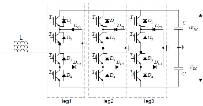
I.9.1 Neutral Point Clamped (NPC)
One of the topologies which literature started to consider is the NPC [14]. In Figure I-16, a three-level version is shown, but it is possible to add the components and place them correctly to increase the number of levels.
Figure I-16 Three-level three NPC topology
The component which characterizes this topology is the diode necessary to clamp the switching voltage to the half level of the DC bus, which is split into three levels by two series of connected bulk capacitors. In this topology, the middle point is also called the neutral point, outlined in Figure I-16 as the ground. By increasing the number of levels, the voltage which the diodes have to sustain rises. If the voltage rating of each diode is kept, more devices are necessary for the whole voltage. For this reason, if the number of voltage levels that the system can impose is N, (N-1)2 diodes are necessary. For high-DC voltages, the system becomes less convenient due to the huge number of diodes.
13
I.9.2 Flying capacitor
Another multilevel topology which is suitable for high-power applications is the Flying Capacitor structure with N imbricated cells (Figure I-17). The output inductor value is calculated to limit the output current ripple at the equivalent switching frequency. [15] The FC topology includes N-1 flying capacitors, and the operating voltage of each cell is Vd/N [15]. One drawback of this topology is the stored energy in the flying capacitors close to the DC bus (voltage and energy increase with index i). However, it is possible to connect capacitors in the series to sustain high voltage, but it is not certain that the voltage will be equally shared between them.
Figure I-17 Three-phase flying capacitor converter
The two topologies analyzed present a better reduction in the harmonics. Despite the improvements which they are able to reach, these kinds of multilevel converters present a series of limitations/drawbacks. For this reason, they did not succeed in these HV application demands [16].
Not suitable for the industrial series production (thanks to the modular construction in order to enable scaling to different power and voltage levels, using the same hardware [17])
Unwanted EMI disturbances generated by a very high slope (di/dt) of the arm currents
14
The DC bulk capacitor stores a huge quantity of energy which leads to damages under faulty conditions
The stored energy of the concentrated DC capacitor at the DC-Bus results in extremely high surge currents and subsequent damage if short circuits at the DC-Bus cannot be excluded
Harmonics on the AC current must always be suppressed
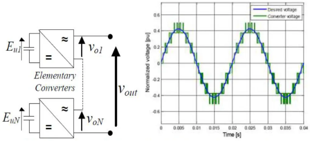
I.9.3 Cascaded Multilevel Inverters
These structures are characterized by a series connection of elementary converters that are normally identical, as shown in Figure I-18. Each cell corresponds to a voltage level. According to the particular modulation technique, it is possible to achieve the desired voltage waveform according to the imposed reference (Figure I-19).
Figure I-19 Cascaded multilevel stage Figure I-18 Example of multilevel wave from
With respect to the traditional topologies, cascaded structures ensure the modularity of the system by ensuring series industrial production. Due to the modularity, they do not present upper-DC voltage limits. In fact, it is possible to add more series cells to sustain the desired voltage.
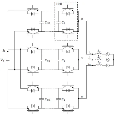
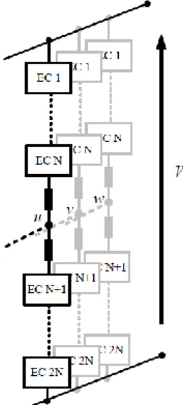
A topology which has been affirmed in the last decade is the Modular Multilevel Converter. This structure is more and more often chosen for VSC-HVDC power stations [18].
The converter is a composition of series-connected elementary cells (Figure I-20). This converter offers the possibility to regulate the active and reactive power
15
independently. Each phase is composed by two groups of elementary cells (1..N and N+1…2N), called branches. Each branch conducts the half-phase current. As affirmed in [16], “At first glance, when being compared to conventional VSC or multilevel VSC, the new topology offers several features which may seem strange or definitely wrong”. Thanks to a series of advantages listed above, the next chapter pays attention to the main topology and sizing aspects for this structure:
Each arm conducts half current and in continuous conduction mode Arm inductances contribute to limit faulty conditions
The bulk capacitor is not necessary because there are two terminal cells Each capacitor cell voltage can be controlled very slowly with respect to the
current regulator
The DC link voltage can be controlled by the converter
Figure I-20 Modular Multilevel Converter base schema
I.10 Conclusions
The purpose of this chapter was to introduce the reader to the various aspects concerning HVDC transmission systems in general and VSC-based HVDC transmission systems in particular.
Thereby, the first part of this section was dedicated to the introduction to the HVDC transmission systems. In order to show why the HVDC transmission technology is more and more used in different applications, a comparison between HVAC transmissions and HVDC transmissions was presented and the advantages of the first technology were highlighted.
16
These advantages make the HVDC transmission systems suitable for several applications, such as: long distance bulk power transmissions, asynchronous connection of AC power systems etc.
The second topic discussed in this chapter was about basic HVDC system configurations. The four main configurations: monopolar, bipolar, back-to-back and multi-terminal were briefly explained.
The VSC-based HVDC transmission system technology was the next topic discussed. Advantages of this topology over the classic HVDC transmission topology were presented .
The chapter ends The basic configuration of a typical VSC-based HVDC system was presented and a short description of each components was given.
82
Chapter II
HVDC Modeling and
Control
Design
II.1 -Introduction :
In this chapter the mathematical modeling of the main components (VSC, filter and grid)of the VSC-based HVDC system will be described. The modeling of the components will be realized in the dq synchronous reference frame since the control will be implemented in the same reference frame.
then, we presents the design of the control strategies for the VSC-based HVDC transmission system. Firstly a brief presentation of the control strategies suitable for such an application will be realized. The chapter will continue with the individual presentation of all the control loops which will be used for simulating the VSC-HVDC system. The tuning process of these controllers will be also described. The PLL method to synchronize the system with the grid is going to be also introduced in this chapter.
II-2. System Modeling
II-2.1 Voltage Source Converter Model
82
Figure II.1 : Circuit diagram of a three-phase VSC
The three-phase mathematical model for a VSC similar to the one presented above was presented in [19] and [20]. If a balanced three-phase system with neutral connection is assumed and neglecting the resistance r of the switches [20], the voltage source converter can be modeled by using equations (II.1) - (II.3):
∑ ( ∑ ) ∑ ∑ where,
k - represents the index for the three-phase; dk - represents the duty cycle;
ek - represents the phase voltage; ik - represents the phase current; vDC - represents the DC-link voltage; iDC - represents the DC current;
r - represents the resistance of the switch;
L - represents the inductance of the phase reactor; R - represents the resistance of the phase reactor.
03
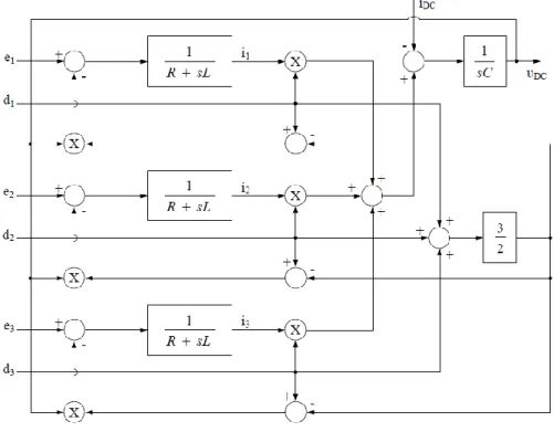
Thus, using equations (II.1) and (II.2), the block diagram of a three-phase VSC can be obtained:
Figure II.2 : The block diagram of a three-phase VSC
Based on the three-phase mathematical model of the voltage source converter, the converter's model in the dq synchronous reference frame can be derived. The model of the VSC in the dq reference frame will be implemented in Simulink and used for further study-cases analysis. In order to achieve the mathematical model of the VSC in the dq synchronous reference frame, the orientation of the dq system, in the complex plane, in respect to the three-phase system, is considered as presented in Figure II.3.
03
Thus, starting from the three-phase mathematical model of the VSC given by equations(II.1) - (II.3) and taking into account of the system's orientation (see Figure II.3) and of the Clarke and Park transformations, the dq mathematical model of the VSC was derived:
By separating equations (II.4) and (II.5) into d and q components the desired model of the converter was obtained and is given by:
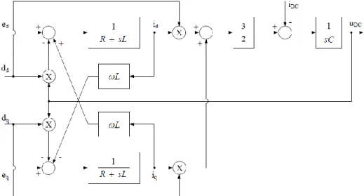
Using equations (II.6) - (II.8) the block diagram for the VSC, in the synchronous reference frame, can be obtained and it is shown in Figure II.4.
Figure II.4: The model of a three-phase VSC in dq synchronous reference frame
II-2.2 Filter Model
The electrical circuit of a three-phase C filter which is to be modeled in this section is shown in Figure II.5.
08
Figure II.5: Circuit diagram of a C filter
The three-phase mathematical model for a C filter similar to the one presented above is discussed in detail in [21]. If the resistance rf of the capacitor is neglected, the filter can be modeled by using equations (II.9), (II.10):
Where ,
k - represents the index for the three-phase; ek - represents the phase voltage;
ik - represents the current across filter capacitance; iPCCk - represents the phase current at PCC; ick - represents the current owing in the capacitor; Cf - represents the filter's capacitor;
rf - represents the internal resistance of the capacitor.
Based on the three-phase mathematical model of the filter, the filter's model in the dq synchronous reference frame can be derived. Thus, starting from the three-phase mathematical model of the filter given by (II.9) and (II.10) and taking into account the system's orientation (see Figure II.3), Clarke and Park transformation, respectively, the dq model of the filter was derived:
00
By separating equations (II.11) and (II.12) into the d and q components, the desired model of the filter was obtained and is given by:
Using equations (II.13) - (II.16) the block diagram for the C filter, developed in the synchronous reference frame, can be obtained and it is illustrated in Figure II.6.
Figure II.6: The model of the three-phase C filter in dq synchronous reference frame
II-2.3 Grid Model
Usually, a grid model can be developed by using the Thevenin equivalent circuit [22]. The equivalent circuit per phase for the grid model is presented in Figure II.7, where by an (R-L) equivalent impedance the distribution lines are emulated.
03
For each of the three phases, the voltage equation can be written as follows:
Where ,
- - represents the grid voltage ;
- - represents the voltage at the PCC .
However, for simplicity, the grid can be represented as an ideal symmetrical three-phase voltage source [23], as shown in Figure II.8.
Figure II.8: Symmetrical three-phase system The three-phase voltages of the symmetrical system are defined as:
Where,
- V represents the amplitude of the phase voltage; - represents the angular frequency
Furthermore , the line-to-line voltages are defined as:
Also, the three phase currents of the symmetrical system can be defined as:
03
` where,
- I represents the amplitude of the phase currents ;
- represents the phase shift angle between the voltage and current .
II-3 System Control
In the case of VSC-based HVDC transmission systems the transfer of power is controlled in the same way as in the case of a classical HVDC transmission. The inverter side controls the active power, while the rectifier side controls the DC voltage [24].
If the power transmission is considered between two AC grids, the power flow can be bidirectional. But, if the VSC-based HVDC system is used to deliver power from an offshore wind power plant (WPP), the active power flow is unidirectional (the offshore side is delivering active power to the onshore side and not vice-versa).
As presented in Chapter 1, one of the advantages of VSC-HVDC using PWM technologies that it makes possible to independently control the active power and the reactive power[25]. Thus, the reactive power may be controlled separately in each converter. The active power flow can be controlled by means of the DC voltage on the DC side or by variation of frequency on the AC side [24]. Moreover, the active power flow can be set manually.
In conclusion, when using VSC-based HVDC technology the active and reactive power, as well as the AC and DC voltage and the frequency can be controlled, fact which is presented in Figure II.9.
03
In the case of a VSC-based HVDC transmission between an offshore WPP and an Ac network, the offshore VSC controller maintains the offshore AC voltage and frequency, while the onshore VSC controller regulates the DC voltage and the reactive power (or AC terminal voltage) [27].
The control system of the VSC-based HVDC is realized by using a fast inner current control loop and several outer control loops, depending on the application [24], [28].
The control system of the VSC-HVDC systems has at its base level a fast inner current control loop controlling the AC currents. The AC current references are provided by the outer controllers [30]. The slower outer controllers include the DC voltage controller, the AC voltage controller, the active power controller, the reactive power controller and the frequency controller. Thus, the reference of the active current can be obtained from the DC voltage controller, from the active power controller or from the frequency controller. On the other hand, the reference of the reactive current can be derived from the reactive power controller or from the AC voltage controller [24].
According to [27], in the case when the VSC-HVDC technology is used for transmitting power from an offshore terminal to an onshore terminal the reference values for the current controllers are obtained as follows: on the offshore side, the AC voltage controllers are providing reference values for both active and reactive current while on the onshore side, the DC voltage controller provides the reference value for the active current and the reactive power controller or the AC voltage controller for the reactive current.
As it obviously is, not all the controllers can be used at the same time [24] and [28]. The choice of the different kinds of outer controllers is made depending on the application.
The overall control structure of the VSC-based HVDC transmission system considered in this project is shown in Figure II.10.
The inner current controller as well as all the outer controllers will be described in detail on the following.
03
Figure II.10: Overall control structure of the VSC-HVDC transmission system
II-3.1 Phase Locked Loop
The grid synchronization is a very important and necessary feature of grid side converter control. The synchronization algorithm is able to detect the phase angle of grid voltage in order to synchronize the delivered power. Moreover, the phase angle plays an important role in control, being used in different transformation modules, as Park's transformation.
There are several methods capable to detect the phase angle: the zero crossing detection, the filtering of grid voltages and the phase locked loop (PLL) technique [31].
In this project, the last mentioned algorithm is implemented in order to synchronize the delivered power.
PLL is a phase tracking algorithm, which is able to provide an output synchronized with its reference input in both frequency and phase [31]. The purposed of this method is to synchronize the inverter output current with the grid voltage, in order to obtain a unitary power factor.
The block diagram of the PLL algorithm implemented in the synchronous reference frame is presented in Figure II.11.
02
Figure II.11: Block diagram of PLL
The inputs of the PLL model are the three phase voltages measured on the grid side and the output is the tracked phase angle. The PLL model is implemented in dq synchronous reference frame, which means that a Park transformation is needed. The phase locking of this system is realized by controlling the q-axis voltage to zero. Normally, a PI controller is used for this purpose. By integrating the sum between the PI output and the reference frequency the phase angle is obtained.
The transfer function of the dq PLL system is given by [31]:
As it can be observed, this equation is similar to the second order transfer function having a zero that is shown in the following expression:
By comparing (II.27) and (II.28), the gain of the controller can be obtained. In order to calculate the parameters of the controller, a settling time Tset of 0:04 s and a damping factor = √ are chosen.
The PI parameters can be calculated as:
Where the natural frequency, is given by:
02
The grid phase angle obtained with the described PLL algorithm is shown in Figure II.12.
Figure II.12: Phase angle of grid voltage
II-3.2 Current Control Loop
The inner current controller is implemented in the dq synchronous reference frame [28],[32], [33]. Usually, the dq-control structures are associated with PI controllers due to their good behavior when regulating DC variables [33]. However, according to [30], the PI current controllers have no satisfactory tracking performances when they have to regulate coupled systems like the one described by equations (II.7) and (II.8). Therefore, in order to improve the performances of the PI current controllers in such systems, cross-coupling terms and voltage feed forward is usually used [32], [33], [34].
The structure of the inner current controller implemented in the synchronous reference frame is presented in Figure II.13.