HAL Id: tel-01710768
https://tel.archives-ouvertes.fr/tel-01710768
Submitted on 16 Feb 2018HAL is a multi-disciplinary open access archive for the deposit and dissemination of sci-entific research documents, whether they are pub-lished or not. The documents may come from teaching and research institutions in France or abroad, or from public or private research centers.
L’archive ouverte pluridisciplinaire HAL, est destinée au dépôt et à la diffusion de documents scientifiques de niveau recherche, publiés ou non, émanant des établissements d’enseignement et de recherche français ou étrangers, des laboratoires publics ou privés.
Experimental and Numerical Study of Micro-Fluidic
Oscillators for Flow Separation Control
Shiqi Wang
To cite this version:
Shiqi Wang. Experimental and Numerical Study of Micro-Fluidic Oscillators for Flow Separation Control. Mechanics of the fluids [physics.class-ph]. INSA de Toulouse, 2017. English. �NNT : 2017ISAT0017�. �tel-01710768�
THÈSE
En vue de l'obtention duDOCTORAT DE L’UNIVERSITÉ DE TOULOUSE
Délivré par:
Institut National des Sciences Appliquées de Toulouse (INSA de Toulouse)
Discipline ou spécialité:
Dynamiques des fluides
Présentée et soutenue par
WANG Shiqi
Le 1 Septembre 2017 Titre de la thèse:
Experimental and Numerical Study of Micro-Fluidic Oscillators for Flow Separation Control
JURY:
Laurent KEIRSBULCK, Professeur. Université de Valencienne. Rapporteur Sedat TARDU, Maître de Conférences. Institut Polytechnique de Grenoble. Rapporteur
Irina GRAUR MARTIN, Professeur. Université d’Aix-Marseille. Examinatrice Emmanuel GUILMINEAU, Chargé de Recherche. Ecole Centrale de Nantes. Examinateur
Nicolas MAZELLIER, Maître de Conférences. Université d’Orléans. Examinateur Stéphane COLIN, Professeur. INSA de Toulouse. Examinateur.
Lucien BALDAS, Maître de Conférences. INSA de Toulouse. Directeur de Thèse Azeddine KOURTA, Professeur. Université d’Orléans. Directeur de Thèse
Ecole doctorale :
Aéronautique, Astronautique (AA)
Unité de recherche :
Institut Clément Ader (ICA, CNRS UMR 5312)
Directeur(s) de Thèse :
(Directeur) Lucien BALDAS, Maître de conférences, INSA de Toulouse (Directeur) Azeddine KOURTA, Professeur, Université d’Orléans
Acknowledgement
The present research work has been carried out in Institut Clément Ader (ICA) of Institut National des Sciences Appliquées de Toulouse (INSA-Toulouse) with the collaboration of PRISME Laboratory of Orléans University during years 2013-2017 in the framework of GdR contrôle des décollements.
Foremost, I would like to express my sincere gratitude to my supervisors, Dr. Lucien Baldas and Prof. Azeddine Kourta who had proposed this project and offered me this precious chance persuing a degree abroad. Moreover, without their continuous interest, support and guidance during this study, I can’t accomplish it so smoothly.
Next, I would like to express my sincere thanks to Prof. Stéphane Colin and Dr. Nicolas Mazellier, who had contributed a lot of works, shared many helpful discussions and meaningful ideas during this study.
Also, I would like to thank Dr. Stéphane Orieux, Mr. Nicolas Laurien and Mr. Stéphane Loyer for their kindly help in preparing and doing the experimental tests during this study.
I am also most grateful to the reviewers of my thesis, Prof. Laurent Keirsbulck and Dr. Sedat Tardu, and other members in my defense committee, Prof. Irina Graur Martin and Dr. Emmanuel Guilmineau for their valuable feedbacks.
It is pleasure to thank my colleagues and also my friends in my team, Jie Chen, Hacene, Ernane, Yanfeng, Macros, Christine, Pascale, Ahmad, Varun, Guillermo, Daniel, Dominique, etc. for their valuable help and support both in my work and life. Many thanks also to the friends I have met in the lab and life, to name Tao Li, Jian Fu, Yiwei, Xiaohu, C. Chen, Donghai, Lunde, R. Xue, etc. who had made my life in Toulouse so colorful.
I appreciate a lot the scholarship offered by China Scholarship Council (CSC).
I owe special thanks to my wife, Nan Zhao, for supporting me during the hardships of such a long journey, for being patience and, for believing in me.
And last, but not least, I thank my parents, An’yu Wang and Qiuxiang Bai, and my sister, Xiaoxing Wang, who continuously encouraged me over the past years to go and find my way, even when it took me so far away from home. I feel very indebted to my family for their continuous encouragement and support to my study in abroad.
Abstract
Fluidic oscillators which can generate periodic excitations are very promising for active flow control applications, due to their reliability and robustness, as their internal flow oscillation is totally self-induced and self-sustained. The main objective of this work is to identify the underlying mechanisms controlling the dynamics of this kind of fluidic oscillator and to propose guiding lines for the design of oscillators. Experimental analysis of several oscillator prototypes and associated numerical simulations have permitted to explain that the jet switching in this kind of oscillator is controlled by pressure gradients in two critical parts of the device. From these analyses, a simple function has been proposed to estimate the oscillation frequency. Two synchronization methods, allowing the control of the phase lag between the actuators, have been proposed and validated experimentally and by numerical simulations. An array of micro-fluidic oscillators has then been designed and tested on a ramp separated flow, showing much higher efficiency compared to other kind of fluidic actuators tested on similar wall flows in previous studies.
KEY WORDS :
Fluidic Oscillator, Coanda effect, Active flow control, Ramp flow, PIV, OpenFoam, Hot-wire anemometry
Résumé
Les oscillateurs fluidiques qui peuvent générer des excitations périodiques sont des actionneurs très prometteurs pour des applications de contrôle actif des écoulements. Les oscillations sont en effet complètement auto-induites et produites en l'absence de parties mobiles ce qui rend ces actionneurs très intéressants en termes de fiabilité et de robustesse. Ce travail de thèse avait pour objectif principal d'identifier les mécanismes physiques qui contrôlent la dynamique de fonctionnement de ce type d'oscillateurs fluidiques et de proposer des lignes directrices pour la conception d'oscillateurs dont les performances soient adaptées aux applications de contrôle d'écoulements envisagées. L'analyse expérimentale de plusieurs prototypes couplée à des simulations numériques a permis de mettre en évidence que le mécanisme de basculement du jet dans ce type d'oscillateurs est contrôlé par les gradients de pression existants au niveau de deux parties critiques de ces actionneurs. A partir de cette analyse, une relation simple a été établie permettant d'estimer la fréquence des oscillations. Deux méthodes de synchronisation, permettant le contrôle du déphasage entre les actionneurs, ont été proposées et validées expérimentalement ainsi qu'à l'aide de simulations numériques. Une matrice de micro-oscillateurs fluidiques a été conçue, fabriquée et finalement intégrée sur une rampe installée en soufflerie. L'analyse expérimentale de son efficacité pour le contrôle de l'écoulement séparé a mis en évidence un gain important par rapport aux résultats obtenus lors de travaux précédents sur des écoulements de paroi similaires à l'aide d'autres types d'actionneurs fluidiques.
MOTS CLES:
Oscillateur fluidique, Effet Coanda, Contrôle actif d'écoulement, PIV, Ecoulement sur une rampe, OpenFoam, Anémométrie Fil Chaud
Résumé long en français
Au cours des dernières décennies, de nombreux travaux ont concerné l'étude des actionneurs pour le contrôle actif d’écoulement, avec différents objectifs tels que la réduction de la traînée sur les corps non profilés 1, l'augmentation de la portance des surfaces portantes 2,3 ou encore l'amélioration du mélange dans les chambres de combustion 4,5, etc. De nombreux travaux de recherche (par ex. Greenblatt and Wygnansky 6) ont montré que, comparativement aux méthodes de contrôle passives traditionnelles ou aux méthodes d'aspiration ou de soufflage continu, le contrôle actif d’écoulement basé sur des excitations fluidiques périodiques est beaucoup plus efficace, avec un gain de deux ordres de grandeur en termes de quantité de mouvement ajoutée. Ces perturbations périodiques peuvent être fournies par différents types d'actionneurs tels que les actionneurs ZNMF (Zero Net Mass Flow), les actionneurs plasma et les MEMS (Micro-Electro-Mechanical-Systems)7. Parmi eux, les oscillateurs fluidiques peuvent émettre des jets oscillants dans une grande plage de fréquence et de vitesse de fonctionnement lorsqu'ils sont alimentés en fluide sous pression, sans nécessiter de partie mobile car leurs oscillations sont totalement auto induites et auto-entretenues et ne dépendent que de la dynamique interne de l’écoulement, ce qui constitue un excellent avantage en termes de fiabilité et de robustesse 8-10.
Le comportement d'un oscillateur fluidique à double boucle de rétroaction produisant deux jets pulsés est tout à fait différent de celui d'autres types d'oscillateurs basés sur l'effet Coanda, comme l'oscillateur fluidique sonique 37 ou l'oscillateur fluidique à jet balayant 43 et ne peut pas être clairement expliqué par les théories existantes. Ce travail de thèse s'est ainsi focalisé sur la clarification des mécanismes sous-jacents qui contrôlent la dynamique de ce type d'oscillateur fluidique dans le but de proposer des outils d'aide à la conception d'oscillateurs offrant les performances (fréquence et vitesse du jet pulsé) attendues pour les applications de contrôle auxquelles ils sont destinés. A partir de cette analyse, une matrice d'oscillateurs a aussi été développée et testée pour contrôler un écoulement séparé sur une rampe.
Après une brève introduction sur les différentes stratégies de contrôle des écoulements et sur les actionneurs fluidiques typiques, l'étude bibliographique a porté sur les différents types d'oscillateurs fluidiques, soulignant l'intérêt d'utiliser des oscillateurs fluidiques à double boucle de rétroaction générant deux jets pulsés pour les applications de contrôle d'écoulements et mettant en évidence le manque de connaissances sur les mécanismes physiques régissant leur comportement. Le cœur de ce travail de thèse a ensuite été présenté en quatre parties principales,
concernant respectivement l'analyse expérimentale des performances de 4 prototypes d'oscillateurs, la simulation numérique des écoulements instationnaires dans ces oscillateurs pour identifier les principaux mécanismes physiques contrôlant leur dynamique de fonctionnement, le développement de procédés de synchronisation d'un ensemble d'oscillateurs et l'application de ce réseau d'actionneurs fluidiques à la commande de l'écoulement séparé sur une rampe.
Quatre nouveaux prototypes d'oscillateurs ont été conçus et caractérisés expérimentalement à la fois par anémométrie fil chaud et à l'aide de capteurs de pression à large bande passante. Ces mesures ont confirmé que la vitesse moyenne des jets pulsés générés est contrôlée par l'aire de la section du col de la buse d'alimentation et la pression totale d'entrée. Cependant, l'amplitude de la vitesse de sortie et son évolution avec le temps peuvent également être affectées par la section du col de la buse ainsi que par d'autres facteurs géométriques internes tels que la symétrie interne du dispositif. En outre, la longueur et le diamètre de la boucle de rétroaction jouent un rôle important sur les performances de l'oscillateur, en particulier sa réponse en fréquence. Une relation, déduite des mesures expérimentales, a été proposée pour estimer la fréquence d'oscillation en fonction de la longueur de ces boucles de rétroaction.
Les modèles numériques développés sous OpenFOAM ont permis une estimation assez précise de la fréquence de fonctionnement. Une analyse détaillée des résultats des simulations a montré que, dans ce type d'oscillateur fluidique, la déviation du jet principal est provoquée non seulement par la différence de pression entre les ports de contrôle de l'oscillateur, mais aussi par la différence de pression entre ses branches. Dans les configurations étudiées, la valeur seuil de la différence de pression entre les ports de contrôle permettant de provoquer par elle-même la déviation du jet est beaucoup plus élevée que la différence de pression nécessaire entre les branches. Cependant, lors de la combinaison de ces deux effets, le basculement du jet devient beaucoup plus facile.
On a montré que le mécanisme de commutation était lié à la propagation aller-retour des ondes de pression dans les branches de l'oscillateur et ses boucles de rétroaction: juste après la commutation du jet, une onde de compression à haute pression se propage dans la branche dans laquelle le jet est attaché et dans la boucle de rétroaction correspondante tandis qu'une onde de détente basse pression se propage dans l'autre branche et l'autre boucle de retour. Lorsque ces ondes arrivent au niveau des ports de contrôle, elles se réfléchissent et le jet est déstabilisé par l'inversion de la différence de pression à sa base. La commutation se produit lorsque les ondes de pression réfléchies ont atteint la base des branches provoquant l'inversion
de la différence de pression entre les branches. Les ondes de pression se propageant approximativement à la vitesse du son Co, la période d'oscillation T peut être liée à la longueur de boucle de retour Lf par la relation nouvellement proposée T = 4Lf / Co , ce qui confirme la relation empirique déduite des résultats expérimentaux. Une relation plus précise a également été proposée pour calculer la fréquence d'oscillation, en tenant compte de la vitesse de l'écoulement dans les branches et les boucles de rétroaction de l'oscillateur. Ces simulations numériques ont également permis d'expliquer la non-dépendance de la fréquence d'oscillation à la pression d'alimentation.
Deux nouvelles méthodes, basées sur des interconnexions entre les boucles de rétroaction, ont été proposées pour synchroniser deux oscillateurs similaires. Ces deux méthodes ont été validées expérimentalement et numériquement. La première conduit à une fréquence proche de celle des oscillateurs fonctionnant séparément et les jets pulsés générés par ces deux dispositifs sont quasiment en opposition de phase. La deuxième méthode conduit à une fréquence beaucoup plus faible et une différence de phase entre les actionneurs proche d'un quart de période. Les simulations numériques ont également permis d'expliquer le comportement dynamique des oscillateurs synchronisés et de prouver la faisabilité de la synchronisation d'un réseau de 4 oscillateurs fluidiques en utilisant la première méthode d'interconnexion.
Dans la dernière partie de ce travail, 12 oscillateurs fluidiques identiques ont été intégrés dans une rampe pour tester leur capacité à contrôler la séparation de l’écoulement. La synchronisation de ce réseau d'oscillateurs fluidiques en utilisant la première méthode d'interconnexion a été validée expérimentalement. Les champs d'écoulement moyen et fluctuant sur la rampe, avec et sans action de ce réseau d'oscillateurs fluidiques, ont été acquis par PIV dans une soufflerie. Les résultats obtenus montrent que ce réseau d'oscillateurs fluidiques est très prometteur, compte tenu du faible coefficient de quantité de mouvement Cμ nécessaire pour éliminer totalement la séparation, comparativement aux valeurs optimales trouvées dans la littérature. L'analyse du champ moyen turbulent a montré que les mécanismes de contrôle sous-jacents étaient liés à une augmentation de la turbulence dans la région de la rampe due aux jets pulsés générés par les oscillateurs, conduisant à une augmentation nette par rapport au cas sans actionnement, de la force transférée de l’écoulement principal vers la couche de cisaillement.
I
Contents
Contents ... I
Nomenclature ... V
Introduction ... 1
Chapter 1. Background of the Study and Literature Review ... 3
1.1 Phenomenon of boundary layer separation ... 3
1.2 Separation control methods ... 6
1.3 Introduction to fluidic oscillators ... 8
1.4 Coanda oscillators: the state of art ...11
1.4.1 Sonic fluidic oscillator ... 12
1.4.2 Sweeping jet Coanda fluidic oscillator ... 15
1.4.3 Pulsing jet relaxation fluidic oscillator ... 16
1.4.4 Other kinds of Coanda oscillator ... 20
1.5 Efficient separation control by periodic jets ... 21
1.6 Conclusions ... 24
Chapter 2. Design and Experimental Characterization of Fluidic Oscillator Prototypes ... 27
2.1 Design of new prototypes ... 27
2.2 Hot wire characterization of Osc.1 and Osc.2 ... 30
2.2.1 Description of the test bench ... 30
2.2.2 Frequency response ... 31
2.2.3 Sample velocity signals of Osc.1 ... 32
2.2.4 Sample velocity signals of Osc.2 ... 34
2.2.5 Sensitivity of the internal geometry ... 35
2.2.6 Remarks and comments ... 36
2.3 Frequency characterization of Osc.3 ... 36
2.3.1 Influence of FBL on the oscillation frequency ... 37
2.3.2 First observations of the influence of feedback loops diameter/width ... 40
2.4 Conclusions ... 41
Chapter 3. Numerical Tools and Validation ... 43
3.1 Introduction to OpenFOAM... 43
3.2 Numerical settings ... 45
3.3 Validation of the numerical models ... 46
3.3.1 Measurement of the oscillators' internal geometry by X-ray tomography ... 46
II
3.3.3 Velocity prediction capability ... 48
3.4 Conclusions ... 50
Chapter 4. Numerical Analysis of Oscillation Dynamics ... 51
4.1 Identification of the key factors controlling the oscillations ... 52
4.1.1 Qualitative analysis of the switching process inside the oscillator ... 52
4.1.2 Detailed study of the oscillation process inside the device ... 55
4.2 Numerical study of the effects of two pressure differences ... 59
4.2.1 Isolated effect of the pressure difference between the control ports ... 60
4.2.2 Isolated effect of the pressure difference between the two branches ... 61
4.2.3 Combined effects of both pressure differences ... 61
4.3 Numerical study of the influence of inlet pressure on the oscillation dynamics ... 63
4.3.1 First analysis on a simplified geometry ... 63
4.3.2 Detailed numerical analysis of the inlet pressure effects ... 64
4.4 Conclusions ... 67
Chapter 5. Synchronization Study of Fluidic Oscillators ... 69
5.1 Synchronization of two oscillators ... 69
5.1.1 Inter-connection patterns for the synchronization of two oscillators ... 69
5.1.2 Description of the test bench ... 70
5.1.3 Test results ... 71
5.2 Numerical analysis of the flow dynamics in synchronized configurations ... 73
5.2.1 Simulation of two separated oscillators ... 73
5.2.2 Simulation of two oscillators synchronized with 1st inter-connection pattern ... 74
5.2.3 Simulation of two synchronized oscillators with 4th inter-connection pattern ... 80
5.3 Synchronization of an array of fluidic oscillators ... 85
5.4 Conclusions ... 86
Chapter 6. Efficiency of the Oscillator Array in Controlling Separated Flow in a Ramp ... 87
6.1 Design and Characteristics of an array of fluidic oscillators ... 87
6.1.1 Design of the oscillator array ... 87
6.1.2 Preliminary tests on a single fluidic oscillator ... 88
6.1.3 Synchronization test of the array ... 92
6.2 Description of the ramp flow test bench ... 94
6.2.1 Wind tunnel and ramp ... 94
6.2.2 Measurement devices ... 96
6.3 Measured flow field ... 97
6.3.1 Mean field of baseline flow ... 98
III
6.4 Discussion about the control mechanisms ... 102
6.4.1 Momentum equations governing the mean flow: ... 103
6.4.2 Pressure gradient field of both baseline case and controlling case ... 103
6.4.3 Focus on analysis of pressure gradient in x direction: ... 105
6.4.4 Turbulent Kinetic Energy and turbulence production analysis ... 108
6.5 Conclusions ... 111
Chapter 7. Conclusions and Perspectives ... 113
References ... 117
Annex 1. Preliminary Study of a First Oscillator Prototype ... 123
Annex 2. Sensitivity Study of the Numerical Schemes in OpenFOAM ... 135
V
Nomenclature
Roman Symbols
Ao outlet slot area (m2)
At throat section area (m2)
c wave propagation velocity (m s)
ca bulk propagation velocity (m s)
C average pressure wave propagation velocity inside the oscillator (m s)
CCFL cell courant number
Cd drag coefficient
Cl lift coefficient
Co speed of sound in ambient environment (m s)
C injection momentum coefficient
D diameter of feedback tube (m)
D’ width of feedback channel (m)
F+ non-dimensional oscillation frequency
f oscillation frequency (Hz)
fm measured oscillation frequency (Hz)
fs-s oscillation frequency simulated from scanned geometry (Hz)
fs-d oscillation frequency simulated from designed geometry (Hz)
H depth of a fluidic oscillator (m)
h ramp step height (m)
K constant for air (m s-1 K-0.5)
l length or distance (m)
L characteristic length (m)
Lr recirculation region length (m)
Lt length of feedback loop connection tube (m)
Lf feedback loop length (m)
m mass flux (kg)
m mass flow rate (kg/s)
mb blowing mass flow rate (kg/s)
VI
P pressure (Pa)
Pcr critical pressure (Pa)
Patm atmosphere pressure (Pa)
Pi inlet total pressure (Pa)
ΔP pressure difference (Pa)
P production of turbulent kinetic energy (m2 s-3)
R aerodynamic force on an airfoil (N)
Rd drag force on an airfoil (N)
Rl lift force on an airfoil (N)
Rg specific gas constant (J kg−1 K−1)
Re Reynolds number
S surface area of an airfoil (m2)
Sr Strouhal number
Srm modified Strouhal number
t time (s)
td deflection time (s)
t
basic time unit (s)
T oscillation period (s) a
T temperature (K)
Tatm atmosphere temperature (K)
Ti* inlet total temperature (K)
T
time difference or time duration (s)
u local fluid velocity (m s)
u’ fluctuation of velocity in x direction (m s)
U velocity (m s)
U free stream velocity (m s) b
U blowing jet velocity (m s)
max
b
U maximum velocity of unsteady blowing jet (m s)
rms b
U root mean square value of the velocity of unsteady blowing jet (m s)
Ux velocity in x direction (m s)
Uy velocity in y direction (m s)
VII
v’ fluctuation component of velocity in y direction (m s) R
V velocity ratio
w throat section width of a fluidic oscillator (m)
Y+ dimensionless wall distance
Greek Symbols
τt transmission time (s)
τs switching time (s)
ξ empirical constant
γ heat capacity ratio
λ dimensionless velocity coefficient
δ boundary layer thickness (m)
μ dynamic viscosity (kg m−1 s−1)
ν kinematic viscosity (m2 s−1)
η incidence angle of an airfoil (o)
ω span width of a controlled flow (m)
ρ density (kgm-3)
χ expansion rate of shear layer thickness
ψ force loss or force gain approximation (m s-2)
Φ gradient of stagnation pressure in streamwise direction (Pa m-1)
Abbreviations
AFC Active Flow Control
BC Boundary Condition
CFL Courant-Friedrichs-Lewy FBL Feedback Loop Length
HPCW High Pressure Compression Wave LPEW Low Pressure Expansion Wave
MEMS Micro-Electro-Mechanical-Systems PIV Particle Image Velocimetry
RMS Root Mean Square
RANS Reynolds-averaged Navier–Stokes TKE Turbulent Kinetic Energy
Introduction
1
Introduction
The study of actuators for active flow control has been in rapid expansion in the last several decades, pursuing different goals such as reducing drag on bluff bodies1, increasing lift of airfoils2, 3 or enhancing mixing in combustion chambers4, 5, etc. Compared to traditional passive control methods or steady blowing methods, the active flow control based on periodic fluidic excitations is much more efficient, with a gain of two orders of magnitude in terms of added momentum, as demonstrated by numerous researches (e.g., Greenblatt and Wygnanski 6). These periodic fluidic disturbances can be provided by various kinds of actuators such as ZNMF (Zero Net Mass Flow) actuators, plasma actuators and MEMS (Micro-Electro-Mechanical-Systems)7. Among them, fluidic oscillators can emit oscillating jets in a large operating frequency and velocity range when supplied with a pressurized fluid without requiring any moving part, since their oscillations are totally self-induced and self-sustained and only depend on the internal flow dynamics, which is a great advantage in terms of reliability and robustness8-10.
Compared to the other kinds of oscillators based on the Coanda effect, like the sonic fluidic oscillator or sweeping jet fluidic oscillator, the behavior of a pulsing jet relaxation fluidic oscillator is quite different and cannot be clearly explained by the existing theories. The present thesis is thus focusing on making clear the underlying mechanisms controlling the dynamics of this kind of fluidic oscillator with the objective to propose guiding lines for the design of oscillators providing the performances (pulsed jet frequency and velocity) requested by flow control applications. It is also intended, from this analysis, to develop and test oscillator prototypes to control a ramp separated flow.
In the first chapter, a general description of the boundary layer separation phenomenon is given and various separation control methods are introduced. A detailed review about all kinds of fluidic oscillators, including their classifications, their operating dynamic, etc. is also presented. The typical separation control applications on ramp or hump flows are also briefly reviewed with a focus on the optimal configurations identified.
In the second chapter, four oscillator prototypes are designed and experimentally characterized. The outlet velocity temporal evolution patterns are presented. The influence of the feedback loop length and diameter on the oscillation frequency is examined.
Introduction
2
Numerical modeling of the oscillators based on an open source code is presented in the third chapter. The optimal numerical schemes are identified after a sensitivity study and validated by comparison with experimental data.
A detailed numerical study of the internal flow patterns of a fluidic oscillator is then conducted in chapter four. The influence of the inlet pressure on the fluidic oscillator’s performances is also analyzed.
Since the fluidic oscillator’s performances are very sensitive to internal and external parameters, some methods have to be developed to force an "in phase" running of a series of oscillators, which is very important for analyzing their control efficiency. Chapter five is thus fully devoted to introduce two synchronization methods that have been both experimentally and numerically validated and analyzed in detail.
An array of miniaturized fluidic oscillators, synchronized by one of the proposed methods, is then tested in a wind tunnel to control a separated flow on a ramp. The experimental characterization of the ramp flow without and with control is performed for various operating conditions thanks to hot wire and PIV measurements and the efficiency of the oscillator array is analyzed and presented in chapter six.
Finally, the main conclusions and the major perspectives of this work are summarized in chapter seven.
Cha
Lite
1.1
Let' due to t maximu leading where th boundar to the po The fully de the plate a consta Figure 1-Dep laminar whe is the dyapter 1
erature
Phenom
's consider a the viscosity um U∞ in th edge where he velocity ry layer”. T oint where t e value of δ eveloped flo e due to the ant maximu 1. Boundary l pending on r, transitiona ere ρ is the d ynamic visc B1. Ba
e Revi
menon of
a flat plate i y of the flu he free stre e the fluid st profile in th he thicknes the velocity will increas ow as shown shear stress um value in layer on a flat the Reyno al or turbule density of f cosity of the Background of tackgro
iew
f bounda
in a fluid, e. id, there wi eam. This p tarts to flow he flow is in s δ of this b y is 99% of se with the d n in Figure s at the surfa the fully de plate olds numbe ent. fluid, L is a e fluid. For athe Study and L
ound o
ary layer
.g., air, flow ill be a velo profile build w past the su nfluenced b boundary lay the “free str distance from 1-1 for a fl ace increase eveloped flo er defined b ρLU Re μ characterist a flat plate, Literature Revief the S
r separat
w with a rela ocity profile ds up gradu urface. This by the shear yer is define ream” veloc m the leadin at plate. Sim es from zero ow region. by Eq.(1-1) tic length, U L is the dis ewStudy
tion
ative "free st e from 0 on ually from t region next stress at the ed as the dis city. ng edge up t multaneousl o at the begin ), this boun U∞ is the fre stance fromand
stream" velo n the plate w the point ca t to the plate e wall is ca stance from to a maximu ly the drag nning of the ndary layer ee stream ve the leading 3 ocity U∞: wall to a alled the e surface lled “the the wall um in the force on e plate to r can be (1-1) elocity, μ g edge.4 The directio the case increase quickly adverse velocity Figure 1-Thi industri is locate aerodyn and a li pressure extrados Figure 1-e thickn1-ess n of flow w e of a conver es along the decrease an pressure g y reversal oc 2. Separation s phenomen al applicatio ed in a flow namic force ift force Rl e force on s. This lift f 3. Aerodynam B of the boun when the flu
rgent flow. e flow dire nd reverse in gradient. Th ccurs as sho of a boundary non called b ons, especia w with a free R it bears h in the perp the intrado force increa mic forces on a Background of t ndary layer uid accelerat Nevertheles ction. The n direction w he boundar own in Figu y layer11 boundary la ally the wing
e stream ve has two com pendicular d
s (or the lo ases with the
an airfoil secti
the Study and L
will becom tes, thus ma ss, the situa
velocity of when the flu ry layer wil ure 1-2. . ayer separat g stall of a p elocity U∞, mponents: a direction. T ower wall o e flow veloc ion12 Literature Revie me thinner i aintaining th ation will be f the fluid w uid moment ll be lifted
tion, can lea plane. Cons as shown in a drag force The aerodyn of the airfo city. ew f the pressu he fluid clo e totally diff within the b tum is too lo away from ad to seriou idering an a n the schem e Rd in the m namic lift f il) and a su ure decrease ose to the w ferent if the boundary la ow to overc m the surfac us accidents airfoil sectio matic Figure main flow d force results uction force es in the all, as in pressure ayer will come the ce if this in some on which 1-3, the direction s from a e on the
Two A li A d whe coeffici evolutio augmen phase w η may tr This bou the velo presenc drag. Th plane an Figure 1-┅┅┅Re o coefficien ift coefficien drag coeffici ere S is the ents are link on of Cl and ntation of η when the pla rigger a sud undary laye ocity is muc e of this hig his sudden f nd should b 4. Variation o e = 3.1×10⁴ B nts can be de nt ( Cl ): ient ( Cd ): upper or lo ked to the i d Cd with η
, the lift inc ane needs a s dden fall of t
er separation ch lower an gh pressure fall of the lif e totally avo of Cl and Cd Background of t efined assoc ower side s incidence an η is shown creases sign sufficient li the lift value n produces i nd thus the zone leads ft value is na oided. d C in function
the Study and L
ciated to the 2 1 2 l l R C ρSU 2 1 2 d d R C ρSU surface area ngle η of th in Figure 1 nificantly. T ft at a low v e due to the indeed a rec pressure is both to a de amed “stall” n of η in case o Literature Revie e lift and th 2 2 a of airfoil. he airfoil re -4. As it ca This propert velocity. Ho boundary la circulation b s much high ecrease of th ” which is o of a plane airfo ew e drag force The value elative to th an be easily ty is exploit owever, a lar ayer separat bubble on th her than in he lift and t of course ver foil.13 ──── es: of the lift a he flow. The y observed, table in the rge augmen tion on the e he extrados the main fl to an increa ry dangerou ── Re = 6.5× 5 (1-2) (1-3) and drag e typical with the e landing ntation of extrados. in which low. The ase of the us for the ×105,
6
1.2
In a drag wh it travel aerodyn propose passive Pas Pas aerodyn simplici configu vortex g Figure 1-Vor reduced generato series o downstr wall reg effectiv vortex g has been for lowSepara
aerodynami hich is cause s through th namic and h ed many sol and active ssive flow co sive contro namic drag, ity is also th uration chan generators a 5. a) sketch o rtex generat d scale, perpors are mou of vortices a ream of the gion, the bou
eness of wi generators o n demonstra aspect ratio B
ation con
cs, flow sep ed by the pr he fluid. For hydrodynam lutions to ac flow contro ontrol techn ol technique which are b he main dra nges 14. The and the wingf a working v
tors are wid pendicular t unted with along the su wing and i undary laye ings and co on a modifi ated that thi o 3D bluff-b Background of t
ntrol me
paration can ressure diffe r this reason mic surfaces chieve this g ol strategies niques es are the m based on the awback of su most repre g fences em ortex generato dely employ to the main an angle of urface of th induce mom er separation ntrol surfac ed Ahmed is kind of co bodies, likethe Study and L
ethods
n often resu erence betw n, much effo s which del goal. In gen . most conve e modificati uch devices esentative a mployed on a or;15 b) wing f yed on airp n wing. As f attack rela he wing. As mentum tran n and the ae ces can thus body has a ontrol meth road vehicl Literature Revie ult in increa ween front anort and resea lay the flow neral, these entional and ion of the sh s which are applications airfoils as il fences on the planes and c it can be s ative to the s the create nsfer betwee erodynamic s be largely lso been ex hod can lead
les.
ew
ased drag, p nd rear surfa arch has gon w separation solutions li d simplest w hape of the often irrele of passive llustrated in airfoil of Mig can be cons een in Figu airflow in d streamwi en the free-s stalling can improved. xploited by A d to a signifi particularly faces of the o ne into the d n. Research ie in two cat ways to red wall. Howe evant when control ma n Figure 1-5 g-17 sidered as w ure 1-5a, th order to ge ise vortices stream and n be delayed The applic Aider et al. icant drag r pressure object as design of ers have tegories: duce the ever, this the flow ay be the 5. wings, at he vortex enerate a develop the near d and the cation of .16 and it eduction
Background of the Study and Literature Review
7
Wing fences, also called boundary layer fences, are fixed aerodynamic devices attached to the aircraft wings. They are often used to obstruct span-wise airflow along the wing and prevent the entire wing from stalling at once. They are often seen on swept-wing aircrafts as shown in Figure 1-5b.
Active flow control techniques
On the contrary, active control methods permit to modify the boundary layer in relation with the flow configuration and need energy supply. Thus, these methods necessarily require actuators to interact with the flow. Many different types of actuators, such as thermal actuators, electromagnetic actuators, pneumatic actuators, synthetic jets, oscillators, etc.17, 18, have been developed for active flow control applications. A detailed summary and comparison of various actuators have been proposed by Cattafesta et al. 7 as shown in Table 1-1.
These actuators can be classified into three main categories: fluidic actuators, moving surface actuators and plasma actuators. In each category, some sub-categories can also be found. Among those, the fluidic oscillators are drawing more and more attention because they can operate in a large operating frequency and velocity range when supplied with a pressurized fluid, without requiring any moving part. Their oscillations are totally self-induced and self-sustained and only depend on the internal flow dynamics, which is a great advantage in terms of reliability and robustness.
Table 1-1. Summary of common unsteady flow control actuators proposed by Cattafesta et al. 7
Type Subtype Advantages Disadvantages
Fluidic
ZNMF Requires no external fluid source Peak velocities typically limited to low to moderate subsonic speeds
Amenable to various types of drivers and
sizes Resonant devices
Suitable for feedback control Unsteady
valves Capable of high velocities with either fast time response or high bandwidth but generally not both
May not be amenable to feedback control
Requires an external flow source Oscillators Capable of producing large disturbances Standard versions not suitable for
feedback control Amenable to a range of sizes and hence
frequencies Requires an external flow source
Potential extensions possible to enable independent control of frequency and velocity
Combustion Capable of producing large perturbations in high-speed flows
Currently limited to relatively low frequencies (a few hundred hertz)
Background of the Study and Literature Review
8
Moving surface
Piezoelectric flaps
Simple design amenable to different frequency ranges of interest
Has constant product of max deflection and bandwidth
Can produce spanwise or streamwise
vorticity Susceptible to fluid loading
Suitable for feedback control Resonant devices
Active
dimples Potentially suitable for feedback control of turbulent wall-bounded flows Further development needed to achieve required size and frequency response Plasma
SDBD Easily installed on models Limited velocity output
Low mass Requires high voltage (kV)
Fast time response No moving parts
Sparkjet All solid-state device capable of producing large perturbations in high-speed flows
Potential issues associated with EMI, acoustic level, and high temperature
Abbreviations: EMI, electromagnetic interference; SDBD, single dielectric barrier discharge; ZNMF, zero-net mass flux
1.3
Introduction to fluidic oscillators
Fluidic oscillators were originally developed in the 1960s as amplifiers for fluidic logic applications, as detailed in the works of Morris19, Foster20 and Kirshner21. The comprehensive introduction and overview of the fluidic amplifier technology can be found in the book of Kirshner22 and NASA report23, 24.
Fluidic oscillators have also been widely used as flowmeter devices since their operating frequency can be directly related to the flow rate in some operation conditions25-28. During the last decade however, the interest for fluidic oscillators has been renewed, notably due to the possible application of this kind of actuator for flow control. Fluidic oscillators are very attractive within the aerodynamic community for flow control purpose for the reason that they are able to produce unsteady blowing within a wide range of operating frequency and without moving parts, which reduces reliability and lifetime issues and facilitates their implementation in harsh environments such as high temperature. An overview of the works recently conducted on fluidic oscillators for flow control applications can be found in the review papers of Gregory and Tomac29, and Raghu30.
According to Gregory and Tomac29, these devices can be classified into two main categories related to different underlying operating mechanics: Wall-attachment fluidic oscillators and jet-interaction fluidic oscillators. However, in his review paper30, Raghu Surya separates the oscillators into "pulsing jet fluidic oscillators" and "sweeping jet fluidic oscillators" depending on the properties of the generated jets.
Wal The adjacen As show accordin provoki Figure 1-(b) relaxa Son at sonic 1-6a). W local pr This red loop. Si O1 (am compres disturba switche self-sus Rel Warren3 ll-attachme e working p nt walls due wn in Figu ng to the f ing the oscil
6. Illustration ation oscillato nic oscillato speed throu When the po ressure at th duction in p imultaneous mbient) acts ssion wave ances propa s between tained oscil axation osc 32, have two B ent fluidic o principle of to the Coan ure 1-6, the form of the llation. n of the basic c r8. The primar ors operate ty
ugh the feed ower jet att he right cont pressure pro sly, as soon on the left e in the fee agate throug attachmen llation of th cillators, als o feedback Background of t oscillators f these devi nda effect. T re are two e feedback configurations ry flow directi ypically by dback loop aches to the trol port P2 oduces an ex
as the jet att t control po edback loop gh the loop nt walls. T e power jet so named “n loops, F1 a
the Study and L
ices is base They can thu typical typ k control lo s of wall-attac tion is from bo the propaga that connec e right wall due to the xpansion w taches the r ort P1. This p, starting f p and reach Thus, the between th negative flu and F2 (cf. Literature Revie ed on the b us also be ca pes of wall oops and th chment fluidic ottom to top in ation of com cts the two c l W2, entrai limited vol wave that pr ight wall W s sudden in from the le h the oppos interconnec he two attach uidic oscilla Figure 1-6 ew i-stable atta alled Coand l-attachmen hus the sou
oscillators: (a n both cases mpression an control port inment of th ume availab opagates th W2, the press ncrease in p eft control p site side co cted contro hment walls ators” in th b). It is als achment of da fluidic osc nt fluidic os urce of dist a) sonic oscill nd expansio ts P1 and P2 he jet decre ble for entra hrough the f sure at the le pressure pro port P1. W ontrol ports ol ports se s. he original p so compose 9 f a jet to cillators. scillators turbance lator 31and on waves 2 (Figure eases the ainment. feedback eft outlet oduces a When the s, the jet et up a patent of ed of two
10 outlets O W1 or W is the re were lar through attached left side increase phenom behavio The jet is eje each ou Jet-Eve feedbac within a inside a oscillato complex varies w jet since Figure 1-Swe Figu and its sweepin O1 and O2. W2. The atta esult of spec
rge, the atta h the corresp d to wall W e of the dev e forces the menon devel or, with a pu ese two wal ected from utlet. -interaction en without ck paths that a cavity tha a typical je or, there are x interactio within an ra e it oscillate
7. Two-dimen
eeping jet C
ure 1-8a pre inner flow ng pattern i B The main j achment eit cific actions achment to ponding out 1, part of th vice is obser e jet to swit ops in the ri ulsed flow a ll-attachmen
the two out
n fluidic osc attachment t drive the i at lead to an et-interactio e two inlets ons inside th ange with a es spatially. nsional CFD r Coanda flui esents the c pattern. Th is similar t Background of t jet issuing ther to wall W on the jet. I wall W1 o tlet, O1 or O he flow fills rved, due to tch toward t ight side of t alternatively nt oscillator tlets alterna cillators walls nor instability. T n unsteady on fluidic o but only on he cavity, t certain freq results of a jet-idic oscillato conceptual g he generated to that of th
the Study and L
from the in W1 or to w If there was or wall W2 O2, respecti in the feedb o the hydrau the right sid the oscillato y exiting out rs can also atively, resu feedback l The basic p external jet oscillator is ne outlet. W the resultin quency. Thi -interaction fl tors geometry of d jet with w the jet-inter Literature Revie nlet nozzle a all W2 depe no feedbac would be s ively. With back loop F ulic restrict de. Followi or and result tlets O1 and be called p ulting a tem loops, there principle is t t. The temp s shown in With constan ng outlet jet is kind of ge luidic oscillato f a typical s water is vis raction fluid ew attaches to o ends on the k loop and i stable and t feedback lo 1 and a pres ion at outle ng the jet s ts in a self-s d O2.29, 33 pulsing jet o mporally uns e are in the the unsteady poral develo Figure 1-7 nt inlet flow t is unstead enerated jet or internal and sweeping jet sualized in dic oscillato one of the tw initial cond if the outlet the flow wo oops, when ssure increa et O1. This switching, t sustained os oscillators s steady pulsi ese devices dy interactio opment of f 7.34 In this w in both inle dy and its d t is called s d external flow t Coanda o Figure 1-8b or (cf. Figu wo walls ditions or sections ould exit the jet is ase in the pressure the same scillating since the ing jet at internal on of jets flow jets s fluidic ets, after direction weeping ws34 scillator, b and its ure 1-7).
Howeve which is Figure 1-its sweep Oth In t other ki oscillato How oscillato control
1.4
Coa who wa fluid tec a free je This ph Figure1-er, its oscill s initiated b 8. a) sketch o ping pattern vi her kind of o their review inds of flui ors. wever, amo ors based o the oscillati
Coand
anda effect as a Roman chnology is et emerges fr enomenon i 9. Coanda eff B lation is pro by the back f the geometry sualized with oscillators w on fluidic idic oscillat ng all kinds on the Coan ion frequenda oscilla
is a basic f nian aeronau his discove from a nozzl is illustrated fect 36 Background of t ovoked by t flow throug y of a sweepin water35 c oscillators tors like we s of fluidic nda effect s cy.ators: th
fluidic princ utical engin ry in the 19 le or orifice, d in Figurethe Study and L
the self-ind gh the feedb ng jet Coanda s, Campagn edgetone os osicllators eems the m
he state o
ciple, name neer and inv30s of the “ , it will tend 1-9. Literature Revie duced switch back channe a fluidic oscilla nuolo and H scillators, r described a more promis
of art
ed after Hen ventor. One “Coanda Eff d to be attrac ew hing motion els due to thator and its in
Henry 33 als ringtone osc above, the w sing ones fo nri Marie C e of his maj fect” which cted to a nea n of the int he Coanda e nternal flow pa so introduc cillators and wall-attache for the simp
Coanda (188 ajor contribu explains wh arby curved 11 ternal jet effect. attern; b) ed some d vortex d fluidic plicity to 85-1972) utions to hy, when d surface.
Background of the Study and Literature Review
12
a) A free jet (solid lines) passes through a narrow pass opening into a large chamber where it entrains fluid molecules (dashed lines) from both sides.
b) In the chamber, less air is available for entrainment on the left side of the jet than on the right side because of the angle of the nearby surface. Thus a partial vacuum or low pressure area forms at the left of the jet and tends to attract the jet towards the angled surface
c) As long as the supply of molecules on the other side remains constant the low pressure area continues to attract the jet and forces it to flow closely to the angled surface until additional molecules can be introduced into the low pressure area.
d) The effect only works when the curvature or angle is not too sharp. If both sides of the nozzle are angled the low pressure area tends to form on the side with smallest angle. 36
1.4.1 Sonic fluidic oscillator
The sonic fluidic oscillator was firstly patented by Warren37, but it was made famous by the study of Spyropoulos38. After the studies of Tippetts et al. 25, Viets39, Hayashi et al.40 and Raman et al. 41, it has been illustrated that there exists a critical value of Re under which no fluctuation would occur. The feedback loop length, diameter, operating medium and the size of control ports all play important roles in determining the oscillation frequency. The longer the feedback loop length is, the lower the frequency is because of the longer wave propagation time along the tube. Moreover, the smaller the diameter is, the lower the frequency is because of the higher fluidic resistance. It has been found that there exists a pressure difference threshold between the control ports to deflect the jet, and only above this threshold value can the jet deflection happen. 42
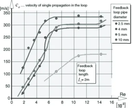
Tesař et al.31 studied a sonic fluidic oscillator which can generate hybrid-synthetic jet with suction effect, as shown in Figure 1-10. The authors argued that the oscillator operates in two regimes: one is the constant Strouhal number regime at low inlet Re conditions and the other one is the constant propagation velocity regime at high inlet Re conditions.
Figure 1-In propaga where L frequen length L the main The of Strou there is approxi from th Strouha 10. A sonic flu order to cl ation velocit Lt is the len ncy. Then, a Lt / w by th n jet in the i e Srm depen uhal number a distinctly mately Re < he supply no al number re B uidic oscillato larify and ty in the fee ngth of conn a modified S e Strouhal n inlet throat dence on Re r to Reynold y different < 3500, wh ozzle, Srm i egime. Background of t or based on a b find an in edback loop a c nection tub Strouhal nu number Sr section and 2 m Sr e is shown i ds number u regime at t hich may be is apparentl
the Study and L
bi-stable diver nvariant of p ca was init 2 2 t a L f T e, T is the umber Srm w based on th d the width w fw Sr u / t Sr L w in Figure 1-usually adm the high Re e interpreted ly independ Literature Revie
rter valve dev
the investi tially define t fL oscillation was introduc he oscillatio w of this thr 2fL ut/ -11. It is app mitted25 only e range of i d as the lam dent of Re ew veloped by Tes igated phen ed by: period, and ced by mult on frequenc roat section parent that t y holds at ve nvestigation minar regim : this is the sař V. et al. 31 nomenon, t d f is the os tiplying the cy, the veloc n.
the non-dep ery low Re, n. When Re me of the jet e so-called 13 the bulk (1-4) scillation e relative city u of (1-5) (1-6) pendence and that e is low, t issuing constant
14 Figure 1-ca i Two va velocity is called by Spyr frequen pressure 11. Modified s also plotte ariation regi y increases l d the consta ropoulos38 ncy increase e is higher t B Strouhal num ed as a func imes can al linearly with ant propagat and Hayash es with the i than a critic Background of t mber Srm as a f ction of inle lso be found h inlet Re; in tion velocity hi40 that wh inlet pressur al value.
the Study and L
function of Re
et nozzle R d in this fig n the second y regime. T hen the inle
re, while th Literature Revie eynolds numbe eynolds num gure: in the d regime, th This is in acc et pressure he frequency ew er Re31 mber as sho e first regim he velocity s cordance w (or inlet fl y keeps con own in Figu me, the prop stays constan with the obse
lowrate) is nstant once ure 1-12. pagation nt which ervations low, the the inlet
Figure 1-1.4.2 The in recen as an ‘o applied flap.45-4 test.49 It been de regime5 frequen Figure 1 of the re by the resonan in the f capaciti oscillato 12. Propagati Sweepin e sweeping j nt years for a oscillating sp to the airfo 8 Recently, t was also te emonstrated 54-56 and co ncies were fo 1-13. The m ecirculation feedback c nce frequenc feedback ch ive and a p or by Khelf B on velocity de g jet Coand jet Coanda f active flow c pray device oil to delay it has been ested to redu d both expe ompressible found by Go main frequen n bubble req channel in cy, was of th hannel. Thi propagative faoui et al.58 Background of t evelopment as da fluidic o fluidic oscil control appl e’. It was fir
the flow se applied on uce the drag
erimentally1 e regime w osen et al57 ncy was of t quired to pr this recirc he order of is bi-freque e effect, w 8.
the Study and L
s a function of oscillator llator, as sho lications, th rstly used to eparation an the vertical g on a rectan 10 and num with maxim 7 in the spe the order of rovoke the j culation bu 3000 Hz an ency pheno was also fou
Literature Revie
f inlet Re, for
own in Figu hough it was o suppress th nd improve l tail of a B ngular bluff merically52 5 mum outlet ctra of the f 500 Hz, re jet switchin ubble. The nd linked to omenon link und in the ew different feed ure 1-8, has b s initially pa he cavity re the perform oeing 757 p body 35, 50, 5 53, both in t Mach nu oscillation s elated to the ng and to th second freq the pressur ked to the study of a
dback tube dia
been widely atented by S esonance44, mance of air plane in a re 51. It’s effici the incomp umber of 1 signals as s e volumetric he flow rate quency als re wave prop co-existen monostable 15 ameters31 y studied touffer43 and then rfoil and eal flight ency has pressible 57. Two shown in c growth injected o called pagation nce of a e fluidic
16 Figure 1-supply ra The in the ou is only pressure flow rat fluidic o Figure 1-1.4.3 The 1-6b and that its o 13. Frequency ates57 e oscillator’ utlet nozzle independen e is higher. te condition oscillators ( 14. Oscillatio Pulsing j e basic geom d it was firs oscillation p B y spectra of di s main frequ e as shown i nt of the su The frequen ns. This kin (cf. Figure 1 on frequency a jet relaxati metry of a ty stly patented performanc Background of t ifferential sign uency is plo n Figure 1-upply rate w ncy increas nd of freque 1-12). as a function o ion fluidic o ypical pulsi d by Warren e is a functi
the Study and L
nal between sy
otted versus 14. It can be within a lim ses with the ency variati
of the supply r
oscillator
ing jet relax n32 as a “neg ion of the p Literature Revie ymmetrically s the supply e clearly ob mited range inlet pressu on pattern i rate 57 xation fluidi gative feedb ressure of th ew paired pressu flowrate an bserved that e when the ure almost l is very simi ic oscillator back oscillat he fluid pow
ure taps for inv
nd the Mach the main fr inlet flow linearly in l milar to that r is shown i tor”. It was wer source, vestigated h number requency w rate or low inlet of sonic n Figure declared the area
of the at employe In th a Suppl loops). T working where τ switchin speed o speed o empiric Figure 1-interactio Exp by hot w working a functio oscillati compres flowmet stagnan or swee ttached-wal ed, etc. But he work of ly input (S) The authors g material: τt is the tra ng time that f wave prop of sound), u al constant 15. Geometric on region, and periments w wire anemo g material. F on of the ga ion frequenc ssible condi ters. When nt, which is eping jet Co B ll region, th t no specific Simoes et a , an interac s proposed a ansmission t t depends on pagation (if u is the velo which has a cal characteris c) configurat were carried ometers, an Figure 1-16 as mass flow cy increases itions (e.g., n the inlet similar to t anda fluidic Background of t he distance f c function w al. 59, as show ction region an equation
1 2 t f τ time of the n the jet vel f the duct is ocity of maia value betw
stics of Simoe ions with feed
out to test nd with diff shows the e w rate, with s with the v , supply flo flow conti the response c oscillators
the Study and L from the po was propose wn in Figur , two Outpu to predict th
1 1/ 2 s τ e pressure w locity, Lf is not small, t in jet, l is t ween one an es' device: a) m dback arms of their behav ferent gases experimenta the length o olumetric fl ow less than inues increa e pattern of s (cf. Figure Literature Revie wer nozzle d. re 1-15, the m uts (O), and he oscillatio 2(Lf ξl) c u wave throug the Feedbac the speed of the nozzle-t nd two. main parts of t f different leng viors, especi s (nitrogen, al evolution of the feedb flow rate in i n 200 sccm asing, the f sonic fluid e 1-14). ew to the splitt microfluidic d two Feedb on frequency gh the feedb ck Loop Len f wave prop to-splitter d the device, b) gths59 ially their os argon and n of the osci back arm as incompressi m), these dev frequency dic oscillatoter, the type c oscillators back Arms y, in case of back loop, ength (FBL) pagation ten distance and detail of the scillation fr carbon dio illation frequ a paramete ible and mo vices can be becomes r ors (cf. Figu 17 e of fluid s include (FA) (or f gases as (1-7) τs is the ), c is the nds to the d ξ is an requency oxide) as uency as er. As the oderately e used as elatively ure 1-12)
18 Figure 1-Cer This pul like the airfoil 63 Figure 1-Acc parts: o feedbac whose k width, s capacito oscillato 16. Oscillatio rretelli et al. lsing jet rela
flow contro 3. 17. Pulsing je cording to t one is the s ck network. key geomet same nozzl or volumes. or B. B on frequency a 8 studied a s axation fluid ol in a hump et relaxation fl the authors, switching o Two oscill trical param le depth an . Oscillator Background of t as a function o similar fluid dic oscillato p diffuser 60, luidic oscillato the operati of the bi-sta lators were meters are su nd same ex A has a cap
the Study and L
of FBL Lf59 dic oscillato or has been 61, the separ or: switching ion of this able amplif designed a ummarized xit channel apacitor volu Literature Revie or whose sch successfully ration contr mechanism. P kind of osc fier, and the and named in Table 1-width, but ume which ew hematic is sh y tested in v rol on wind t Ps indicates the cillator can e other is t Oscillator A -2. They ha very differ is 20 times hown in Fig various appl turbine blad e supply total be analyze the respons A and Osci ave the sam rent feedba s larger than gure 1-17. lications, des62 and pressure8 d in two se of the llator B, me nozzle ack loop n that of
Table 1-2 E C The of both velocity pressure describe pressure These d Figure 1-oscillator In th respons frequen 2. Features of t Nozzle wi Nozzle de Exit channel Capacitor vo e measured oscillator A y for both e-controlled ed above e-insensitiv different freq 18. Frequency r A, b) oscillat he experime e is plotted cy increase B
the fluidic osc
idth epth width olume frequency r A and B are oscillators d as its freq (cf. Figu e and oper quency resp y response to tor B 8 ental study d as a functi s proportion Background of t cillators in Ce O responses to shown in F can reach quency varie ure 1-14, ates at a co ponses have inlet pressure of Tesař an ion of the in nally to the
the Study and L
erretelli’s study Oscillator A 0.050 in. 0.120 in. 0.055 in. 0.320 in3 o the inlet p Figure 1-18 h about 200 es with the Figure 1 onstant freq e not yet bee
e and sampled d Peszynsk nlet mass fl e inlet mas f Literature Revie y 8 A ressure and . It can be o 0 m/s. How inlet press 1-16), wh quency in t en clearly ex velocity signa i on this kin low rate(cf. flow rate, w ew Os 0 0 0 0 d the sample observed th wever, osci ure which ile oscillat the same in xplained. al by hot wire nd of oscilla Figure 1-1 which is com scillator B 0.050 in. 0.120 in. 0.055 in. 0.016 in3 e jet velocity hat the maxi
illator B is is similar ator A is nlet pressur e measuremen ator64, the fr 19). In this c mpletely dif 19 y signals imum jet s almost to those almost re range. t, a) requency case, the fferent to
20 what wa No reas behavio Figure 1-1.4.4 Khe oscillato Figure 1 Figure 1-Thi allow th authors as observed onable phy ors observed 19. Measured Other ki elfaoui et a or both num 1-20. 20. Sketch of s kind of os he suction o experimen B d by Simoes sical explan d between th d oscillation fr inds of Coa al.58 studied merically and f a mono-stabl scillator has f a secondar ntally and n Background of t s et al59 (cf. nation has b he various o requency as a anda oscilla d the mecha d experimen e fluidic oscil s only one fe ry fluid by t numerically
the Study and L Figure 1-16 been propos oscillators d function of th ator anism of th ntally. The s llator based on feedback loo the control p y studied th Literature Revie 6) and by C ed yet to ex described ab he inlet flow ra he jet switc schematic of n an amplifier op. One of t port C2 for m hree differe ew Cerretelli et a xplain the st bove.
ate, with diffe
ching in a m f the studied r 58 the interests micro-mixin ent configur al8 (cf. Figu strong differ erent FBLs 64 mono-stable d device is s s of this des ng applicati urations in ure 1-18). rences in e fluidic shown in sign is to ons. The order to
explain pressure examine Two demons volume main on in the fe Tes Figure compare and exp channel open in sudden switchin indepen an array oscillato Figure
1-1.5
It h periodic its behavio e, oscillatio ed the oscill o oscillation strated that t connected ne, is driven eedback loo ař et al65 pr 1-21. The m ed to the ab pansion wa l which is c nto atmosph change in ng frequenc ndent of the y of this kin ors without 21. New ideaEfficie
has been dem c fluidic ex B r. They poin on frequenc lation mode n modes w the main os to the clos n by a propa op. roposed mo main featur bove mentio ves in the connected t here. The je pressure, cy is mainl mass flowr nd oscillator modifying of fluidic osc
ent separ
monstrated xcitations is Background of t nted out the cy, threshol es in detail. ere found, scillation is ed branch w agative effec ore recently re of this ne ned oscillat resonance to the contr et oscillation traveling fo ly determin ate passing r synchroniz the resonan cillator proposration co
by numerou much morthe Study and L e relationshi ld pressure similar to t controlled while the se ct, in relatio y a new con ew design i tors. Its jet s channels. A rol terminal n is caused forth and b ned by the through the zed since it nce channel sed by Tesař e
ontrol by
us researche re efficient, Literature Revie ips between e levels and the findings by a capaci econdary os on with the ncept of flui is the absen switching is As shown i X1 is close d by weak s back throug length L o e oscillator. is difficult working dy t al.65y periodi
es 6, 66-68 tha with a gai ew key parame d geometric s of Gosen itive effect, scillation, s propagation idic oscillat nce of feedb s controlled in Figure 1 ed, and the shock wave gh the reso of the reso However, i to make an ynamics.ic jets
at active flo in of as hig eters such a cal parame et al57. It w in relation superimpose n of pressur tor, as illus dback loop c by the com 1-21, the re other chann es generated onance chan onance chan it is difficult ny link betw ow control b gh as two o 21 as supply ters and was thus with the ed to the re waves trated in channels mpression esonance nel X2 is d by the nnel. Its nnel and t to keep ween two based on orders ofBackground of the Study and Literature Review
22
magnitude in terms of added momentum coefficient compared to control based on steady blowing. For the purpose to evaluate and compare the efficiency of an injection jet on the separation control, two dimensionless numbers, the injection momentum coefficient Cμ and the velocity ratio VR, are defined.
For steady blowing,
2 1 2 b b μ m U C ρU Lω (1-8) b R U V U (1-9)
where ω is the span width of the controlled flow, mb is the blowing mass flow rate, Ub is the blowing velocity, and L is the flow characteristic length. For unsteady injection, the mean values of momentum added are used to calculate Cμ, while the maximum blowing velocity
max b U is used to calculate VR : 2 1 2 b b μ m U C ρU Lω (1-10) max R b V U U (1-11)
In most of the previous works, L is the distance between the injection location and the diffuser trailing edge 69 or the reattachment point70-72, but it may also be defined as the ramp heights73, 74. In the present work, L will be defined as the length between the ramp slant edge and the separation point.
In the unsteady injection case, a dimensionless injection frequency F+ is also defined: /
F fL U (1-12)
where f is the oscillation frequency, U∞ is the free stream velocity.
Since the fluidic oscillators developed in this thesis aims to be applied to the flow separation control on a ramp, the key parameters of some representative works on ramp or hump flows are listed in Table 1-3. Large discrepancies can be observed between the optimal values of some of these parameters, especially Cμ, found by the different groups, which can be explained by the differences in the studied configurations(e.g., geometry of the ramp or the hump, position and orientation of the controlling jets, etc.). However, the optimal values found for the velocity ratio VR are between 2 and 3 for all the studies and the optimal F+ is about 1 in a majority of cases. It was also found in the study of Seifert et al 70, that the superposition of weak suction on the periodic excitation enhances the control efficiency.
Background of the Stud y and Literatur e R eview 23 Ta bl e 1 -3 . Key pa ram et ers of rep rese nt at iv e st udi es on se pa rat io n co nt ro l of ram p o r hu m p fl ow authors flow type actuation method U∞ m/s Cμ VR range F + range Optima l Cμ Optima l VR Optima l F + Cerretelli et al. 61 Hu m p dif fuser Discrete stead y bl owing 2.16 0 - 6% (0,7.7) -- 4% 2 -- Cerretelli et al. 69 Hu m p dif fuser Fluidic oscill ator 25.9 0 - 6% 8 0.6 - 5 5% -- 0.7 V ikas et al. 75 Straford ram p Discret e steady blowing 40 - 60 -- (8,10) -- -- -- -- Seifert et al. 70 W all-Mounted Hum p Slot steady bl owing 85 -- -- -- 2% 2 -- Slot steady su ction 0-4% -- -- 0.8% 1.26 -- Oscillatory excitation -- -- 0.4-2.0 -- -- 1.6 Greenblatt 71, 72 W all-Mounted Hum p Slot steady su ction 34 0.24% 0.81 4 -- -- -- --
Slot zero mass flux Oscillatory
excitation 13.6 – 4 0.8 0.01% -3% 0.65 - 2 0.45-1 .94 -- >1 1.05-1 .35 Zhang et al 73 Tw o-Dimensional Ram p Discrete sy nt hetic jets 6.5 -- 0.63 - 1.57 0.8 -2.4 -- -- -- Kourta et al 76, 77 Tw o-Dimensional Ram p
Discrete pulsed jets
20 0.16 5% 3 0.79 5 & 1.98 -- -- -- Joseph et al. 74 T w o-Dimensional Ram p Di scret e pulsed jets 20 - 40 0.08% - 1.9% 2-6 0.1 - 4 1.9% -- 2.7