HAL Id: hal-01165286
https://hal-mines-albi.archives-ouvertes.fr/hal-01165286
Submitted on 18 Jun 2015HAL is a multi-disciplinary open access archive for the deposit and dissemination of sci-entific research documents, whether they are pub-lished or not. The documents may come from teaching and research institutions in France or abroad, or from public or private research centers.
L’archive ouverte pluridisciplinaire HAL, est destinée au dépôt et à la diffusion de documents scientifiques de niveau recherche, publiés ou non, émanant des établissements d’enseignement et de recherche français ou étrangers, des laboratoires publics ou privés.
Method for the Design of a Contact Dryer-Application
to Sludge Treatment in Thin Film Boiling
Didier Lecomte, Olivier Fudym, Christine Carrere Gee, Patricia Arlabosse, J.
Vasseur
To cite this version:
Didier Lecomte, Olivier Fudym, Christine Carrere Gee, Patricia Arlabosse, J. Vasseur. Method for the Design of a Contact Dryer-Application to Sludge Treatment in Thin Film Boiling. Drying Technology, Taylor & Francis, 2004, 22 (9), p.2151-2172. �10.1081/LDRT-200034229�. �hal-01165286�
METHOD FOR THE DESIGN OF A CONTACT DRYER - APPLICATION TO SLUDGE TREATMENT IN THIN-FILM BOILING
D. Lecomte1, O. Fudym1, C. Carrère-Gée1, P. Arlabosse1 and J. Vasseur2
1
LGPSD UMR CNRS 2392 - Ecole des Mines d’Albi Carmaux, Route de Teillet, 81013 Albi, France
2
ENSIA – INRA – Département Génie Alimentaire, 1 Av. des Olympiades, 91305 Massy Cedex, France
Email: lecomte@enstimac.fr
ABSTRACT
A method, based on the analysis of heat transfer is developed for the design of contact dryers in thin film boiling for sludge treatment. An experimental device was built in order to estimate the heat flux density exchanged between a hot metallic plate and the drying sample. This specific device is made of a thick copper plate heated at a temperature above 100°C, on which the sludge is coated. The contact temperature and the heat flux density are estimated using a temperature sensor inside the copper block and an inverse conduction method (Beck's sequential function specification method). The corresponding drying curve is deduced from an energy balance. Sludge drying was studied on an
electrically heated laboratory continuous drum dryer. A simple steady state model of the drum dryer was developed by taking into account the combined effects of internal and external transfers. This model is validated by comparison with drying curves obtained from sampling and simulation. In this case, the relative importance of internal and external heat transfers is highlighted.
Key Words: Drum dryer; Heat and mass transfer; Industrial sludge; Inverse conduction problem; Thin-layer boiling.
INTRODUCTION
A comparative study of dryer technologies currently used for sludge treatment has shown that their development is limited by high energy costs and technological problems like small heat transfer rates, fire hazards and handling difficulties due to sludge stickiness and hardening behaviour (also called plastic phase) at critical moisture contents [1, 2]. Indirect drying or contact drying, applied to the thermal treatment of sludge, presents many advantages: steam and odour confinement, VOC concentration, volume reduction, higher energy efficiencies [1, 3].
Among contact-drying technologies [9], drum drying is widely used in the food industry to treat heat-sensitive products. The product is sprinkled or coated on a hot rotating cylinder. The wall temperature is above the boiling point of the product. The absence of mixture and agitation constitutes an advantage for viscous products like pastes or sludge, enabling a good control of the residence time, average final water content and thermal efficiency [4, 5]. The drying time is very
short (around ten seconds in an industrial dryer) with very high heat flux densities. However this drying process has limitations due to large volume/surface ratio (it cannot be used for drying large quantities) and the small residence time may not ensure full stabilization if pathogens are abundant.
Numerous studies on drum drying [6-10] have been published regarding food-processing dryer control but little was found on the mechanisms of coupled heat and mass transfer during coating and on the drying rates and heat flux at the metal/product interface. Heat and mass transfer between a heated wall and a sludge result from coupled internal and external heat transfer. Internal heat transfer is influenced by the boiling mechanism in the sludge, external heat transfer is dependent on both the process and the heating medium.
This study is divided into two parts :
- An experimental determination of internal heat and mass transfer rates between a heated wall at a known temperature and a thin film of sludge under vaporization;
- The development of a simple serial resistance model for coupled internal and external heat transfer and computation of drying curves using an energy balance.
CHARACTERIZATION OF INTERNAL TRANSFERS Principle of the Experimental Device
The first objective of the experimental device is to provide thermal conditions for thin-film vaporisation contact drying. In order to supply and measure high flux densities (105-106 W.m-2) an original experimental device was designed and built. The principle of the experiment is to heat up a plate of metal and store the corresponding energy at a temperature above the boiling
point of water (100°C). The heat is suddenly discharged when the plate is coated with the sludge (thin film 0.7 mm) which is rapidly heated up to the boiling temperature.
The plate must be thick enough in order to store the necessary amount of energy for a complete drying by vaporisation. It must be highly diffusive in order to ensure high heat-flux densities at the metal/sludge interface. Copper was chosen for its high thermal diffusion properties. The plate dimensions are 200 mm * 288 mm * e=58 mm.
Instrumentation of the Plate
In order to achieve an energy balance of the drying sludge, the interface heat flux between the drying product and the heated surface has to be determined.
Preliminary tests [11] showed that no direct temperature or heat-flux measurement could be made at the interface: a sensor located on the front side would disturb the sludge coating or introduce a thermal contact resistance.
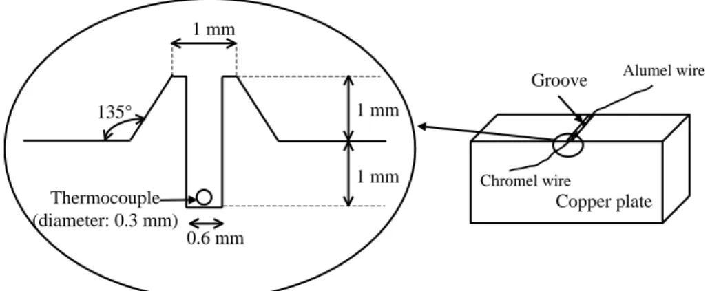
In order to measure the temperature as close as possible to the interfacial wall, two thin leads of chromel and alumel are laid inside a special groove made on the front side of the copper plate and the metal is then cautiously hammered. According to copper plasticity, the prominent part (see Figure 1) partly fills up the groove. The front surface is ground to obtain a true surface. The contact between the leads and the copper block is excellent as seen on Figure 2 and, with this particular method, the sensor location is precisely known. The resulting thermocouple K, with separated contacts, is laid in a direction parallel to the isothermal curves (Y1 on Figure 3).
The back side is insulated with mineral wool to reduce heat losses. Another sensor is laid out on the plate back side (Y2 on Figure 3) to verify this boundary condition.
The measured temperature Y1 can be very different from the wall temperature Tw, due to the large
interface heat-flux density near the boundary of the front plate surface. The wall temperature and heat flux density q are then estimated from an inverse heat conduction method using the information provided by the thermocouple measurements Y1.
Interfacial Heat-Flux Density Estimation Method
A model ([1], [11- 12]) was built in order to solve the direct problem and calculate the change in temperature at the sensor location, due to a given input heat flux applied on the plate’s surface. Heat transfer is assumed to be one dimensional and the plate back side is assumed to be insulated: t T a 1 x T 2 2 (1a)
with the boundary and initial conditions:
q x T k 0 x (1b) 0 x T k e x (1c) 0 T T 0 t (1d)
The goal of the direct model is to find the temperature variable T1 at the sensor location x = e1, as
a function of the « input » heat flux density q. Of interest is also to find the back side temperature
T2 at x = e, and the interface wall temperature Tw. The thermal quadrupole approach yields a
convenient method to compute this kind of direct relationships [13- 15]. A Laplace transform is applied to the temperature and to Eqs. (1b-c), such as:
0 st 0)e dt T T ( (2)
Solving Eqs. (1a-d) in the Laplace space yields the relationships between the temperature variables and the input heat flux density - see [15] for more details - such as:
1 F1 (3a) 2 F2 (3b) w Fw (3c)
where 1,2,w and are the Laplace transforms of T1,T2,Tw and q, and the corresponding transfer functions are found as:
) Ke sinh( bs ) Ke cosh( ) s ( F 2 / 1 1 1 (4a) ) Ke sinh( bs 1 ) s ( F 2 / 1 2 (4b) ) Ke tanh( bs 1 ) s ( F 2 / 1 w (4c) with a s K
An inverse method [1, 16] allows the heat flux density q(t) to be calculated from the measured temperatures Y1(t) at the sensor location and the corresponding computed temperature T1(t) from
the direct model. In the case of the one-dimensional problem with fast and high heat-flux changes, a sequential method is adapted. The function specification method with a sequential constant heat-flux functional form is used [17, 18]. The heat flux density is discretized, and for
each time, the new heat flux increment is deduced in a sequential form from a least square procedure. The stabilization of the solution is obtained through the future time steps concept [18].
The transfer function defined in Laplace space by Eq. (4a) is inverted from a numerical Laplace inversion [19]. Then the temperature T1 is deduced from Eq. (3a) by a convolution product, such
as t 0 1 1(t) q(t ).f ( )d T (5)
where f1(t) is the inverse Laplace transform of F1(s).
The insulated boundary condition will be validated by comparison of T2 with the measured
temperature Y2 of the back side of the copper block..
Heat-Flux Estimation and Temperature Results
Results are presented for thin-film coating of an alumina hydroxide sludge on a copper plate. The initial water concentration of the sludge is identical in all experiments.
The plate is heated up in a convective kiln, and a stable initial temperature T0 above the product’s
boiling temperature is reached before the experiment is started. At time t = 0, the product is rapidly coated on the plate, while Y1 and Y2 are recorded.
Many experiments have been done, but the goal of the present paper is only to present the general work and method, and the results are exhibited only for two cases, with initial temperature T0
equal to 138°C and 114°C. The analysis of Eqs. (1-5) shows that the thermal properties of the plate should influence the heat transfer.
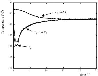
The evolution of the measured and computed temperature changes is plotted on Figure 4 for
T0 = 138°C. The measured temperature Y1 fits perfectly with T1, but this is directly due to the
inverse method which is very close to an exact matching algorithm. A more important aspect is the good fit between the back side measurements Y2(t) and the corresponding computed
temperature T2(t) which means a good agreement between the experimental data and the model,
and confirms the validity of the assumption of back side insulation. The wall temperature Tw and
the computed temperature T1 are almost identical, except for high flux densities.
The temperature Y1 shows a straight decrease (12°C) due to sudden boiling phenomena, and the
corresponding superficial high heat flux density. The decrease ends when the heat-flux intensity falls while thermal diffusion inside the copper plate tends to keep it homogeneous. When q(t) is turned to be very low, front-side and back-side temperatures reach the same value, corresponding to a state of quasi-equilibrium.
The back side temperature Y2 shows a slow decrease due to thermal diffusion through the
thickness of the copper plate after a first period where Y2 is assumed to be constant. At the end of
the experiment ( t = tf ), the two temperatures Y1 and Y2 are equal. The copper plate temperature
is homogeneous.
The wall temperature Tw is always above the product boiling point. Boiling comes to an end,
probably due to some changes in the product structure: a large internal thermal resistance is found at the interface between the dried product and the plate.
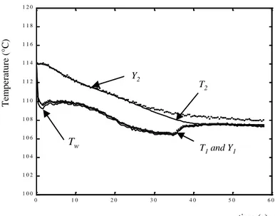
Figure 5 shows computed and measured temperatures for T0 = 114 °C. The temperature Y1 shows
a first temperature decrease ( 4 °C) due to boiling phenomena followed by a stabilisation. The change in Y2 is similar to that observed in the previous experiment. However, after 30 seconds,
the two temperatures T2 and Y2 are different. Whereas the computed temperature T2 is reaching
the front side temperature, the experimental temperature Y2 is slightly higher ( + 0.5 °C ). This
difference may be due to the effect of heat losses which were assumed to be negligible in the model but can be observable at steady state.
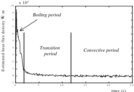
Figure 6 shows boundary heat-flux density q(t) estimated from Y1 measurements with
T0 = 138 °C. A high value, about 106 W.m-2, is obtained after a very short time, less than one
second, due to strong boiling phenomena. The flux decrease is followed by an evaporative drying period, involving smaller heat transfer. The rate of evaporative transfer cannot be estimated with precision as it is very small compared to heat transfer during boiling. The transient period between boiling and evaporation drying is more or less defined.
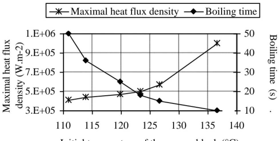
When the initial temperature of the copper plate T0 is closer to the product boiling point, the
boiling time is longer (Figure 7) but the maximal heat-flux density is lower.
Energy Balance and Drying Curves
The interfacial heat flux density can be used to calculate the energy density E generated during the process: t 0 d ) ( q ) t ( E (6)
The global energy density lost by the copper plate between the initial state and the final quasi-steady state (when front-side and back-side temperatures are equal to the final temperature Tf
defined in the previous section) is:
) T T ( e C ' E p 2 f 0 (7)
E’ is found to be quite close to E(tf), where tf is the final time defined by T1 T2 Tf (Table 1).
This means that q(t) is the main flux crossing the plate walls and confirms the assumption about the insulated back side. This result also seems to prove there are no lateral fluxes. Hence the one-dimensional conductive transfer assumption is valid.
The dry matter load can be deduced from Eqs. (6-7), such as
v f 0 W )l W ( ' E M (8)
where W0 and Wf are the initial and final moisture contents (experimentally determined at t = 0
and t = tf). The drying rate is highly dependent on the dry matter load M but it is difficult to make
accurate measurements of this quantity. Using Eq. (8) seemed to be a more relevant method to determine M than direct experimental measurements based on sampling of the sludge before and after drying.
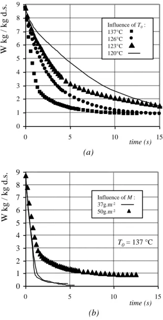
The moisture content W(t), the drying curves, and finally the drying rate can be deduced from Eqs (6-8): v 0 .l M ) t ( E W ) t ( W (9)
Some drying curves are shown on Figure 8. It is noticeable that thin-layer drying by boiling, in this particular case, is very fast, because as long as boiling occurs, external transfer is not the limiting phenomena. The drying time increases with initial temperature and with dry matter load. The final water content, except in two experiments (where the dry matter load is very low), is near 1 kg.kg-1 dry solid. This water content is satisfactory for alumina sludge treatment. Below
this value, water is bound to the solid by adsorption and the sludge becomes a good insulating material.
Internal Thermal Resistance
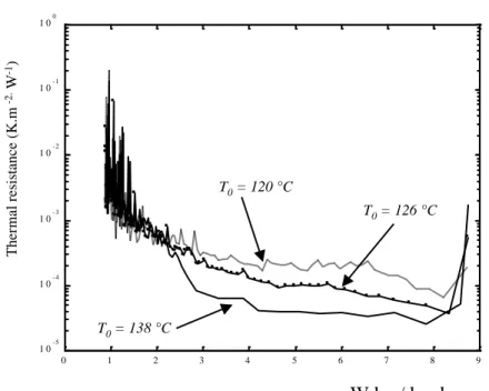
Knowing the interface heat flux density and the wall temperature, a thermal resistance can be defined between the boiling sludge and the hot metal interface. This thermal resistance is called "internal" because it is mainly controlled by internal transfer and adsorption forces in the sludge.
t q T t T t Rint w b (10)where Tb , the boiling point temperature of the sludge, is assumed to be equal to the boiling point
of water, 100°C. This assumption is valid for W > 1 kg.kg-1 d.s.[1].
The internal thermal resistance is plotted versus the water content W on Figure 9. Its values are small for hard boiling (at the beginning of the contact), but they rise by several orders of magnitude during the drying process.
For the drum dryer model presented in the next section, a parametric empirical relationship is needed for the internal thermal resistance calculated from experimental data with Eq. (10). The corresponding experimental curves are fitted with the following 6 parameters function [1]:
K W e KW K W Ke W R b T a T W R b T a b T a m ' ' 1 ' 1 ' , 1 0 1 1 0 1 2 0 2 0 int (11) with W'1W/WO.The resulting estimated parameters are presented in Table 2.
DRUM DRYER MODELLING AND EXPERIMENTAL VALIDATION Drum Dryer Description
In this part, the drying of alumina sludge on an electrically heated laboratory drum dryer was studied (Figure 10 and Table 3). The drum dryer (212 mm in diameter and 250 mm in length) is composed of an internal cylinder made of copper (201 mm in diameter and 117 mm in length) and of an external sheet made of stainless steel. Twelve cylindrical heating resistors are set uniformly in the copper cylinder. The cylinder temperature is controlled by a PID controller. Four Pt100 probes are located inside the copper cylinder (cf. Figure 10). The temperature is limited to 180°C.
Experimentation
The drying kinetics are obtained by manual sampling at different positions on the cylinder surface. The samples are oven dried at 105°C until equilibrium is reached and the drying curves can be compared with those obtained with the "copper plate" experimental device.
The curves are similar whereas the drying time for drum drying is much longer and depends on temperature settings. This difference is due to external heat transfer by conduction between the heating elements and the sludge/metal interface. Comparisons will be presented in the next section.
Drum Dryer Modelling
The simple model developed for drum drying is based on thermal resistance in series (Figure 11) and takes into account the coupled effects of external and internal transfers at steady state. This model enables heat conduction to be simulated through the various metal layers constituting the laboratory drum dryer (Figure 12). The energy provided to the alumina sludge by the drum dryer is used to vaporise the water contained in the sludge.
The main assumptions for the resistive model are:
A1: The sludge temperature and water content are independent of the radius A2: Axial heat transfer is neglected
A3: Heat transfer by convection and radiation is neglected
A4: External thermal resistance of the drum dryer is assumed constant during drying. This
external resistance includes the thermal resistance of the steel jacket, the contact resistance between the copper and the stainless steel and the thermal resistance of the copper layer. An average thermal resistance of the drum dryer is estimated to 4.10-4 K.m2.W-1.
A5: The temperature is assumed to be homogeneous, constant and equal to the temperature
setting in the copper. Therefore the thermal resistance within copper can be neglected.
A6: Thermal inertia of the different layers is neglected. It is a simplistic assumption which is not
valid during transient states. However, this assumption can be kept for design purpose.
A7: The expression of Rint(W,Tw) is assumed equal to Rint(W,T0) established in the previous
section with the initial temperature of the copper plate (T0).
A8: The drum linear speed, v, is supposed to be constant, such as
t . v
Mathematical Expression of the Drum Dryer Model and Results The losses being negligible, it is assumed that:
vl M dy dW M l dt dW y q v v (13)The relation between the heat flux density and the temperatures Tb and Tc is:
w int ext c b ext c w T , W R R T T R T y T y q (14)This system of partial differential equations is solved by the Runge-Kutta method, using the function “ ODE 45 “ by MATLAB™ [20]. For each step, this model calculates the wall temperature Tw, the interfacial heat flux density q(y), the internal thermal resistance Rint and the
sludge moisture content W.
For Tc = 140 °C, the maximum heat flux density obtained by the drum-dryer model (Figure 13) is
about two orders of magnitude smaller than the maximum heat flux density obtained with the "copper plate" device (Figure 6). Nevertheless, the duration of this maximal value is about 10 seconds, compared to less than 2 seconds with the "copper plate" device.
The external thermal resistance is greater than the internal thermal resistance until
W = 1 kg.kg-1dry solid (Figure 14) that is for most of the drying process. So, external heat
transfer clearly controls the drying time. For this simulation, the drying time is about 15 seconds (Figure 15).
Figure 15 shows the evolution of the moisture content obtained experimentally and by simulation for Tc =140°C. In spite of the important sources of errors due to experimental sampling, a good
neglecting losses by convection, the model is not satisfactory for the final stage of drying. However it gives a good prediction of the drying time for design purposes.
CONCLUSION
An original method to determine exchange coefficients for contact drying was developed and experimentally validated. This method allows the contact drying curve to be determined for a thin-layer using thermal measurements associated with inverse techniques.
The study of the heat transfer shows a first phase (strong boiling period) with very strong flux densities, followed by a transition phase, and finally by a phase of weak flux densities. This phase corresponds to the end of the drying process and the formation of an insulating layer at the surface of the metal.
The extrapolation of these results was made on a laboratory drum dryer by taking into account the external transfers (conduction through the cylinder). A simplified model was developed and validated on the basis of experimental results.
It was shown that alumina sludge, which is a very hygroscopic and colloidal product, could be dried in a short time (15-20 s) to an end value compatible with industrial demand (storage or co-incineration in a cement factory). In thin layer contact drying, as opposed to convection drying, internal transfer is not the limiting phenomenon: conduction heat transfer in the heating device controls the drying time . It could be considerably reduced by a better design of the heat source. The developed method can be applied for the design of indirect dryers using thin-film boiling techniques for food or sludge treatment.
NOTATIONS
a Thermal diffusivity m2.s-1
b Effusivity W.m-1.K-1.s1/2
e1 Sensor location in copper plate m
e Copper plate thickness m
E Energy density J.m-2
E’ Global energy density J.m-2
f(t) Inverse transfer function -
F(s) Transfer function -
k Thermal conductivity W.m-1.K-1
lv Water latent heat of vaporisation J.kg-1
M Dry matter load kg.m-2
q Interfacial heat-flux density W.m-2
Rext External resistance K.m2.W-1
Rint Internal thermal resistance K.m2.W-1
s Laplace variable s-1
t Time s
T Temperature °C or K
Tb Boiling temperature °C or K
Tc PID controller temperature °C or K
W Dry basis moisture content kg.kg-1 d.s
x, y Space variables m
Y Measured temperature °C or K
Greek letters
Laplace heat flux density -
Laplace temperature - Subscript 0 Initial Value 1,2 Sensor locations f Final value w Wall
ACKNOWLEDGEMENTS
The authors would like to thank J.-C. Poussin and B. Auduc for lending their technical support to this work.
REFERENCES
1. Carrère-Gée, C. Etude du séchage indirect d’une fine couche de boue d’hydroxyde d’aluminium en ébullition – Application au cylindre sécheur. PhD Dissertation 1999, Université P. Sabatier de Toulouse, France, 250 p.
2. Chen, G. ; Yue, P.L. ; Mujumdar, A.S. Sludge dewatering and drying. Drying Technology
2002, 20(4&5), 883-916.
3. Ferrasse, J.H.; Arlabosse, P.; Lecomte, D. Heat, momentum and mass transfer measurements in indirect agitated sludge dryer. Drying Technology 2002, 20(4&5), 749-769.
4. Mujumdar, A. S. Handbook of industrial drying. (Second edition). Marcel Dekker, Inc., New York , 1987
5. Vant Land, C. M. Industrial drying equipment – Selection and application. Marcel Dekker, Inc., New York, 1991
6. Rodriguez, G; Vasseur, J.; Trystram, G. Automatic control of drum drying of food. Drying
1994, A, pp. 479-486
7. Vasseur, J. Etude du séchage d’un produit visqueux, en couche mince, sur une paroi chaude, permettant de définir un modèle de séchoir sur cylindre. PhD Dissertation 1983, Ecole Nationale Supérieure des Industries Agricoles et Alimentaires, France
8. Vasseur, J.; Loncin, M. High heat transfer coefficient in thin film drying. Engineering and food 1984, pp. 217-225
9. Daud, W.R.B.W.; Armstrong, W. D. Residence time distribution of the drum dryer. Chemical Engineering Science 1988, 43(9), pp. 2399-2405
10. Kessler, H. G., Food engineering and dairy technology, A. Kessler Ed., Freising, RFA, 1981
11. Carrère-Gée, C.; Lecomte, D.; Fudym, O., Ladevie, B.; Vasseur, J. Determination of heat flux in thin-layer drying of sludges. Proceedings of the 11th International Drying Symposium 1998 (IDS’98), Halkidiki, Greece, A, pp. 695-702
12. Fudym, O.; Carrère-Gée, C.; Lecomte, D.; Ladevie, B. Heat flux estimation in thin-layer drying. Proceedings of 3rd icipe 99, In Inverse Problems in Engineering: Theory and Practice,
13. Degiovanni, A. Conduction dans un "mur" multicouche avec sources: extension de la notion de quadripôle. Int. J. Heat Mass Transfer 1988, 3, pp 553-557
14. Batsale, J.C. ; Maillet, D. ; Degiovanni, A. ; Extension de la méthode des quadripôles thermiques à l’aide de transformations intégrales: calcul de transfert thermique au travers d’un défaut plan bidimensionnel. Int. J. Heat Mass Transfer 1994, 37, pp 111-127
15. Maillet, D. ; André, S. ; Batsale, J.C. ; Degiovanni, A. ; Moyne, C. Thermal quadripoles : Solving the heat equation through integral transforms. John Wiley, 2000
16.Fudym, O., Carrère-Gée, C.; Lecomte, D.; Ladevie, B., Drying kinetics and heat flux in thin layer drying. International Communications in Heat and Mass Transfer 2003, 30(2), pp. 333-347.
17. Beck, J.F. Nonlinear estimation applied to the nonlinear inverse heat conduction problem. Journal of Heat Mass Transfer 1970, 13, pp. 703-716
18. Beck, J.F.; Blackwell, B.; St. Clair, C. Inverse heat condition, ill-posed problems. Wiley-Interscience, New York, 1985
19. Stehfest, H. Remarks on algorithm 368’, Numerical inversion of Laplace transform. A.C.M
20. Moler, C.B; Van Loan, C.F. MATLAB user’s guide: The Math Works. Inc.-21 Eliot Street - South Natick, MA 01760
TABLES
TABLE 1 – Comparison of the two calculated energy densities E' and E(tf) for various values of
the initial temperature of the copper plate
T0 (°C) E(tf) (x105 J.m-2) E’ (x105 J.m-2) 138 9.10 0.01 8.91 0.89 127 9.08 0.01 9.18 0.92 123 8.88 0.01 8.95 0.90 120 10.07 0.02 10.01 1.01 114 13.39 0.02 13.38 1.34 111 14.83 0.02 14.51 1.45
TABLE 2 – Estimated coefficients when Equations (11) is fitted with the experimental curves as shown on Figure 9
a1 b1 a2 b2 Rm K
4.23 104 -1.048 102 0.196 -4.431 10-4 1.106 8.384 10-5
TABLE 3 – Dimensions of the drum dryer
Metal Thickness (mm)
Stainless steel 5.50
Figure 1 – Profile of the groove made in the front side of the copper plate before hammering. 0.6 mm 1 mm 1 mm 1 mm Thermocouple (diameter: 0.3 mm) 135° Copper plate Groove Chromel wire Alumel wire
Figure 2 – Sensor position after hammering and surface grinding. No trace of hammering is observed due to copper plasticity. The thermocouple leads are not in contact but in vis-à-vis, creating a K thermocouple with copper as intermediate metal.
Front side Thermocouple wire Copper plate 0.7 mm 1 mm
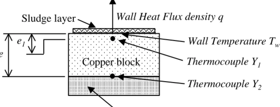
Figure 3 – Schematic experimental device Mineral wool Copper block Sludge layer Thermocouple Y1 Thermocouple Y2 Wall Heat Flux density q
e1 Wall Temperature Tw
Figure 4 – Computed and measured temperatures for T0=138°C 0 5 1 0 1 5 2 0 2 5 1 1 0 1 1 5 1 2 0 1 2 5 1 3 0 1 3 5 1 4 0 time (s) Te m per at ure (°C ) T1 and Y1 T2 and Y2 T Tw
Figure 5 - Computed and measured temperatures for T0 = 114 °C 0 1 0 2 0 3 0 4 0 5 0 6 0 1 0 0 1 0 2 1 0 4 1 0 6 1 0 8 1 1 0 1 1 2 1 1 4 1 1 6 1 1 8 1 2 0 time (s) T em p erat u re (° C ) Y2 T2 T1 and Y1 T Tw
Figure 6 – Estimated superficial heat-flux density q(t) 0 5 1 0 1 5 2 0 2 5 - 1 0 1 2 3 4 5 6 7 8 9 1 0 x 1 05 tim e (s) E s ti m a te d h e a t fl u x d e n s it y W .m -2 x 1 05 Transition
period Convective period
Figure 7 - Influence of the initial plate temperature on the heat-flux density and boiling time. 3.E+05 5.E+05 7.E+05 9.E+05 1.E+06 110 115 120 125 130 135 140
Initial temperature of the copper block (°C)
M axi m al he at f lux de ns it y ( W .m -2) 10 20 30 40 50 Boi ling t im e ( s) .
Figure 8 - Drying curves calculated using Equation (9) for (a) different initial temperatures T0 (b)
different dry matter loads M
0 1 2 3 4 5 6 7 8 9 0 5 Time (s) 10 15 W at er c o n te n t (k g .k g M S -1 ) Influence of T0 : 137°C 126°C 123°C 120°C (a) time (s) W k g / k g d. s. 0 1 2 3 4 5 6 7 8 9 0 5 10 15 Time (s) W a te r c o nt e nt ( k g .k g M S -1 ) Influence of M : 37g.m-2 50g.m-2 T0 = 137 °C (b) time (s) W k g / k g d .s .
Figure 9 – Thermal resistance as defined by Equation (10) vs. moisture content for different values of initial temperature
0 1 2 3 4 5 6 7 8 9 1 0- 5 1 0- 4 1 0 - 3 1 0- 2 1 0- 1 1 00 T0 = 120 °C T0 = 126 °C T0 = 138 °C Moisture content (kg.kg DB-1) T he rma l r e sis ta nc e ( K .m -2. W -1) W kg / kg d.s.
Figure 10 – Drum dryer schematic description Heating system Probe Pt 100 Drying shaft Copper Stainless steel Knife 212 mm Roller
Figure 11 - Electric equivalent diagram of the drum dryer model Rint(W,T) Tb Rext Tw q Tc
Figure 12 - Schematic transfer in drum dryer Sludge Copper Stainless steel q Tc Tw(y)
Figure 13 – Heat-flux density evolution versus time for Tc = 140°C ; v = 1.45 cm.s-1 ; M = 31.36 10-3 kg d.s. m-2. 0,0E+00 1,0E+04 2,0E+04 3,0E+04 4,0E+04 5,0E+04 0 5 10 15 time (s) q (W/m2) 5. 104 4. 104 3. 104 2. 104 1. 104 0
Figure 14 – Comparison between Rext and Rint for Tc=140°C. 1,0E-05 1,0E-04 1,0E-03 1,0E-02 1,0E-01 1,0E+00 0 1 2 3 4 5 6 7 Rext Rint The rmal r esi st anc e ( K .m 2.W -1) Moisture content (kg/kg d.s.) 1 10-1 10-2 10-3 10-4 10-5
Figure 15 – Experimental and simulated drying curves for Tc = 140°C, W0 =6.58 kg. kg-1 for
experiment (o) and W0 =5.5 kg. kg-1 for experiment (+). The moisture constant is expressed in
reduced form W/W0 0.0 0.2 0.4 0.6 0.8 1.0 0 5 10 15 20 25 30 35 time (s) R educ ed moistur e c onte nt W /W 0 o Experimental, M = 44.38 g.m-2 + Experimental, M = 31.36 g.m-2 Simulation, M = 44.38 g.m-2 Simulation, M = 31.36 g.m-2