This is an author-deposited version published in:
http://oatao.univ-toulouse.fr/
Eprints ID: 10955
To link to this article: DOI: 10.1002/sat.1064/
URL:
http://onlinelibrary.wiley.com/doi/10.1002/sat.1064/abstract
To cite this version:
Kuhn, Nicolas and Lochin, Emmanuel and Lacan,
Jérôme and Boreli, Roksana and Clarac, Laurence On the impact of link
layer retransmission schemes on TCP over 4G satellite links. (2014)
International Journal of Satellite Communications and Networking . ISSN
1542-0973
O
pen
A
rchive
T
oulouse
A
rchive
O
uverte (
OATAO
)
OATAO is an open access repository that collects the work of Toulouse researchers and
makes it freely available over the web where possible.
On the impact of link layer retransmission schemes on TCP
over 4G satellite links
N. Kuhn
1,2,3
, E. Lochin
1,2, J. Lacan
1,2, R. Boreli
3, L. Clarac
4Abstract
We study the impact of reliability mechanisms introduced at the link layer on the performance of transport protocols in the context of 4G satellite links. Specifically, we design a software module that performs realistic analysis of the network performance, by utilizing real physical layer traces of a 4G satellite service. Based on these traces, our software module produces equivalent link layer traces, as a function of the chosen link layer reliability mechanism. We further utilize the link layer traces within the ns-2 network simulator to evaluate the impact of link layer schemes on the performance of selected TCP variants. We consider erasure coding, ARQ and Hybrid-ARQ link layer mechanisms, and TCP Cubic, Compound, Hybla, New Reno and Westwood. We show that, for all target TCP variants, when the throughput of the transport protocol is close to the channel capacity, using the ARQ mechanism is most beneficial for TCP performance improvement. In conditions where the physical channel error rate is high, Hybrid-ARQ results in the best performance for all TCP variants considered, with up to 22% improvements compared to other schemes.
1
Introduction
The use of satellite networks by mobile users has greatly increased over the past years and has introduced challenging problems. In the context of 3G/4G satellite and Land Mobile Satellite (LMS) channels, the authors in [1,2] show that the variable conditions on the mobile radio channel and the long error bursts introduced at the physical layer result in data losses, due to the inability of the error correcting schemes to handle such conditions. The implementation of physical layer schemes is commonly linked to specific hardware, making it ill suited to modifications after the design or deployment of the system. To overcome the extremely challenging conditions in mobile satellite environment, reliability schemes can be introduced at the link layer in order to recover data that the physical layer may not be able to rebuild.
The commonly used reliability schemes, (such as Forward Error Coding: FEC, Selective-Repeat Automatic ReQuest: SR-ARQ (denoted ARQ in this article) and Hybrid-Automatic ReQuest type II: HARQ-II) have been extensively studied for the physical layer [3,4]. However, the performance of these schemes may differ at the link layer, e.g., error correction coding schemes can utilize the available information on the error locations (i.e., they would be used as erasure coding schemes) and would hence provide improved performance for the same level of overhead provided by the scheme. Initial investigations of such schemes, reported in [5,6], rely on models of physical layer, that by their nature include approximations of real world conditions. Therefore, further investigation of performance in realistic conditions that can only be achieved by considering real physical layer performance is needed. Additionally, previous studies do not evaluate the satellite component of 4G networks, which significantly differs from the terrestrial wireless component [1,2]. Finally, we note that the performance of link layer schemes should not be considered in isolation. Any combination of physical and link layer schemes will jointly result in an overall link performance, that can be characterized by a certain magnitude (and distribution) of errors and end-to-end delays. This performance will impact the performance of transport protocols and, ultimately, the applications using them and also needs to be evaluated under the same realistic conditions.
The goal of this paper is to evaluate the impact of reliability schemes introduced at the link layer, for the satellite component of 4G services, on the variants of TCP that have proposed for use in such services. In order to do this, under realistic conditions, we design a software module that enables the use of physical layer traces within network simulators likens-2, and use it to evaluate the performance of TCP versions, including: CUBIC [7], TCP Hybla [8], TCP Compound [9], TCP Westwood [10] and TCP New Reno [11].
Our contributions are as follows. We propose the implementation of Trace Manager Tool (TMT) and Cross-Layer InFormation Tool (CLIFT). TMT software takes as inputs physical layer traces (simulated or measured) of a specific link and applies a reliability scheme, producing output link layer traces.1 CLIFT is a module that
enables input of these traces inns-2, to schedule the transmission of IP packets. Second, using this software and a set of satellite traces provided by CNES2we evaluate the performance of reliability schemes including erasure
coding, ARQ and HARQ on the performance of selected variants of TCP. We show that in conditions where the residual error rate is high, HARQ outperforms other reliability schemes for all versions of TCP considered, resulting in up to 22% higher throughput for the considered scenarios.
The rest of this paper is organized as follows. We define what can be considered as a “4G network” in Section2, and sum up the main studies lead in this area to assess the impact of the link layer reliability schemes on transport layer protocols performance. We detail different reliability schemes, present the validation process and outline the cross-layer simulation set in Section3. We provide the characteristics of the satellite links depending on the scenario (“Distribution scenario”, “Interleaved Internet scenario” or “Non Interleaved Internet scenario”) and the tested transport layer protocols in Section4. We present the results for the “Distribution scenario”, characterized by low error rate at the physical layer, in Section5. Section6presents results for the “Interleaved Internet scenario”, where we consider a noisy channel. That is also considered in Section7, where results for the “Non Interleaved Internet scenario” are presented. We conclude in Section8.
2
Context and related work
In this section, we present the 4G satellite network architecture considered in the rest of this paper, with a focus on the performance of satellite links. We also include an overview of the related work and highlight the contributions of this paper.
2.1
4G satellite network
In this section, we provide a definition of the satellite component of 4G networks and highlight the specific problems introduced by the satellite link.
4G is the fourth generation of mobile communication standards. The applications considered for use with 4G include mobile access to the Internet, IP telephony, gaming, and high-definition mobile TV. This application context requires both very high bandwidth and performance under mobile conditions. In 2008, the Interna-tional Telecommunications Union-Radio communications sector (ITU-R)3introduced the requirements for 4G
standards, i.e., the International Mobile Telecommunications Advanced (IMT-Advanced) [12]. The peak data rate requirements include 100 Mbps for high mobility transmissions (e.g. from trains or cars) and 1 Gbps for low mobility transmissions. We note that there is no clear adherence to the IMT-Advanced specification when referring to services that may be considered as 4G compliant4, with service providers often branding a service
as 4G, regardless of the e.g. lower offered data rate when compared with IMT-Advanced requirements. ITU-R has recognized that Mobile WiMAX [13] and LTE-Advanced [14,15] support may be considered 4G services, as they propose important improvements compared to 3G networks5,6. LTE-Advanced was proposed
by NTT Docomo7and WiMax by the WiMax Forum8. Therefore, we can safely assume that the performance
standard, as defined by ITU-R for 4G, is achievable and that service providers globally are starting to implement these standards. In the remainder of the paper, we denote by “4G network” a standard compliant with the IMT-Advanced requirements.
1We note that a description of TMT was previously published in PIMRC 2012
2Centre National d’Etudes Spatiales (CNES) is a government agency responsible for shaping and implementing France’s space policy in Europe, seehttp://www.cnes.fr/.
3ITU-R is the international governing body responsible for determining the use of radio-frequency spectrum for all services, including those utilizing satellite communications. seehttp://www.itu.int/ITU-R/
4http://en.wikipedia.org/wiki/4G
5LTE-Advanced :http://www.itu.int/net/pressoffice/press_releases/2012/02.aspx 6http://wimaxforum.org/news/2650
7NTT DOCOMO is Japan’s premier provider of leading-edge mobile voice, data and multimedia services. With more than 60 million customers in Japan, the company is one of the world’s largest mobile communications operators. seehttp://www.nttdocomo.com/
8The WiMAX Forum’s primary goal is to accelerate the adoption, deployment and expansion of WiMAX technologies across the globe while facilitating roaming agreements, sharing best practices within our membership and certifying products. see
IMT-Advanced also includes a satellite link component, for provision of 4G services to remote areas. In fact, several service providers are currently offering 4G using satellite services, like Telstra9 in Australia or
Xplornet10in Canada, demonstrating the feasibility of such services. In this paper, we focus on data transmission
using a single satellite link, to a receiver located in a remote area covered by the 4G satellite network.
2.2
Related work
In order to better position our proposal, we provide an overview of a related work on cross-layering issues and present existing tools for cross-layering analysis. We have organized this related work according to it’s objectives and the layer targeted by each study.
2.2.1 MAC/PHY considerations
As previously noted in the introduction, due to the mobility of the receivers, long bursts of bit errors can prevent the physical layer codes from decoding useful data. As a result, in LTE-Advanced cellular systems, H-ARQ is introduced at the link layer to recover the lost data [16,6]. A number of different techniques are considered to recover the lost data. As an example, in [5,4], the authors propose a performance evaluation of a hybrid FEC/ARQ (HARQ) analytical model, however they do not address the impact of the bursty aspect of the channel at the link layer. Also, in [17], the authors focus on efficiency criterion of Automatic repeat request schemes throughput and computational complexity. They present throughput expressions in memory-less channel for the diverse reliability schemes at the physical layer. However, their results cannot be directly exploited as the error model presented is not applicable to mobile satellite links.
In [18], the authors present an analytical model of Hybrid ARQ techniques on Discrete Time Markov Chan-nels using an appropriate Markov chain, which tracks the transmission outcome and can be used to evaluate several performance metrics, including throughput, loss probability, number of retransmissions, and delay. We propose the same approach to validate our proposal, but we need to control the reliability scheme parameters to introduce FEC and ARQ, which cannot be done with the tool the authors present in [18]: we need to adapt their expressions to our context (cf Section3).
2.2.2 Tools to simulate the impact of PHY/MAC on transport layers
As pointed out in [19], when satellite links are part of the network, standard transport protocols are sub-optimal, and the satellite network and transport protocols should be designed jointly. We believe that adapting the reliability schemes at the link layer could greatly increase the performance of transport protocols over satellite links and propose tools to aid this design. As detailed in section3, our tool (TMT) produces realistic link layer traces, that can be input with anns-2 module (CLIFT) in order to schedule the transmission of the IP packets. As a results, we can utilize real physical layer traces (based on the most recent codes at the physical layer) and therefore overcome the inaccuracy problems resulting from the use of the physical layer models when evaluating the performance of 4G satellite links.
In [20], the authors detail a physical layer simulator in order to make the link between MAC and physical layer inns-3. They assess the benefits provided by mixing physical layer tools and upper layers of network simulators, and propose a solid approach to bridge the gap between those layers and enable cross-layer studies. However, many protocols are yet to be implemented for this new version ofns-3 to be completely operational. Our proposal, CLIFT, is not a physical layer simulator (as opposed to [20]) but a way to take into account physical layer traces inside a network simulator. We propose to separate the generation of measured or simulated traces and the network simulator functionality, as this enables an increase in the adaptability of the tool.
In [21], the authors present a wireless link and network emulator for the “Wireless IP” 4G system proposal from Uppsala University and partners. They introduce the Wireless IP system, describe the emulator design and implementation, and presents experimental results with TCP in combination with various physical and link
9Telstra is Australia’s leading provider of mobile phones, mobile devices, home phones and broadband Internet. See
www.telstra.com.au/
10Xplornet Communications Inc. (formerly Barrett Xplore Inc.) is Canada’s leading rural broadband provider. See
layer parameters. Thereby, they only consider ARQ mechanisms at the link layer and the presented testbed does not introduce satellite links: we can expect to obtain more erasures at the link layer and to have a different impact of link layer reliability schemes. For mobile satellite conditions, to the best of our knowledge, there are no existing 4G testbeds that could enable the same measurements as those we propose in this article.
2.2.3 Impact of MAC layer on transport layer performance
Introducing redundancy at this level can prevent the transport layer from decreasing its congestion window in case of isolated errors. The interactions between transport and link layers have already been studied in several articles [22,23,24], but the specifically high erasure in our context and the high performance of the most recent transport layer protocols let us believe that further works are needed in this topic. Indeed, In [25], the authors focus on the window flow control mechanism of TCP, and provides an exact model for a hybrid space-terrestrial system with transport layer Additive-Increase-Multiplicative-Decrease (AIMD) protocols and satellite link layer ARQ. The results of their study prove that in most cases, implementing ARQ at the satellite link layer can significantly improve TCP performance. Also they show that the system performance can be improved if the protocol choices are significantly made. Thereby, they consider out-dated congestion control algorithm (TCP Tahoe and TCP Reno) and basic ARQ at the link layer. In [26], the authors propose an analytical model to assess the performance of a TCP Tahoe on reliability schemes at the link layer and lead simulations underns-2. They show that there is no need for FEC, and that ARQ alone is able to realize the best performance. We have to check if we can extend their results when the physical layer errors is high (mobile receivers) and the transport protocols are more recent or delay based. Even if the most common link layer reliability scheme is ARQ, the authors in [27] illustrate the good performance of HARQ at the link layer when there are satellite links in the network, which increase our will to investigate this solution for mobile receivers.
2.2.4 Existing solutions at the transport layer and Cross layer solutions
Recent studies propose a number of modifications of the TCP protocol (mainly in Congestion Avoidance and Fast Retransmit phases), to improve the TCP performance in mobile or long-delay links.
Proportional Rate Reduction (PRR): PRR [28] is an extension of Fast Retransmit algorithm that enables TCP to recover from loss quickly by reducing the number of congestion window reductions.
Adaptive end-to-end Congestion control Protocol (ACP): ACP [29] is a delay based congestion control for high bandwidth-delay product networks where the congestion window size is based on queue size estima-tions and a measure of fair sharing.
Initial congestion window modification: E.g., Cubic’s initial congestion window is set to 2 datagrams,
however the authors of [30] measure that increasing this parameter up to 10 datagrams improves web browsing experience (less latency) without introducing congestion.
We note that transport protocols are still an active research topic and that the above presented list of exten-sions is by no means exhaustive. In this article, we focus on the implemented transport layer protocols: indeed, as illustrated in [31], extensions of CUBIC enable a solid performance in the context of high Bandwidth Delay Product (BDP) paths.
Due to the limitations of the network architectures, it is difficult to motivate real implementations of cross-layer designs over the Internet. In “Why latency matters to mobile blackhaul”11, the authors highlight that
even though new mobile technology generally reduces the link latency, each component of the network adds delay and may severely impact the end user experience. As an example, in addition to the transmission delay of a satellite link (254 ms), the various delays that are added along the path bring the “one way delay” to 329 ms. Badly set parameters on one of the links that is used on the end-to-end path may severely impact on the transmission delay and reduce the quality of user experience.
11Published by O3b Networks and Sofrecom. Available at:http://www.o3bnetworks.com/telcos/mobile-backhaul. “O3b Networks is a global satellite service provider” and “Sofrecom, a France Telecom Orange Group Company, is a world leader in telecommunications consulting and engineering.”
Several cross-layer designs have been implemented to improve the performance of transport layer protocols over wireless links [32,33,34,35] and satellite link when Performance Enhancing Proxy (PEP) is enabled [36,
37]. However, cross layer solutions proposed can be hardly implemented in real world, and the cross layer impact of protocols implemented at different layer should be investigated on, before proposing cross layer schemes, unless in close environment.
2.2.5 Discussion
Although there are a large number of proposals for improving the performance of transport protocols on links with a high BDP, most have no real world implementations in any operating system. This includes both the cross-layer proposals and (TCP based) transport layer solutions. Therefore, to provide a novel study of the impact of various reliability schemes at the link layer in the context of 4G satellite channels, we propose to assess the performance of the main TCP protocol variants that have available implementations (TCP NewReno, TCP Westwood, TCP Compound, TCP Hybla and CUBIC), aided by realistic physical layer traces.
Introducing retransmissions at different levels of the protocol stack is a complex problem. Considering that the long RTT of the satellite link, by the time the erasure event at the link layer is registered at the sender, the transport protocol may have already reduced its congestion window. The choice between the link and transport layer retransmissions is an optimization problem, which is out of the scope of this paper. We also note that retransmissions at these layers are not a matter of choice, as they are enabled by default in current 4G systems. In this paper, we primarily address the benefits provided by the transmission of redundancy blocks with HARQ-II mechanisms at the link layer.
3
CLIFT and the Trace Manager Tool (TMT)
In this section, we present the CLIFT software research tool that enables cross-layer studies of the interactions between the link layer and transport layer mechanisms, based on real physical layer traces. We also present the validation of the Trace Manager Tool (TMT), which is a CLIFT module in charge of processing real traces. Firstly, we present the main components of CLIFT and detail the way TMT works. Secondly, we adapt a model of the burst erasures that occur at the link layer in our context. Then, we present the analytical tool developed to express the performance in terms of delay and efficiency throughput of the considered reliability schemes. Finally, we validate the implementation of TMT with this analytical tool.
3.1
Cross-Layer InFormation Tool (CLIFT): TMT and ns-2
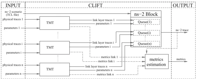
CLIFT is based on three main components, TMT, thens-2 block component and the metric estimation block. Figure1shows the different components of CLIFT and their interactions:
• TMT, the link layer component of CLIFT: for each type of link in the selected network, a physical trace is taken as input to TMT, producing a resulting link layer trace, according to the specific parameters of this link;
• ns-2 block component: we have developed a queuing module for ns-2, that inputs the resulting (from TMT) link layer traces, to schedule the transmission of the transport layer packets inns-2;
• metric estimation block: this component provides the resulting metrics (e.g.,transport layer throughput, link layer throughput efficiency, delay, etc.).
3.2
TMT and physical layer traces
In this section, we describe TMT and the format of the physical layer trace.
TMT implements the standard link layer reliability schemes such as ARQ, FEC and H-ARQ (detailed in Section3.5). The data taken as input to TMT consists of a list of parameters (characteristics of the reliability
ns−2 Block
CLIFT
OUTPUT
INPUT
Queue(1) Queue(i) Queue(n) metrics link n link layer traces nmetrics link i metrics link 1 parameters i link layer traces i
parameters 1 link layer traces 1
physical traces n parameters i physical traces i parameters 1 physical traces 1 parameters n ns−2 trace metrics estimation metrics parameters n ns−2 scenario (TCL file) TMT TMT TMT
Figure 1: Interaction between the components of CLIFT
scheme) and the physical layer trace considered. We propose two ways to use the physical layer input, depending on the origin of the erasures:
• direct use of the physical layer trace: the physical traces are measured and erasure events occur at the link layer according to real channel evolutions and to the physical layer error codes compliant to 4G requirements;
• indirect use of the physical layer trace: erasures are introduced on one error-free input trace following a Gilbert-Elliott model as explained in Section3.3.
TMT computes the equivalent output link layer trace according to the input trace and the chosen reliability scheme. We only keep data useful to our evaluations, i.e. the Link-Layer Data Units (LLDUs) (note we do not correct LLDUs or make us of retransmissions) and we modify their decoding delay according to the chosen reliability scheme. Then, we compute the throughput efficiency (i.e. goodput) and the recovery delay.
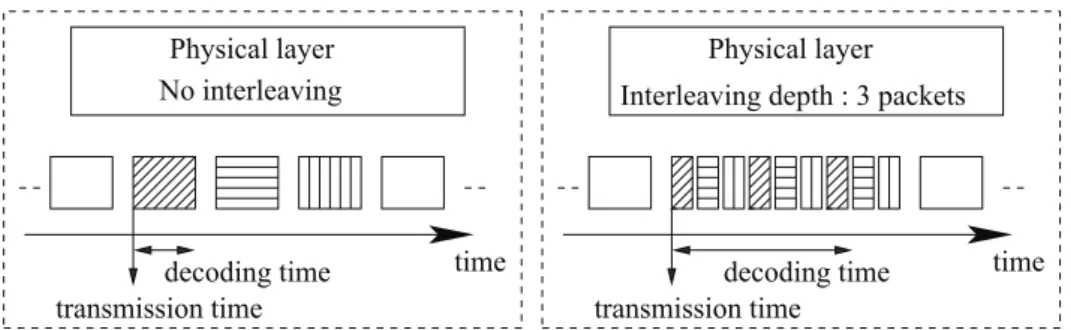
We use physical layer traces that are produced by CNES OFDM/TDM simulation softwares [38], which includes realistic satellite link characteristics, such as the type of satellite orbit, error correcting codes, etc. Each packet sent at the physical-layer level is characterized by a transmission time and a decoding time. In Figure2, in order to better assess the relationship between the transmission time and decoding time, we illustrate how they are affected by interleaving at the physical layer. We note that the transmission time is related to the bandwidth and the length of the code at the physical layer. On the other hand, the decoding time is related to the duration of the interleaving, the channel state and the transmission time. For each packet sent at the physical layer, we show a corresponding line, highlighting both the transmission time and decoding time.
We note that although we have used specific physical layer simulators, TMT can load any physical layer trace compliant with the required format, therefore it is more generally applicable to use of any traces. These may be obtained by real measurements, or from other physical layer simulators.
The decoding time is composed of the different delays introduced by the reliability schemes at the physical layer (interleaving and recovery delay). We denote:
• tias the transmission time ofLLDUi;
• dias the decoding time ofLLDUi;
Att = RT T /2 + ti+ di, the physical-layer deliversLLDUito the link layer, if there is no additional delay
(congestion, queuing, ...). Also, we consider that the LLDU is erased whendi= 0.
The principle is as follows: the decoding time of one erased LLDU is related to the reliability scheme used, in order to estimate the time when the recovered LLDU must be sent. The additional time introduced by the link layer reliability scheme, denotedd′
No interleaving
Physical layer Physical layer Interleaving depth : 3 packets
time
decoding time decoding time time transmission time transmission time
Figure 2: Physical layer traces: transmission and decoding times
the recovery ofLLDUi: d′i = tR+ dR−ti. A physical layer data unit will be delivered to the link layer at
RT T /2 + ti+ d′i.
In the following section, we derive a model of the bursty erasure link layer, and the resulting throughput efficiency and packet recovery delay. We utilize this model to validate the results derived from the TMT module. It is worth noting that TMT implements reliability schemes considering data is transmitted on all the physical layer data units of the physical layer trace. The traffic which is later scheduled on the link layer trace, generated by TMT, may not use all the available LLDUs. The metric of throughput efficiency is therefore different from the satellite link utilisation: in this section, we measure and model the throughput efficiency at the link layer level, whereas the satellite link utilization is measured at the application layer level, considering the reliability schemes and headers introduced at different layers (i.e., physical layer coding ratio, transport layer headers, etc.).
3.3
Link layer bursty erasure packet model
This section explains how we use the concept of a bursty bit error channel (physical layer) model to derive a bursty erasure packet (link layer) model. We base our analysis on the algorithms presented in [39] to model link layer reliability schemes with a slight adaptation. In [39], the authors propose two methods to express the error probabilities of an error correcting code over a bursty channel. In particular, they provide a complete expression and computation method for the bit error probability (i.e. at the physical layer). In our context, we need to modify these results by considering erasures at the link layer.
A Gilbert-Elliott channel is commonly used to represent a bursty error channel at the physical layer. The good state probability (resp. bad state) presents an error probabilityPG (resp. PB) and a changing state
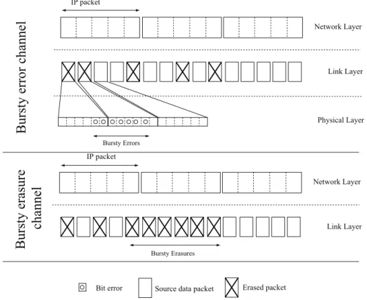
probabilityα (resp. β). In the good state (resp. bad state) errors occur with low (resp. high) probability, which illustrates the bursty aspect of the channel. We also use this model with corresponding erasure probabilities to simulate bursty erasures at the link layer as illustrated in Figure3. Note that we did not represent lost IP packets as the recovery capacity of the network layer is linked to the reliability scheme introduced. In the context of satellite transmissions, this model is of interest as long bursts of erasures might occur.
3.4
Evaluation of Erasure Probabilities
The erasure probability distribution during a transmission over a channel with memory can be analysed through a Gilbert-Elliott model. As this Gilbert-Elliott model applies to every packet, the totality of different erasure combinations over a number of packets can be considered through a mathematical induction.
We now present the iterative methods used in the following analysis. LetP (m, n), be the probability of havingm erasures over n packets, PG(m, n) (resp. PB(m, n)) the probability to have m erasures over n
packets and to be in the good state (resp. bad state) when thenth packet is received. In order to compute
P (m, n), we drive a double mathematical induction over m and n, considering first the current state of the chain, and then the current erasure probability. This solution has been proposed in [39], which contains all the details needed to obtainP (m, n).
Bit error Source data packet Erased packet IP packet Bursty Erasures Network Layer Link Layer
cha
nne
l
Burs
ty e
ra
sure
Bursty Errors IP packet Physical Layer Network Layer Link LayerBurs
ty e
rror c
ha
nne
l
Figure 3: Bursty errors and bursty erasure models
3.5
Modeling link layer reliability mechanisms with bursty erasures
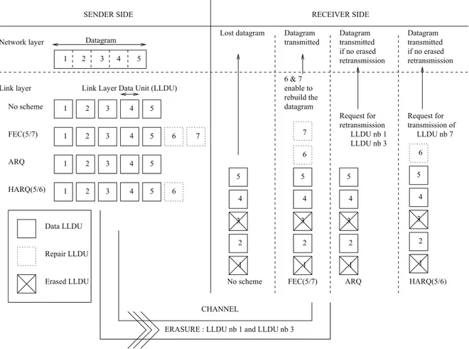
We now present the expressions for the throughput efficiency and the recovery delay for specific reliability schemes (FEC, ARQ and HARQ of type II) at the link layer. In the following, a full ’IP packet’ is fragmented into Link Layer Data Units (denoted LLDU) before transmission over the physical layer. These reliability mechanisms are presented through an example in Figure4.
In the Forward Error Correction (FEC) scheme, the sender sends a combination of data and repair LLDUs. LetND(resp. NR) be the number of data (resp. repair) LLDUs andN = ND+ NR. The process to recover
data LLDUs is successful if at leastNDLLDUs are received, otherwise (if the number of erasures is strictly
greater thanNR) no correction is possible. the FEC scheme does not enable the retransmission of LLDUs.
Automatic Repeat-reQuest (ARQ) mechanism at the link layer consists in the retransmission of the LLDUs that have been lost during the transmission.
Hybrid-ARQ (HARQ) is a combination of the FEC and ARQ mechanisms and after the first transmission of a FEC block, including data and repair LLDUs, HARQ-II allows the sender to transmit additional repair LLDUs when a recovery is not possible at the receiver side. In other words, if no correction is possible at the receiver, the transmission of additional repair LLDUs is requested by the receiver. At each new transmission, the sender transmits more LLDUs than requested by the receiver: if the receiver requiresn LLDUs to recover the data, the transmitter sends(n + NS) LLDUs when NSis the number of additional repair LLDUs sent.
In this figure, we present the LLDU sent at the link layer for the transmission of one IP packet. The reactions of the reliability schemes depends on the erasures at the link layer. The network layer capacity to recover the IP packet is linked to the reliability scheme introduced as we detail in the following sections. When there are no reliability schemes, the network layer can not rebuild the IP packet as only 4 LLDU are received and 6 are needed.
We denoteP (m, n) as the probability of having m erasure in n LLDUs. In the following expressions we consider that this probability is estimated through the model presented in Section3.4.
Data LLDU Repair LLDU Erased LLDU 2 1 3 4 5 1 2 3 4 5 1 2 3 4 5 1 2 3 4 5 1 2 3 4 5
SENDER SIDE RECEIVER SIDE
Link layer Network layer No scheme FEC(5/7) ARQ HARQ(5/6) 3 4 5 6 7 1 2 3 4 5 1 2 3 4 5 6 1 2 3 4 5 1 2 CHANNEL
ERASURE : LLDU nb 1 and LLDU nb 3 No scheme 7 6 FEC(5/7) ARQ 6 & 7 6 Datagram
Link Layer Data Unit (LLDU)
Lost datagram transmitted Datagram Datagram transmitted retransmission if no erased Request for retransmission LLDU nb 1 LLDU nb 3 datagram rebuild the enable to Datagram transmitted if no erased retransmission Request for transmission of LLDU nb 7 HARQ(5/6)
Figure 4: Error control mechanism
is designed for satellite links (with round trip times greater than 400 ms), the impact of these additional delays can be neglected in comparison to the round trip time delay.
In this article, the recovery delay computed contains the one way transmission time, for a better understand-ing on the total transmission time. Later in this article,ns-2 simulations do not consider this offset, because the one way transmission time is introduced by thens-2 link: introducing this offset would double the one way transmission time (offset added by TMT on the LLDU trace file and thens-2 link).
3.5.1 FEC: Forward Error Correction
We define the throughput efficiency for the FEC reliability scheme as the ratio of the received LLDUs and the total number of LLDUs sent:
ηF EC =
PND
i=1PR(i).i
ND+ NR
(1) wherePR(i) represents the probability that i LLDUs are received. Over a bursty erasure channel, this is
com-puted following the previously explained mathematical induction:PR(i) = P (i, ND+ NR).
If a LLDU is erased, the additional delay will correspond to the time needed to receive the whole IP packet (data and repair LLDUs) needed by the FEC scheme to evaluate whether this IP packet can be recovered. This
recovery delay,d, is related to the position of the LLDUs in the total IP packet and its expression is given in (2). d = RT T 2 + p 1 − N −1 X i=NR P (i, N − 1) ! N 2TP (2)
whereTPis the time needed to receive a LLDU andp the global erasure probability. If the LLDU is lost, we add
the time (second part of (2)) that corresponds to the time needed to receive theN LLDUs. On the average, we consider the erasure to be located in the middle of the IP packet: this explains why, if an erasure event occurs, we add N2 ×TP. Then we add this time if the LDDU can be recovered, otherwise the packet is discarded and
its recovery delay is not considered as there are no retransmissions with FEC mechanism.
3.5.2 Interleaved FEC
Interleaving is an efficient and commonly used technique to improve the data transmission over a bursty channel, as erasure bursts can be spread into a number of different codewords. It is possible to change the characteristics of the channel with (3) in order to consider the interleaving. Letp and ρ be the local erasure probability (probability for a single LLDU to be erased without considering the previous state of the channel) and the correlation between the states (considering a simplified channel withPG= 0 and PB = 1). (3) and (4)
have been proposed in [39] and we propose to utilize them to model the erasures at the link layer level. p = 1 − α
2 − α − β and ρ = α + β − 1 (3) If an interleaving with a depthI is used on this bursty channel,the authors of [39] obtain a new bursty channel with the following changing state probabilitiesαI andβI:
αI = p + ρI.(1 − p) and βI = (1 − p) + ρI.p (4)
The performance of interleaved FEC can be then obtained by applying parametersαI andβI in equations (1)
and (2).
3.5.3 ARQ: Automatic Repeat-reQuest
For this reliability scheme, The throughput efficiency (also called goodput which is, by definition, the ap-plication layer throughput) corresponds to the probability that a LLDU is received. In the context of high delay links, the channel probably changes its state before retransmissions are sent. Thus, we do not consider burst of erasures when using ARQ. Furthermore, we can neglect this notion as this scheme does not introduce correlation between different LLDUs of the same IP packets. Then, the recovery delay can be expressed as follows:
dARQ= RT T 2 + ∞ X i=1 pi−1(1 − p)i.RT T wherep is the global erasure probability.
3.5.4 HARQ-II: Hybrid ARQ of type II
Let Rr be the probability that the data can be decoded after r retransmissions, TR(r) the time needed
to receive the LLDUs of therth retransmission,N
D the number of data source LLDUs, NR the number of
repair LLDUs, andN = ND+ NR. For applications with time constraints, a limited number of authorized
The throughput efficiency for HARQ-II is expressed as the ratio of the received LLDUs and the total number of LLDUs sent: ηHARQ= PND i=1PR(i).i P∞ j=1PS(j).j
wherePR(i) is the probability that i LLDUs are received and PS(j) the probability that j LLDUs are sent. ND X i=1 PR(i).i = R−1 X z=0 Rz ! .ND+ ND−1 X i=1 PR(i).i (5)
Equation (5) represents the number of LLDUs received, which isNDifR retransmissions enabled the recovery
correction of the useful LLDU (i.e., ifPR−1
z=0 Rz, whereRzis the probability that thezthretransmission enabled
the transmission of at leastNDLLDU).Rzis derived from expressions close to (1). IfR retransmissions did
not enable the recovery; the second part of the equation determines the number of LLDUs that have successfully been received during the first transmission.
WithR = 2 (2 complementary transmissions are authorized), (5) can be calculated according to the follow-ing expression: PR(i, i < ND) = P (ND−i, ND) × NR X l1=δi,ND ,NR (ND−i)+NS−NR+l1 X l2=NS+1 l2+NS X l3=NS+1 ∆i,ND,NR,NS,l1,l2,l3 with: ∆i,ND,NR,NS,l1,l2,l3 = P (l1, NR) ×P (l2, (ND−i) + NS−NR+ l1) ×P (l3, l2+ NS) and δi,ND,NR= 0 if (ND−i) > NR (ND−i) − NRif(ND−i) < NR 1 if (ND−i) = NR
We consider every combination of erasure positions to determinePS(j). For each complementary transmission,
the number of repair LLDUs sent is linked to the current number of erasures. If there aren erasures at the first IP packet (data and repair LLDUs) sent, and if the correction capacity of the code isNR, there are two possibilities:
ifn 6 NR, no transmission of repair LLDUs is needed; ifn > NRthe receiver requests forn − NR+ NS
repair LLDUs. The expressions (6) are given withR = 2 and with P (m, n). PS(j) = NR X l0=0 δN.P (l0, N ) + N X l0=NR+1 NS X l1=0 δl0,N.P (l0, N ).P (l1, l0−NR+ NS) + N X l0=NR+1 l0+NS X l1=NS+1 δl0,l1,N.P (l0, N ).P (l1, l0−NR+ NS) (6) with:
δN = ( 1 if j = N 0 if j 6= N δl0,N = ( 1 if j = N + (l0−NR+ NS) 0 if j 6= N + (l0−NR+ NS) δl0,l1,N = ( 1 if j = N + (l0−NR+ NS) + l1 0 if j 6= N + (l0−NR+ NS) + l1
In Equation (6),PS(j) represents the number of LLDU transmitted. Each part of this equation corresponds
to one number of retransmission needed, depending on the erasure events which govern the retransmissions. If no retransmission is needed (first part) the number of LLDU transmitted isN , this event is characterized by the probabilityPS(N ). For the retransmissions, the number of LLDU transmitted is related to the number of
erasure that occurs and the parameters of HARQ. As an example,PS(N +2) is the probability to transmit N +2
LLDU: (N during the first transmission) and ((2 LLDUs transmitted on the first retransmission) or (1 LLDU transmitted on the first retransmission and1 LLDU during the second retransmission)). This is an example of the different cases that Equation (6) considers.
In order to estimate the recovery delay, we have to consider both the time needed to receive the first FEC block (data and repair LLDUs),TR(0), and the additional repair LLDUs. This recovery delay, denoted dHARQ
can be expressed as follows:
dHARQ= TR(0) + RT T 2 + ∞ X i=1 Ri.i(RT T + TR(i)) withRT T ≫ TR(i).
3.6
Cross-validation and interpretation
In this section, we measure the resulting throughput efficiency and recovery delay over link layer output. We then cross-validate the TMT tool results with the theoretical metrics presented in Section3.5.
3.6.1 Validation
For each state, we compute the theoretical metrics through the equations detailed in Section3.5and the resulting metrics obtained with TMT. In the use case presented, the physical trace corresponds to a satellite data transmission with a duration of 500 seconds and has been provided by courtesy of CNES. As the physical trace provided is error-free, we thus introduce bursty erasures over this physical layer trace following the Gilbert-Elliott model presented in Section3.3.
We present in Figure5the results obtained on a given set of parameters. The chosen parameters are:RT T = 500ms, ND−F EC = 10, NR−F EC = 12, ND−HARQ = 5, NR−HARQ = 7, α = 0.99, β ∈ [0.1; 0.98], which
induced a global erasure probabilityp ∈ [0.01; 0.3] and a length of erasure bursts tb ∈ [1; 50]. Both figures
confirm that the theoretical expressions developed fit TMT results. Note that we only present a subset of our experiments and that several other set of parameters have been tested with success.
3.6.2 Interpretation
We propose to exploit the theoretical expressions given in Section3.5to compare the three recovery mech-anisms in terms of recovery delay and throughput efficiency over a bursty channel. For the simulation, we use the following parameters: RT T = 500ms, ND = 38, NR = 13, R = 2, α = 0.98, β ∈ [0.1; 0.93], which
induces a global erasure probabilityp ∈ [0.01; 0.3] and a length of erasure bursts tb ∈[1; 14]. Please note that
0.55 0.6 0.65 0.7 0.75 0.8 0.85 0.9 0.95 1 0.2 0.3 0.4 0.5 0.6 0.7 0.8 0.9 1 T h ro u g h p u t e ff ici e n cy (% )
Probability to stay in bad state FEC(10/12) − Theory FEC(10/12) − TMT ARQ − Theory ARQ − TMT HARQ(5/7) − Theory HARQ(5/7) − TMT
(a) Validation of the throughput efficiency
0.2 0.25 0.3 0.35 0.4 0.2 0.3 0.4 0.5 0.6 0.7 0.8 0.9 1 R e co ve ry d e la y (s)
Probability to stay in bad state FEC(10/12) − Theory FEC(10/12) − TMT ARQ − Theory ARQ − TMT HARQ(5/7) − Theory HARQ(5/7) − TMT
(b) Validation of the recovery delay
Figure 5: Validation of the throughput efficiency and the recovery delay
The results presented in Figure6have been obtained with MATLAB. We note that ARQ and HARQ can transmit additional LLDUs if the IP packet cannot be rebuilt.
In the context of satellite links, the delay resulting from the retransmissions impacts the data delivery and although these retransmissions enable the recovery of lost LLDUs at a later time, they may not be gainfully utilized by the time constrained applications (VoIP, streaming ... ). When erasure occurrence is low, ARQ
0.4 0.5 0.6 0.7 0.8 0.9 1 0 0.05 0.1 0.15 0.2 0.25 T h ro u g h p u t e ff ici e n cy (% ) Erasure probability (%)
FEC ARQ HARQ
(a) Throughput efficiency
0.2 0.25 0.3 0.35 0.4 0.45 0.5 0.55 0.6 0.65 0 0.05 0.1 0.15 0.2 0.25 R e co ve ry D e la y (s) Erasure probability (%)
FEC ARQ HARQ
(b) Recovery delay
Figure 6: Throughput efficiency and recovery delay
demonstrates better performance than HARQ as the transmitter does not send useless repair LLDUs. Therefore, when erasure occurrence is higher, HARQ introduces less delay thanks to the initial repair LLDUs. Although the transmission can be reliable with both ARQ and HARQ schemes, the introduced delay needs to be considered in the design of networks with time constraints. The theoretical models presented in this paper allow a fast analysis of the performance of reliability schemes over various channels and can consequently assist the network designer with the choice of the most appropriate scheme to be used.
3.7
Discussion
In this section, we present how FEC, ARQ and HARQ-II works. We also detail the physical layer trace formats and how TMT implements the reliability schemes to produce the equivalent output of the link layer. We express the efficiency throughput and recovery delay through an analytical tool and these expressions are linked to the burst erasures that occurs in our context. Finally, we cross validate TMT and this analytical tool. We also present CLIFT, the simulation set that we use to lead realistic cross-layer studies of the impact of link layer reliability schemes on transport layer protocols performance.
4
Satellite characteristics and tested transport protocols
In the previous section, we presented how we consider the link layer reliability schemes inns-2. As a result, we propose, in this section, to detail other layers (PHY and transport) characteristics to better understand the simulation results. We present the satellite configuration and the physical layer characteristics, as the same channels and codes will be used in the following sections. We also detail the congestion control of the tested transport protocols, as their reaction to different packet events differs.
4.1
Physical layer for 4G satellite links
We consider the transmission of data between a satellite and a mobile user. The mobile user moves inside a suburban area at the speed of 60 km/h over 10 km. The satellite has a LTE waveform, transmitted in S-band with OFDM techniques. The bandwidth is 5 MHz with 300 available frequencies, the length of the FFT is 512. The satellite is in GEO orbit and has an elevation angle of40◦
.
In the rest of the article, we denote by “up-link” the link on which data are transmitted from the mobile user to the satellite, and by “down-link” the link on which data are transmitted from the satellite to the mobile user.
0.0001 0.001 0.01 0.1 1 0 5 10 15 20 25 PER Es/N0
Diffusion scenario − Down Diffusion scenario − Up Internet scenario − interleaving 36 ms Internet scenario − no interleaving ms
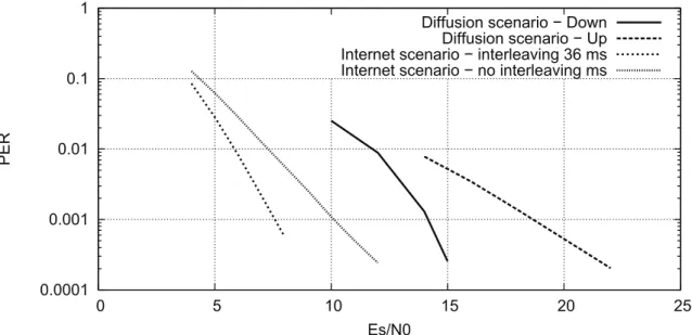
Figure 7: Performance of physical layer codes in LTE context
In Figure7, we present the performance of the physical layer codes introduced for each scenario. We can already assess the benefits provided by the interleaving at the physical layer. Figure7presents the Packet-Error-Ratio (PER) for different signal-to-noise ratio. The PER is the probability that the physical layer reliability scheme could not recover the encoded packet. We consider that the size of the LLDU is the same as the useful data that can contain one physical layer data unit: if a physical layer data unit is lost, the corresponding LLDU is lost. The link layer reliability schemes will try to recover this lost LLDU.
We consider three main scenarios, with dedicated physical layer traces:
• satellite distribution (referred to as“Distribution scenario” in the rest of this article, e.g. in Figure7): (1) on the down link, we introduce a Turbo Code 3GPP2 with a code word (before coding) of 1523 bytes; (2) on the up link, we introduce a Turbo Code 3GPP with a code word (before coding) of 33 bytes. The interleaving depth at the physical layer is 36 ms. We present the results of this scenario withEs/N 0 = 14 dB, i.e. P ER < 10−2;
• bi-directional Internet traffic with interleaving (referred to as “Interleaved Internet scenario” in the rest of this article, e.g. in Figure7): we introduce a Turbo Code 3GPP with a code word (before coding) of
33 bytes on both up and down links. The interleaving depth at the physical layer of 36 ms. We present the results of this scenario withEs/N 0 ∈ [5; 8] dB, i.e. P ER ∈ [10−2; 10−1];
• bi-directional Internet traffic without interleaving (referred to as “Non Interleaved Internet scenario” in the rest of this article, e.g. in Figure7): we introduce a Turbo Code 3GPP with a code word (before coding) of 33 bytes on both up and down links. The interleaving depth at the physical layer of 0 ms. We present the results of this scenario withEs/N 0 ∈ [5; 12] dB, i.e. P ER ∈ [10−2; 10−1].
Therefore, the differences between the scenarios are:
• “Distribution scenario” considers low bit-error rates on the physical link;
• “Interleaved Internet scenario” considers high bit-error rates on the physical link and includes the benefits of interleaving on this link;
• “Non Interleaved Internet scenario” has the same bit-error rates as the “Interleaved Internet scenario”, but has no interleaving.
As detailed in section3.2, each line of the physical layer traces corresponds to one LLDU and defined by a transmission time and a decoding time (time needed for the packet to be decoded at both physical and link layer). As the size of the physical layer unit is known, we measure that: for the Distribution scenario, the available capacity is 2.34 Mbps (up) or 2.25 Mbps (down) or and for the Internet scenario, the available bandwidth is 0.263 Mbps. The capacity is less important with the Internet scenario, we consider that the bandwidth is fairly shared between 10 users: only one line on ten available is used.
4.2
Transport layer protocols
We now detail the congestion control mechanism of diverse transport protocols. When the LLDU is being transmitted at the link layer, the reception of the SACK vector contains a hole and the transmitter believes the packet is lost. Also, an ARQ mechanism can introduce an important number of spurious retransmissions as the non-acknowledgement of some IP packets in the SACK vector greatly deteriorate the performance, even if the “lost” IP packets are under retransmissions at the link layer. With HARQ-II, the preliminary transmission of a FEC block prevents the congestion window from decreasing (there are no lost IP packets in the SACK vector), but exploits useful bandwidth. As a result, a trade-off has to be found between reducing the congestion window (with ARQ) and reducing the available bandwidth (with HARQ-II).
TCP New Reno is a protocol widely deployed which can be considered as a reference in the world of trans-port protocols. Indeed it enables a reliable transmission and is loss-based: this means that the evolution of its congestion window is strongly ruled to acknowledgement rhythm. When a local error occurs (non acknowledge-ment of IP packeti and acknowledgement of IP packet i + 1, for instance) the congestion window is halved. In the context of high BDP path, where the optimal congestion window is high, these reductions have a bad effect on the end-to-end communication.
We propose to compare the performance of:
• TCP Westwood+ [10], which reduce the congestion window to an optimal value calculated depending on an estimation of the available bandwidth;
• TCP Hybla [8], which has been designed especially for satellite links; • CUBIC [7], which is implemented in GNU/Linux and Android systems; • TCP Compound [9], which is implemented in Windows systems.
It is worth noting that TCP Compound and CUBIC are good candidate for high BDP paths.
We enabled the “SACK” option inns-2 for each simulation because it is a very common loss recovery mechanism at the transport layer level.
5
Distribution scenario
In this section, we propose to exploit the physical layer trace of the distribution scenario to assess the impact of ARQ and HARQ-II on the performance of various transport layer protocols.
5.1
One FTP transmission
We consider one FTP transmission between the mobile receiver and the satellite gateway. When the direction of the transmission is up, the mobile transmits data; when the direction of the transmission is down, the mobile receives data. The size of the IP packets is 1500 bytes. In this scenario, we haveEs/N 0 = 14 dB which corresponds to a physical layer unit error ratio slightly lower than10−2.
In Figure8, we present the average throughput achieved by the different transport protocols using different reliability schemes, when the mobile unit transmits data to a server.
0 0.5 1 1.5 2 2.5
TCP NewReno CUBIC TCP Compound TCP Hybla TCP Westwood
T h ro u g h p u t [Mb p s]
ARQ HARQ10/12 HARQ10/15 HARQ50/52
Figure 8: Throughput of different versions of TCP depending on link layer retransmission schemes (UP)
Firstly, when TCP New Reno or TCP Compound are enabled at the transport layer, the throughput is lower than with other protocols. Also, we measure that for both TCP New Reno and TCP Compound, ARQ at the link layer overcomes HARQ-II in terms of achievable goodput.
Secondly, we observe that TCP Hybla, CUBIC, and TCP Westwood reaches the capacity of the satellite link with ARQ scheme at the link layer. As a result, we measure that when HARQ(X/Y) is used at the link layer, the used bandwidth is multiplied by XY. Indeed, congestion control of these protocols overcome the problems introduced by local errors at the transport layer, as they have been designed without link layer considerations. TCP Hybla has an important increase rate of the congestion window. CUBIC decreases its congestion window by multiplying it by 0.8. TCP Westwood reduces the congestion window to a value computed with an estimation of the optimal window.
To further illustrate the performance, we present in Table1the characteristics of the retransmissions at the transport layer when the transport layer protocol is CUBIC: we highlight that introducing HARQ-II at the link layer enable to reduce the number of transport layer retransmissions.
When the mobile receives data, the physical code word is much longer. As a result, based on the results presented in Figure8, we can already assess that considering important coding ratio for HARQ-II would have a negative impact on the throughput achievable by transport layer protocols. In Figure9, we confirm that the trends observed previously can be confirmed in this scenario context.
As TCP Westwood, CUBIC and TCP Hybla has the best performance in terms of throughput, and as the delay measured for TCP Westwood and CUBIC are the same, we propose to observe the evolution of these
Table 1: Distribution scenario: transport layer retransmissions with CUBIC Link layer Retransmission Maximum number
scheme probability of retransmission
ARQ 0.0222 5 HARQ(10/12) 0.00769 4 HARQ(10/15) 0.00136 2 HARQ(50/52) 0.0204 5 0 0.5 1 1.5 2 2.5
TCP NewReno CUBIC TCP Compound TCP Hybla TCP Westwood
T h ro u g h p u t [Mb p s] ARQ HARQ10/12
Figure 9: Throughput of different versions of TCP depending on link layer retransmission schemes (DOWN)
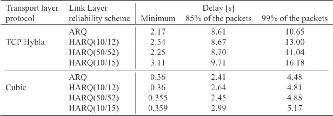
delays for CUBIC and TCP Hybla in Table2. We plot the minimum measured delay, the delay needed to acknowledge 85% of the IP packets and the delay needed to acknowledge 99% of the IP packets. Contrary to what one might think, we observe that when HARQ-II is introduced, the delay is more important. Indeed, an IP packet (1500 bytes) is distributed among 47 LLDUs (33 bytes) and when ARQ is involved, the minimum time needed to transmit an IP packet is the time needed to transmit 47 LLDUs. As an example, when HARQ(10/12) is chosen, the minimum time needed to transmit an IP packet is the time needed to transmit 60 LLDUs. Also, we note a difference between the delay measured when TCP Hybla or CUBIC are introduced: the important delay introduced by TCP Hybla can be explained the fact that its congestion window oscillates between 750 and 200 packets where the optimal congestion window (estimated by:RT T ∗ bandwidth/P ktSize) is 93 packets.
5.2
Discussion
We have presented, in a specific scenario, the problem of reducing more often the congestion window in case of local errors with ARQ at the link layer and reducing the available bandwidth with HARQ-II. Also, when we consider a FTP application and a physical layer unit error ratio is lower than10−2, TCP New Reno and
TCP Compound do not achieve in using the whole available bandwidth. TCP Westwood, CUBIC and TCP Hybla succeed in optimizing the use of the bandwidth, as they were designed without link layer considerations and to overcome local errors problems. We illustrate that HARQ-II only exploits useful bandwidth when they are involved at the transport layer. Also, the delay introduced by TCP Hybla is more important than the delay introduced by TCP Westwood and CUBIC. Based on these statements, we believe that the best combination we present would be to use CUBIC, TCP Westwood or TCP Hybla with ARQ at the link layer, when the physical
Table 2: Average delay of IP packets (UP) Transport layer Link Layer Delay [s]
protocol reliability scheme Minimum 85% of the packets 99% of the packets
ARQ 2.17 8.61 10.65 TCP Hybla HARQ(10/12) 2.54 8.67 13.00 HARQ(50/52) 2.25 8.70 11.04 HARQ(10/15) 3.11 9.71 16.18 ARQ 0.36 2.41 4.48 Cubic HARQ(10/12) 0.36 2.64 4.81 HARQ(50/52) 0.355 2.45 4.88 HARQ(10/15) 0.359 2.99 5.17
layer unit error is under10−2.
6
Interleaved Internet scenario
In this section, we evaluate the impact of retransmission schemes on the performance of the transport protocols performance, in the Internet scenario detailed in section4.1. The difference with the previous section is that the physical layer errors are more prevalent, and less capacity is available for each transmission. Our aim is to verify the validity of the assumptions made in the previous section are still valuable when the number of error increases.
We consider one FTP transmission of IP packets of1500 bytes. The bandwidth is limited to 263 kbps, as we consider that the bandwidth is fairly shared between 10 users. We compare the performance of the different transport protocols with diverse retransmission schemes and when there is a physical layer interleaving of36 ms. The main difference with the results presented in the previous section is that we consider high physical layer unit error rate. In Figure10, we present the average throughput measured at the mobile receiver side.
TCP Hybla shows very good performance, whatever the value ofEs/N 0 is. We explain this by the fact that TCP Hybla blasts packets, overestimates the optimal bandwidth achievable and the congestion window of this transport protocol is very important. As a result, this protocol could be a good candidate to transmit data over 4G links.
If we consider the performance of other tested transport protocols, when the physical layer unit error rate is high (higher than10−2, Figure7), we note that there are important benefits in terms of bandwidth that can be
achieved when HARQ-II are introduced at the link layer. As an example, we focus at the results measured when CUBIC is introduced at the transport layer. AtEs/N 0 = 5 dB, with ARQ, we measured an achieved throughput of81 kbps, and with HARQ(10/12), of 140 kbps: introducing HARQ(10/12) at the link layer increases the goodput by59 kbps. At Es/N 0 = 6 dB, with ARQ, we measure an achieved throughput of 153 kbps, and with HARQ(10/12), of215 kbps: introducing HARQ(10/12) increases the goodput by 62 kbps.
When there are less physical layer errors, we validate the assumption that when the capacity is fully ex-ploited, transmitting redundancy packets with HARQ-II reduces the goodput, i.e. the available bandwidth. Indeed, when the transport layer protocol is Cubic, atEs/N 0 = 8 dB, with ARQ, we measure an achieved throughput of258 kbps, and with HARQ(10/12), of 215 kbps. Introducing HARQ(10/12) reduces the goodput by43 kbps.
We propose to evaluate the behavior observed in the previous simulations by considering the transmission of 0.1 Mb (median Internet web page size12,13) with different transport layer protocols, different reliability schemes
and different transmission times (to consider different channel states). In Table3, we present the time needed to transmit these data using the different simulation parameters: we ran200 iterations and present the average value. As pointed out before, the impact of the value ofEs/N 0 severely impacts on the transmission delay. If
12According to Google Web Metrics, the median Internet web page size is 180 kb. More than 30 % of the web pages weight less than 100kb.
100 150 200 250 5 6 7 8 T h ro u g h p u t [Kb p s] Es/N0 [dB]
ARQ HARQ10/12 HARQ50/52
(a) TCP New Reno
100 150 200 250 5 6 7 8 T h ro u g h p u t [Kb p s] Es/N0 [dB]
ARQ HARQ10/12 HARQ50/52
(b) TCP Compound 100 150 200 250 5 6 7 8 T h ro u g h p u t [Kb p s] Es/N0 [dB]
ARQ HARQ10/12 HARQ50/52
(c) TCP Westwood 100 150 200 250 5 6 7 T h ro u g h p u t [Kb p s] Es/N0 [dB]
ARQ HARQ10/12 HARQ50/52
(d) TCP Hybla 100 150 200 250 5 6 7 8 T h ro u g h p u t [Kb p s] Es/N0 [dB]
ARQ HARQ10/12 HARQ50/52
(e) Cubic
Figure 10: Transport layer performance: impact of HARQ-II and ARQ whenEs/N 0 decrease
the transport protocol is not TCP Hybla and if the signal-to-noise ratio is low, we measure the benefits in terms of delay provided by the initial transmission of a FEC block with HARQ-II. We also validate the fact that these benefits are limited whenEs/N 0 increases, and ARQ has better performance.
In this section, we conclude that when the number of error increases at the physical layer, HARQ-II enables a significant improvement of the performance of transport layer protocols: we justify this by measuring the achievable throughput when FTP applications are considered and by measuring the delay needed to transmit a fixed amount of data.
7
Non Interleaved Internet Scenario
In this section, we consider a scenario with no interleaving at the physical layer: the mobile user transmits data (FTP applications), with Cubic or TCP Hybla at the transport layer, with different retransmission schemes at the link layer.
In Figure11, we present the achievable throughput. The results will be compared to those presented in Figure10, with interleaving at the physical layer of36 ms duration.
We can observe that the interleaving has no effect on TCP Hybla performance. Indeed, this results follows from the property of TCP Hybla that transmits IP packets by setting its congestion window at an estimated
Table 3: Time needed to transmit0.1 Mb Transport layer Link Layer Es/N0
protocol reliability scheme 5 dB 6 dB 7 dB 8 dB ARQ 12.1 8.1 5.6 5.0 TCP New Reno HARQ(10/12) 8.2 5.7 5.2 5.1 HARQ(10/15) 6.5 5.9 5.9 5.9 ARQ 12.0 8.2 5.7 4.9 TCP Compound HARQ(10/12) 8.5 5.8 5.2 5.1 HARQ(10/15) 6.5 5.9 5.9 5.9 ARQ 12.3 8.3 5.6 4.9 TCP Westwood HARQ(10/12) 8.6 5.7 5.2 5.1 HARQ(10/15) 6.5 5.9 5.9 5.9 ARQ 5.4 4.6 4.2 4.0 TCP Hybla HARQ(10/12) 5.3 4.8 4.6 4.6 HARQ(10/15) 5.8 5.5 5.5 5.5 ARQ 9.8 7.1 5.4 4.8 Cubic HARQ(10/12) 7.3 5.4 5.2 5.1 HARQ(10/15) 6.2 5.9 5.9 5.9 100 150 200 250 5 6 7 8 9 T h ro u g h p u t [Kb p s] Es/N0 [dB]
ARQ HARQ10/12 HARQ50/52
(a) TCP Hybla 100 150 200 250 5 6 7 8 9 10 11 12 T h ro u g h p u t [Kb p s] Es/N0 [dB]
ARQ HARQ10/12 HARQ50/52
(b) Cubic
Figure 11: Transport layer performance, without physical layer interleaving
congestion window.
With Cubic, when ARQ is introduced at the link layer, with interleaving, atEs/N 0 = 8 dB the achieved throughput is258 kbps ; without interleaving, at Es/N 0 = 8 dB the achieved throughput is 111 kbps, and at Es/N 0 = 12 dB the achieved throughput is 258 kbps. In this case, at equivalent Es/N 0 level, interleaving enables a gain of147 kpbs ; to achieve the same throughput, interleaving enables a gain of 4 dB in Es/N 0.
With Cubic, when HARQ(10/12) is introduced at the link layer, with interleaving, atEs/N 0 = 6 dB the achieved throughput is215 kbps ; without interleaving, at Es/N 0 = 6 dB the achieved throughput is 106 kbps, and at Es/N 0 = 8 dB the achieved throughput is 215 kbps. In this case, for an equivalent Es/N 0 level, interleaving enables a gain of109 kpbs ; to achieve the same throughput, interleaving enables a gain of 2 dB in Es/N 0.
8
Conclusion
In this article, we present a study over the impact of link layer reliability schemes on the performance of transport layer protocols. We present a simulation setup that exploits realistic physical layer traces comprising: Trace Manager Tool (TMT) computes the output of the link layer by implementing reliability schemes on them,
and Cross-Layer InFormation Tool (CLIFT) enablesns-2 to read these traces. We note that an interface module similar to that developed forns-2 would be required in order to integrate TMT with other simulators, like e.g. ns-3.
When redundancy data is transmitted (with use of error correction codes), we show that there are less congestion window reductions, and an improved use of bandwidth for data transmission on a satellite link. However, if the channel capacity is reached (e.g., for an efficient transport layer protocol that is operating with a low physical layer bit-error rate), transmitting the redundancy data is counter productive; on the other hand, if the number of bit-errors is high (resulting in erasure events at the link layer), we show that HARQ-II can outperform ARQ at the link layer. In conditions where the physical channel error rate is high, Hybrid-ARQ results in the best performance for all TCP variants considered, with up to 22% improvements compared to other schemes.
References
[1] Cheffena M, Perez-Fontan F. Channel Simulator for Land Mobile Satellite Channel Along Roadside Trees.
IEEE Transactions on Antennas and Propagation 2011; 59:1699–1706, doi:10.1109/TAP.2011.2122297.
[2] Celandroni N, Gotta A. Performance Analysis of Systematic Upper Layer FEC Codes and Interleaving in Land Mobile Satellite Channels. IEEE Transactions on Vehicular Technology 2011; 60:1887–1894, doi:10.1109/TVT.2011.2122253.
[3] Lin S, Costello DJ. Error control coding: fundamentals and applications, vol. Chapter 15. Ed. Prentice-Hall, 1983.
[4] Berlekamp E, Peile R, Pope S. The application of error control to communications. Communications
Magazine, IEEE april 1987; 25(4):44 –57, doi:10.1109/MCOM.1987.1093590.
[5] Ewald N, Kemp A. Performance analysis of link-layer hybrid arq with finite buffer size. Personal, Indoor
and Mobile Radio Communications, 2008. PIMRC 2008. IEEE 19th International Symposium on, 2008; 1
–5, doi:10.1109/PIMRC.2008.4699575.
[6] Larmo A, Lindstrom M, Meyer M, Pelletier G, Torsner J, Wiemann H. The LTE link-layer design.
Com-munications Magazine, IEEE april 2009; 47(4):52 –59, doi:10.1109/MCOM.2009.4907407.
[7] Ha S, Rhee I, Xu L. Cubic: a new tcp-friendly high-speed tcp variant. SIGOPS
Oper. Syst. Rev. Jul 2008; 42(5):64–74, doi:10.1145/1400097.1400105. URL
http://doi.acm.org/10.1145/1400097.1400105.
[8] Caini C, Firrincieli R. Tcp hybla: a tcp enhancement for heterogeneous networks. International journal of
satellite communications and networking 2004; 22.
[9] Tan K, Song J, Zhang Q, Sridharan M. Compound TCP: A Scalable and TCP-Friendly Congestion Control for High-speed Networks. 4th International Workshop on Protocols for Fast Long-Distance Networks
(PFLDNet), 2006. URLhttp://www.hpcc.jp/pfldnet2006/paper/s4_01.pdf.
[10] Mascolo S, Casetti C, Gerla M, Sanadidi MY, Wang R. Tcp westwood: Bandwidth estimation for enhanced transport over wireless links. Proceedings of the 7th annual international conference on Mobile computing
and networking, MobiCom ’01, ACM: New York, NY, USA, 2001; 287–297, doi:10.1145/381677.381704.
URLhttp://doi.acm.org/10.1145/381677.381704.
[11] Allman M, Paxson V, Blanton E. TCP congestion control. RFC 5681, RFC Editor, Fremont, CA, USA Sep 2009. URLhttp://www.rfc-editor.org/rfc/rfc5681.txt.
[12] global standard for international mobile telecommunications “IMT-Advanced” I. Circular letter. ITU-R 2008; .
[14] LTE-Advanced I. pg. 6 July 2011; .
[15] Nakamura T, Abeta S, Iwamura M, Abe T, Tanno M. Overview of lte-advanced and standardization trends.
NTT DOCOMO Technical Journal 2011; Vol. 12.
[16] Akyildiz IF, Gutierrez-Estevez DM, Reyes EC. The evolution to 4G cellular systems: LTE-Advanced. Physical Communication Aug 2010; doi:10.1016/j.phycom.2010.08.001. URL
http://dx.doi.org/10.1016/j.phycom.2010.08.001.
[17] Kotuliakov K, imlatkov D, Polec J. Analysis of arq schemes. Telecommunication Systems 2011; :1–6doi: 10.1007/s11235-011-9659-1. URLhttp://dx.doi.org/10.1007/s11235-011-9659-1. [18] Badia L, Levorato M, Zorzi M. Markov analysis of selective repeat type ii hybrid arq using block codes.
Communications, IEEE Transactions on september 2008; 56(9):1434 –1441, doi:10.1109/TCOMM.2008.
060374.
[19] Wang R, Taleb T, Jamalipour A, Sun B. Protocols for reliable data transport in space internet.
Communi-cations Surveys Tutorials, IEEE quarter 2009; 11(2):21 –32, doi:10.1109/SURV.2009.090203.
[20] Mittag J, Papanastasiou S, Hartenstein H, Strom E. Enabling accurate cross-layer phy/mac/net simulation studies of vehicular communication networks. Proceedings of the IEEE july 2011; 99(7):1311 –1326, doi:10.1109/JPROC.2010.2103291.
[21] Alfredsson S, Brunstrom A, Sternad M. Transport protocol performance over 4g links: Emulation method-ology and results. in Proceedings of ISWCS06, 2006.
[22] Chiasserini CF, Meo M. A reconfigurable protocol setting to improve tcp over wireless. Vehicular
Tech-nology, IEEE Transactions on nov 2002; 51(6):1608 – 1620, doi:10.1109/TVT.2002.804863.
[23] Celandroni N, Ferro E, Giambene G, Marandola M. Sat01-3: Tcp performance in a hybrid satellite network by using acm and arq. Global Telecommunications Conference, 2006. GLOBECOM ’06. IEEE, 2006; 1 –6, doi:10.1109/GLOCOM.2006.472.
[24] Chockalingam A, Zorzi M, Tralli V. Wireless tcp performance with link layer fec/arq. Communications,
1999. ICC ’99. 1999 IEEE International Conference on, vol. 2, 1999; 1212 –1216 vol.2, doi:10.1109/ICC.
1999.765503.
[25] Liu C, Modiano E. On the performance of additive increase multiplicative decrease (aimd) protocols in hybrid space-terrestrial networks. Comput. Netw. ISDN Syst. Apr 2005; 47(5):661–678, doi:10.1016/j. comnet.2004.08.002. URLhttp://dx.doi.org/10.1016/j.comnet.2004.08.002.
[26] Barakat C, Al Fawal A. Analysis Of Link-Level Hybrid FEC/ARQ-SR For Wireless Links and Long-Lived TCP traffic. Rapport de recherche RR-4752, INRIA 2003. URL
http://hal.inria.fr/inria-00071835.
[27] Sorour S, Valaee S. A network coded arq protocol for broadcast streaming over hybrid satellite systems.
Personal, Indoor and Mobile Radio Communications, 2009 IEEE 20th International Symposium on, 2009;
1098 –1102, doi:10.1109/PIMRC.2009.5449889.
[28] Dukkipati N, Mathis M, Cheng Y, Ghobadi M. Proportional rate reduction for tcp. Proceedings of the 11th
ACM SIGCOMM Conference on Internet Measurement 2011, Berlin, Germany - November 2-4, 2011,
2011. URLhttp://conferences.sigcomm.org/imc/2011/program.htm.
[29] Jung H, gyu Kim S, Yeom H, Kang S, Libman L. Adaptive delay-based congestion control for high bandwidth-delay product networks. INFOCOM, 2011 Proceedings IEEE, 2011; 2885 –2893, doi:10.1109/ INFCOM.2011.5935127.
[30] Dukkipati N, Refice T, Cheng Y, Chu J, Herbert T, Agarwal A, Jain A, Sutin N. An argument for increasing TCP’s initial congestion window. SIGCOMM Comput. Commun. Rev. Jun 2010; 40(3):26–33, doi:10.1145/ 1823844.1823848. URLhttp://doi.acm.org/10.1145/1823844.1823848.