OATAO is an open access repository that collects the work of Toulouse
researchers and makes it freely available over the web where possible
Any correspondence concerning this service should be sent
to the repository administrator:
[email protected]
This is an author’s version published in:
http://oatao.univ-toulouse.fr/24486
To cite this version:
Zhang, Chuanfang John and Park, Sang-Hoon and Ronan, Oskar and Harvey,
Andrew and Seral-Ascaso, Andrés and Lin, Zifeng
and McEvoy, Niall and
Boland, Conor S. and Berner, Nina C. and Duesberg, Georg S. and Rozier,
Patrick
and Coleman, Jonathan N. and Nicolosi, Valeria Enabling Flexible
Heterostructures for Li-Ion Battery Anodes Based on Nanotube and
Liquid-Phase Exfoliated 2D Gallium Chalcogenide Nanosheet Colloidal Solutions.
(2017) Small, 13 (34). 1701677. ISSN 1613-6810
Enabling Flexible Heterostructures for Li-Ion Battery
Anodes Based on Nanotube and Liquid-Phase Exfoliated
2D Gallium Chalcogenide Nanosheet Colloidal Solutions
Chuanfang Oohn) Zhang,
*
Sang-Hoon Park, Oskar Ronan, Andrew Harvey,
Andrés Seral-Ascaso, Zifeng Lin, Niall McEvoy, Conor S. Bo/and, Nina
C.
Berner,
Georg S. Duesberg, Patrick Rozier, Jonathan N. Coleman,* and Valeria Nicolosi*
2D metal chalcogenide (MC) nanosheets (NS) have displayed high capacities as
lithium-ion battery (LiB) anodes. Nevertheless, their complicated synthesis routes
coupled with low electronic conductivity greatly limit them as promising LiB electrode
material. Here, this work reports a facile single-walled carbon nanotube (SWCNT)
percolating strategy for efficiently maximizing the electrochemical performances of
gallium chalcogenide (GaX, X= S or Se). Multiscaled flexible GaX NS/SWCNT
heterostructures with abundant voids for Li
+diffusion are fabricated by embedding
the liquid-exfoliated GaX NS matrix within a SWCNT-percolated network; the latter
improves the electron transport and ion diffusion kinetics as well as maintains the
mechanical flexibility. Consequently, high capacities (i.e., 838 mAh g-1 per gallium
(II) sulfide (GaS) NS/SWCNT mass and 1107 mAh g-1 per GaS mass; the latter is
close to the theoretical value) and good rate capabilities are achieved, which can be
majorly attributed to the alloying processes of disordered Ga formed after the first
irreversible GaX conversion reaction, as monitored by in situ X-ray diffraction. The
presented approach, colloidal solution processing of SWCNT and liquid-exfoliated
MC NS to produce flexible paper-based electrode, could be generalized for wearable
energy storage devices with promising performances.
Dr. C. F. Oohn) Zhang, Dr. S.-H. Park, A. Harvey, Dr. A. Seral-Ascaso, Dr. N. McEvoy, Dr. C. S. Boland, Dr. N. C. Berner, Prof. G. S. Duesberg, Prof. J. N. Coleman, Prof. V. Nicolosi
Centre for Research on Adaptive Nanostructures and Nanodevices (CRANN) and Advanced Materials Bio-Engineering
Research Centre (AMBER) Trinity College Dublin Dublin 2, lreland
E-mail: [email protected]; [email protected]; [email protected]
Dr. C. F. Oohn) Zhang, Dr. S.-H. Park, Dr. A. Seral-Ascaso, Dr. N. McEvoy, Dr. N. C. Berner, Prof. G. S. Duesberg, Prof. V. Nicolosi
School of Chemistry Trinity College Dublin Dublin 2, lreland
DOi: 10.1002/smll.201701677
O. Ronan, A. Harvey, Dr. A. Seral-Ascaso, Dr. C. S. Boland, Prof. J. N. Coleman School of Physics
Trinity College Dublin Dublin 2, lreland Dr. Z. lin, Dr. P. Rozier CIRIMAT
Université de Toulouse
CNRS, INPT, UPS, 118, route de Narbonne 31062 Toulouse Cedex 9, France
1.
Introduction
The incredible popularity of portable consumer electronics
bas greatly stimulated the development of safe, high-energy/
power density, long cycle-life energy storage devices,
(1-41 espe
cially lithium-ion batteries (LiBs).l5l Commercial graphite
anodes suffer from relatively low theoretical capacity
(=372 mAh g -1) and sluggish ion kinetics (10-
11-10-10 cm
2s-1 )
(61
upon Li
+intercalation/de-intercalationVl Engineering the
electrode by nanostructuring
(S-lO] or designing porous low
dimensional materials[11-
141 may result in faster Li
+diffu
sion and thus improve their rate capability.
[15•17-
201 Recently,
2D nanomaterials have attracted huge research attention
for their use in LiBs due to their exotic properties.l
21-
231 As
a typical example, the layered metal chalcogenides (MCs)
including III-VI/IV-VI layered semiconductors (e.g., GaS,
GaSe, InSe, and SnS
2) and transition metal dichalcogenides
(e.g., MoS
2,WS
2, and ReS
2) possess higher specific capacities
(>550 mAh g-1)
(24,251 and larger interlayer spacing comparedto graphite,
(26-3°1 allowing a rapid Li
+insertion/extraction
process without inducing significant volume changes. More
over, the weak van der Waals forces among the MC sheets
facilitate the production of nanosheet (NS) dispersions
via a facile exfoliation strategy.l31-331 To date, molybdenum
disulfide (MoS
i) bas been the most widely investigated lay
ered MC for use as anodes in both LiB[
34.3
5l and sodium-ion
batteries.l361 Others, such as tungsten disulfide (WS
2)[5l and
rhenium disulfide (ReS
2),
[26•
371 have recently been reported
as having good electrochemical performances. Undoubtedly,
the layered MC family is thus far relatively unexplored but
shows remarkable potential for LiBs. Nevertheless, their poor
electrical conductivity severely limits the electron transport
and leads to a series of issues, such as low measured capaci
ties, rapid capacity decay, and thus poor rate capability.
(38,391
Incorporating the MC NS into a conductive scaffold such
as graphene,
(401 carbon nanotubes,(411 or conducting poly
mers,(
421 for instance, could effectively main tain the structural
integrity of the electrode while exposing more active sites to
the electrolyte, resulting in much higher capacities as well as
better rate capability.
As a representative member of layered MC family,
gallium (II) sulfide (GaS) possesses an indirect bandgap
of 2.5 eV and is of interest for many applications ranging
from photoelectronics[
431 to gas sensing.l
441 However, a few
studies have been conducted on GaS as an LiB anode mate
rial, apart from that of Meng et al., who deposited GaS
xthin
films of quite low mass onto single-walled carbon nanotubes
(SWCNTs) via atomic layer deposition, yielding a prom
ising discharge capacity of 575 mAh g-1 (per total composite
mass) and 770 mAh g-1 (per mass of GaSx) at 120 mA g-1.(
241
However, this synthesis process is not scalable and can
potentially give rise to the hazardous H
2S leakage in the
temperature range used (150-200 °C). We believe for such
materials to be competitive in LiB, a simple, scalable and
environmentally friendly production of MC NS would be
necessary.l301 To this end, liquid-phase exfoliation (LPE) bas
been widely recognized as an efficient, scalable and low
cost approach to obtain the 2D NS dispersions in suitable
solvents.l3
3•
45•461
Herein, a facile SWCNT percolating strategy for effi
ciently maximizing the electrochemical performances of gal
lium chalcogenide (GaX, X= S or Se) is reported. Through
environmentally friendly solution processing of SWCNT and
liquid-phase exfoliated GaX NS, we obtained freestanding,
flexible GaX NS/SWCNT heterostructures with NS matrix
well embedded in the SWCNT-percolated network. Such
a hierarchical nanostructure enables high capacities and
fast rate capabilities in the GaX NS/SWCNT paper com
posite, holding great promise for practical LiB applications.
The charge storage mechanism was studied by in situ X-ray
diffraction. The superior electrochemical Li
+-storage per
formances could be ascribed to the advantages associated
with the multiscaled hierarchical nanostructure at the same
time: (i) the open channels might result in faster Li
+diffu
sion. (ii) The entangled SWCNT network forms developed,
percolated electron transport paths, lowering the junction
resistance. (iii) SWCNT could function as a "conductive
binder," maintaining the structural integrity of the thick elec
trode without losing electrical contact with the current col
lector.l47•481 Moreover, the absence of an insulating binder
leads to dead-volume free electrode, allowing the composite
to perform to its full potential. We believe the approach for
the preparation of MC NS flexible conductive composites can
be generalized, with the porous scaffold ranging from gra
phene to SWCNT, etc., while the NS could range from GaTe,
InS, InSe, InTe, to other, yet untested, MC NS. The resultant
composite films could find applications in wearable elec
tronics and optoelectronics, energy-storage systems, or sen
sors, to name but a few.
2.
Results and Discussion
In general, successful exfoliation of 2D materials is achieved
when the energy cost of mixing with the solvent is mini
mized. This tends to occur for solvents with similar surface
energy to the 2D material to be exfoliated.(33,
45] In a pre
vious report, we found that GaS could be well exfoliated in
isopropanol (IPA);
(331 therefore, in this work we similarly
bath-sonicated the commercial GaS and GaSe powders,
(491
utilizing the sonic energy to overcome the weak van der
Waals coupling of the layers and forming an NS-enriched dis
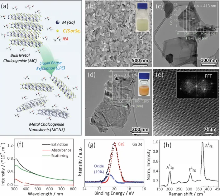
persion. This is schematically illustrated in Figure la.
Scan
ning and transmission electron microscopy (SEM and TEM,
respectively) of the obtained dispersions show large quanti
ties of exfoliated NS with well-defined edges and no apparent
damage in the basal planes, which confirms the good quality
of the exfoliated material (Figure lb-e).l
501 Statistical anal
ysis of the TEM images determines that the GaS NS have
(L) = 413 ± 26 nm (the inset of Figure le), in good agreement
with (L) = 410 nm derived from the measured extinction
and absorption spectra, as well as the subtracted scattering
spectra (Figure lf)_(5o,5i] Using previously determined met
ries from the extinction spectra the GaS NS concentration is
found to be 2 mg mL-1.
(50,511
As for the GaSe, the as-prepared solution exhibits an
orange color (the inset of Figure ld). The TEM in Figure ld
indicates the curved morphology of the GaSe NS with mean
(a) .
·
·
.
. .
.
.
BulkMetal
Chalcogenide (MC)
Liquid Phase
Exfoliation (LPE)
.
'
·
.
..
.
..
..
..
...:
...:
..
,:::i;/j:_�\:
..
,·�
.
:
�
.
·
·
.
.
'·
..
,�•... � r /,• . ••• •• . --· .. ... .. ;f.�t
;
•,.. ·�
..
�..
..
-.... . : �;
....
·
..
�
Meta/ Chalcogenide
Nanosheets(MC NS)
�-1.2
(f)
E
-- Extinction
--
A
bsorbance
(g)
!\
Gas
JI
\
Ga 3d
1.0
è
0.8
ïii
(h)
--
Scattering
1'
� 0.8
�
-
-� 0.4
r
t
Oxide
.
jJ
.
\
3
.s
0.6
E 0.4
0
V> C o.,.S
0
.
0
{..__
...:::.:::::::========l
(19%)f
•
Z 0.2
300
400 500 600 700
Wavelength / nm
800
24
Binding Energy / eV
22
20
18
16
150 200 250 300 350 400 450
Raman shift / cm
•l
Figure 1. a) Schematic of MC NS production through a liquid-phase exfoliation approach. b) SEM and c) TEM of exfoliated Gas NS. lnset in part
(c) is the Gas NS size distribution. d) TEM and e) high-resolution TEM of exfoliated GaSe NS. lnsets in parts (d) and (e) are the size distribution
and fast Fourier transform pattern of exfoliated GaSe NS, respectively, showing a highly crystalline structure. O Optical extinction, absorbance, and
scattering spect
r
a of a typical Gas NS dispersion. Here, intensity represents Extinction, Absorbance, or Scattering as appropriate. g) Ga 3d XPS
and h) Raman spectrum of exfoliated Gas NS.
flake size of 338 ± 38 nm (Figure ld and its inset). The high
resolution TEM and its corresponding fast Fourier transform
pattern are shown in Figure le and its inset, respectively,
showing the highly crystalline structure of the exfoliated
GaSeNS.
To investigate if defects were introduced to the GaS NS
during sonication, both X-ray photoelectron spectroscopy
(XPS) and Raman spectroscopy were performed. The decon
voluted XPS of the Ga 3d core level (Figure lg) shows that
the GaS NS exhibits only a small amount of degradation
from a GaxOy component which can be found at a slightly
higher binding energy than the dominant GaS species. The
characteristic lattice vibrations at 195, 301, and 370 cm-1
corresponding to the GaS A\
8,E
128,and the A
128modes,
respectively, are found in the Raman spectrum displayed in
Figure lh.
l
43.s
21
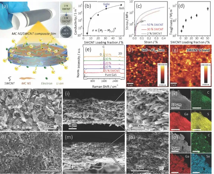
Next, binder-free flexible composite electrodes were pre
pared, assisted by a vacuum filtration of the mixture of MC
NS/SWCNT dispersions, as shown in Figure 2a. As references,
pure MC NS and SWCNT films were similarly produced. A
typical TEM image of SWCNT is shown in Figure Sl (Sup
porting Information). According to previous reports, the
mass fraction of the conductive agent is of critical importance
to the electrical conductivity and mechanical properties (flex
ibility) of the NS/SWCNT and NS/graphene composites.[
41,531
Therefore, the effect of SWCNT mass fraction on both prop
erties of the GaS NS/SWCNT composites is explored. In the
case of the MC NS only film, the electrical conductivity was
too low to measure. The 5% SWCNT composite exhibits
0.2 S m
-
1but dramatically increases up to 1491 S m-
1for 50%
SWCNT, as shown in Figure 2b. Such an increase in electrical
conductivity is usually interpreted via percolation theory.1
541
01111 10'
(b)
5WCNT � 10'+
----S 1111 è SWCNT ·;; 10' 1d(c)
•
t:_ 101 '.2 ... "' � 10° -50%SWCNT 10'(d)
M E �+
♦
"i1d+
.&; MC NS/SWCNT composite film • �c;:; lOo uoc (Mr -M1,c)"
810·'._...,. __ �-�-.,_.t
..,
Vl -30%SWCNT♦
-2%SWCNT 0 10·1 ,-10, \r'li Ir SWCNT Loading fraction/% 10 20 30 40 so 0.0 0.1 Strain/% 0.2 0.3 0.4 SWCNT loading fraction/% 0 10 20 30 40 50
(e)
G D ,;o• 45, \r E êiz 30% 20% 10% 5%SWCNT Pure Gas$
800 1600 2400 SWCNT MC NS Electron Li tonFigure 2. a) Schematic describing the critical rote of SWCNT in constructing a multiscaled hierarchical nanostructure. lnsets are the Gas NS-based thin films with 0%, 5%, and 30% SWCNT. b) Electrical conductivity of Gas and GaSe NS-based composites with different SWCNT-loading fractions.
The fitted line was obtained via percolation theory. c) RepresentatiVe stress-strain curves and d) tensile toughness plotted as a function of
SWCNT-loading fraction in Gas NS/SWCNT composite films. e) Raman spectra of Gas NS/SWCNT composites. Scanning Raman spectroscopy of
f) GaSA 12g and g) SWCNT G band. h) SEM and i,j) cross-sectional SEM images of Gas NS/SWCNT composite (30% SWCNT,
s
µm) at i) low and j) highmagnification. k) EDX mapping of Ga, 5, and C in Gas NS/SWCNT composite. Scale bar is 10 µm. 1) SEM and m,n) cross-sectional SEM images of GaSe NS/SWCNT composite (30% SWCNT, 5 µm) at m) low and n) high magnification. o) EDX mapping of Ga, Se, and C in GaSe NS/SWCNT
composite. Scale bar is
s
µm.The measured conductivity was further analyzed using the following equation:
{1)
where a is the conductivity, Mr is the SWCNT mass loadingfraction, M�c is the threshold of SWCNT fraction to form the
first conductive paths, and
n
is the exponent.(541 While percolation analysis is usually performed on data plotted versus tiller volume fraction, it can easily be shown that, in porous films, the mass and volume fractions are directly propor tional, making the analysis below appropriate. The good fit of this model to the data shown in Figure 2b suggests that the addition of SWCNT follows percolation theory.l47J From
the fitted results an
n
= 2.5 is found, similar to the universalpercolation exponent
(n
= 2.0) and very close to the value of 2.3 obtained by Liu et al. for MoS2/SWCNT composites.l411 Although we were not able to measure the conductivity for samples below 5% SWCNT, the data are consistent with a percolation threshold of =3.5%, somewhat larger than the value of ssl % reported by Liu et al.In addtion to the electrical percolation, the SWCNT loading fraction also determines the mechanical proper ties of such composites.l411 As illustrated in Figure 2c, upon increasing SWCNT content from 2% to 50%, both the strain and stress performances are dramatically improved. Further more, the toughness ( energy density absorbed at fracture) as a function of SWCNT mass fraction (Figure 2d) was plotted, showing a drastic improvement in the toughness as the SWCNT fraction is initially increased up to 10%. We would
expect such a toughness increase to help the composite survive the expansion/contraction cycles associated with repeated charging/discharging.[411
Raman spectra of the GaS NS/SWCNT composite films show the characteristic peaks of GaS (Figure 2e) as well as peaks from SWCNT ("'1340 cm-1, "'1580 cm-1, and "'2675 cm-1, indexed as the characteristic D, G and 2D bands, respectively).l55l A plot of relative GaS Raman intensity
versus SWCNT loading fraction is shown in Figure S2 (Sup porting Information). At high SWCNT fraction, the contribu tion from radial breathing modes of SWCNTl56l is seen in the
low-frequency regime, partially overlapping with the GaS A18
mode (Figure S2a, Supporting Information). A color-coded map, showing contributions from both SWCNTs and GaS, is presented in Figure S2b (Supporting Information). On the basis of the normalized Raman intensity, the Ioasf lswcr-rr as a function of the electrode composition (1/ML -1) was plotted, revealing a good linear fit (Figure S2c, Supporting Informa tion). It is worth mentioning that, since the 30% SWCNT composite possesses good conductivity (Figure 2b ), mechan ical toughness (Figure 2c,d) and uniformity, as seen from the homogeneous distribution of SWCNT and GaS signals over the entire mapped area in its scanning Raman spectroscopy (Figure 2f,g), we selected 30% as the optimized SWCNT loading fraction in the GaS/GaSe NS/SWCNT composite films.
Figure 2h is an SEM image of the GaS NS/30% SWCNT, showing that the GaS NS are uniformly embedded in the SWCNT network. The cross-sectional SEM image of the GaS NS/30% SWCNT composite shown in Figure 2i displays a thickness of "'4-5 µm, consistent with the thickness obtained with a digital micrometer. The enlarged SEM image shows that the GaS NS is uniformly spread within the SWCNT net work (Figure 2j), which creates sufficient void space for rapid Li+ diffusion as well as volume expansion and also prevents the GaS NS from aggregating. The homogeneous distribution of both nanotubes and nanosheets within the composite was confirmed by elemental mapping of Ga, S, and C performed by energy-dispersive X-ray spectroscopy (EDX) in the SEM (Figure 2k).
As for the GaSe NS/30% SWCNT composite, it exhibits a slightly higher electrical conductivity of 954 S m-1 (Figure 2b ).
The exfoliated GaSe NS are well embedded in the SWCNT percolated network (Figure 21-n), forming a homogeneous composite. The EDX mapping of Ga/Se/C elements in Figure 2o also indicates a uniform composition across the electrode. For the sake of simplicity, we term the MC NS/30% (5 µm) SWCNT composites as GaS NS/SWCNT and GaSe NS/SWCNT for the further studies unless specifically noted.
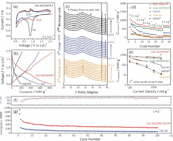
The electrochemical performance of the GaS NS/ SWCNT composite was investigated through cyclic voltam metry (CV) and galvanostatic charge/discharge (GCD), and compared to that of GaS NS. Figure 3a shows CV curves at a scan rate of 0.2 mV s-1. The sharp cathodic peak starts at
1.1 V
in the first cycle, then gradually weakens in the following cycles, and eventually disappears in the tenth cycle, suggesting that the composite film possibly undergoes struc tural change, which could be expressed by the following conversion reactions:1251
GaS+2Li+ +2e- ➔ Ga+Li
2S (2)
as well as the formation of solid electrolyte interphase
(SEI).l57l This process is similar to the conversion reaction of
MoSifSWCNT anode.l41l The obvious plateau at 1.�1.1 V in
the first discharge profile (Figure S3a, Supporting Informa tion) agrees well with the CV result. The cathodic peaks cen tered at 0.6 and 0.1 V could be attributed to the formation of
LiGa and Li2Ga alloy phases, respectively, according to the
following overall reaction:[58,591
(3)
Upon anodic scanning, peaks centered at 0.5 V and 0.8 V, are found, corresponding to de-alloying of LiiGa and LiGa phases to Ga, respectively.l58.59l The absence of sharp peaks in anodic scanning should indicate that the conversion mecha nism of GaS (reaction (2)) is irreversible. Based on the above reactions, a theoretical capacity of around 1053 mAh g-1 for
GaS (assuming four electrons transfer during the lithiation) was obtained. Although the initial discharge capacities of the two materials are similar (1730 mAh g-1, Figure S3a, Sup porting Information), the composite retains a much higher discharge capacity (838 mAh g-1) than that of pure GaS NS (576 mAh g-1) after five cycles at 100 mA g-1 (Figure 3b).
Close examination reveals that broad CV curves (Figure 3a) as well as sloping GCD profiles (Figure S4a, Supporting Information) are found in the composite film, in contrast to the sharp CV peaks and discharge plateau in the GaS NS
(Figure 4b). This implies that the charge-storage mechanism bas changed from traditional battery type to pseudocapaci tive type upon the introduction of SWCNT.[601 Such a crit
ical adjustment, we believe, is important, as charge could be injected/ejected much faster in the case of pseudoca pacitive behavior.115,61,621 As indicated in Figure 2a, the ran
domly distributed SWCNT could simultaneously serve both as the conductive "spacer" and "binder" between the GaS NS, forming a multiscaled hierarchical nanostructure with many surface Li+ storage sites and shortened ion diffusion
paths, which could be responsible for the broad CV and sloping GCD curves in the composite films. In the absence of SWCNT, the GaS NS easily restack to form the multi layered GaS bulk phase (as shown in Figure lb) and thus decrease the surface Li+ storage sites, leading to apparent lower capacity values and fast capacity decay. Actually, the fact that the MC-based conductive composite exhibits a pseu docapacitive charge storage mechanism is not unexpected. Very recently, Dunn and co-workers studied a TiS2 composite electrode, which demonstrated pseudocapacitive intercalated behavior in its 2D nanoscaled morphology that is not exhib ited in the corresponding bulk TiS2.l631 Another study by Park and co-workers also shows that the electrochemical behavior of MoS2 could change from the dominated sluggish diffusion
control to pseudocapacitive provided the layered MoS2 was scaled down into nanometric sheets and percolated with a reduced graphene oxide network.[641
To further understand the charge storage mechanisms, in situ X-ray diffraction (XRD) of the GaS NS/SWCNT composite electrode was performed, and the patterns were
0.4
(a)
Gas NS/SWCNT(c)
•
2
000
�---
.
---.
....
G
a
""
sN
"'
s
=-=
sw
.,..,
c
"'
N
""
T
,...,
0.2
<(
•
Peaks from in-situ cell
':' 0ll 1500
•
( d)
■Gase NS/SWCN
•
GaSNS
E
0.0
--....
...,
-0.2
•Û.4 L.-0.6
-0.8
2.0
... :=i--.... 1.5
:.::;; 1.0
--....
g:i 0.5
"'
....
00.2 mV s·1
�
�
0.0 0.5 1.0 1.5 2.0
Voltage/ V vs Li/Li+
200 400 600 800
10 15 2025
3035
..c
<("
O
.
lA
g
·'
♦
GaSeNS
0.2V
E 1000
1
--....
♦
•
•••0_2 Ag·'
OSA•
.,SWCNT
O.lAg.,
.;
E 02.0V
0
2.0V
1
0.2V
':'
..c
0.2V
<(1
--....
E 0v
0
40500
0
1000
100
10;
••
••••••
.
gl
Ag•1
-1 ••••• ••••• 2 Ag •••••.
...
..
···
·
...
:::::
...
••···
···
...
a
.2:
tttt•
-
··· ···••
t:wi
a...,
.,
._:
::.:1
mtt
05 10 15 20 25 30
Cvcle Number
(e)
Gas NS/SWCNT�
��WCNT GaSNS..
SWCNTG,•Sp NS
5th cycle results at each step
1+...-������-�� ...100
1000
•l
Ccompos�e / mAh g
2 theta /degree
Current Density / mA g
·1
�
100
UJ
90
( f)
<>
0
806
a 8
8o
6g o8e
oe 8
o
Ce
6
80 o 8
0o
o 8 80 oo 66880688 80
o
o 8
oo
g 6 o 80o8088 eo e o 800 8
o
8
0
0
oo
o
6 ooO
o�o0 u
80
1200
":'1000
lAg°'800
--....
600
·"'
400
••
.
···•·... Gas N5/30% SWCNT··· ... .
200
0
...
•••••••• ... •••••••••••••••••••••••••••••••••••••••••• .. ••••• .. •••••••••••••••••••••• GaSNSu
0
10
20
30
40
50
60
7080
90
100
110
Cycle Number
Figure 3. a) Cyclic voltammograms of Gas NS/SWCNT composite (30% SWCNT,
s
µm) at a scan rate of 0.2 mv s-
1.b) Fifth galvanostatic charge/
discharge profiles of SWCNT, Gas NS, and Gas NS/SWCNT composites (30% SWCNT,
s
µm) at a current density of 100 mA g-
1.c) ln situ XRD
patterns of Gas NS/SWCNT composites at different potentials w ith a fix step of 0.2 V versus Li/Li
+. d) Rate performance of SWCNT, Gas, and GaSe
NS-based samples at different current densities ranging from 100 mA g-
1 to2 A g-
1; ail the samples have very similar thickness (5 µm). e) Specific
capacities as a function of current density; here, the capacity at the fifth cycle under each current was selected. 1) Coulombic efficiency and
g) cycling performance of Gas NS and Gas NS/SWCNT composite at 1 A g-
1.recorded at various potentials with a fix potential step of
0.2 V as seen in Figure 3c. Peaks centered at 28
°, 36
°, and 38
°corne from the in situ cell setup. Beside the broad signal
around 23
°, corresponding to the SWCNT scaffold, three
other peaks at, respectively, 11
°, 23
°, and 34
°are found at
open circuit potential (2.0 V), corresponding to (002), (004),
(006) planes of GaS. The evidence of these (001) peaks sug
gests the periodic stacking of the GaS NS. The (001) peaks
are maintained down to 1.2 V, then start to weaken at 1.0 V
and eventually disappear below 0.8 V, indicating the disor
dering of the structure induced by the lithiation of the GaS
during the discharge process, which is irreversible, as no (001)
peaks are recovered upon the following charge cycle. Said
otherwise, there is no evidenœ for the growing of crystalline
GaS in agreement with the irreversible conversion of GaS
(reaction (2)) deduced from the CV, the capacity is majorly
contributed by the Ga alloy process ac.cording to reaction (3).
However, the absence of the Ga and Li
xGa characteristic
peaks suggests that either the crystal growth of these two
species is suppressed, or they are small and disordered.l
59l
The rate performances are shown in Figure 3d. Com
pared to pure GaS NS, the GaS NS/SWCNT composite dis
plays much better capacity and rate capability (Figure 3e).
For example, at 2 A g-
1,the specific capacity of the GaS NS/
SWCNT composite is 530 mAh g-
1,almost six times higher
than that of pure GaS NS (92 mAh g-
1 ).When the current
is switched back to 100 mA g-
1after 25 cycles, the capacity
returns to 700 mAh g-
1.GCD profiles of two electrodes
at various current densities could be seen in Figure S4a,b
(Supporting Information). We believe the rapid capacity
decay of GaS NS could be attributed to the absence of
SWCNT, which provides the efficient conductive network
and maintains the structural integrity. Moreover, the compos
ite's capacity greatly exceeds that of GaS NS and SWCNT
when the current density is beyond 200 mA g-
1,indicating
that the synergistic effect between the two components bas
(a)
10'(b)
.---
.. -•,
103(d) .,,•-•
/
·
-
·
�
<( I • ',.,_..
_
.,.,
_
�
•
� �
/
/
�
! !
.
1
/
j
t
·
1
1
·
-
■·
-;
...�
·1: 10'J
-•-PureGaS -■-5%SWCNT -•-10%, _.,._ 20%+-
0 ,, ---50% ,■ --100 mA g"1■
l / --soomAg" 10, ■ -■-2 Ag·• 101 +.-...---�����...--�-1 '-.---,.---,--+ 100 1000 ·1 Current Density / mA g 0 20 40 60SWCNT /%
-•-PureGaS -■-5%SWCNT -Â- 10%, -T- 20%+-
<� '<>, ---<11-50%//
/• -•-lOOmAg ·1■
·l / -■-SOO�Ag�
<( ■ -■-2 Ag lo' 1o'+,-,...--�����...--�---< '-.---.---,.----+ 100 1000 -1 Current Density / mA g 0 20 40 60SWCNT /%
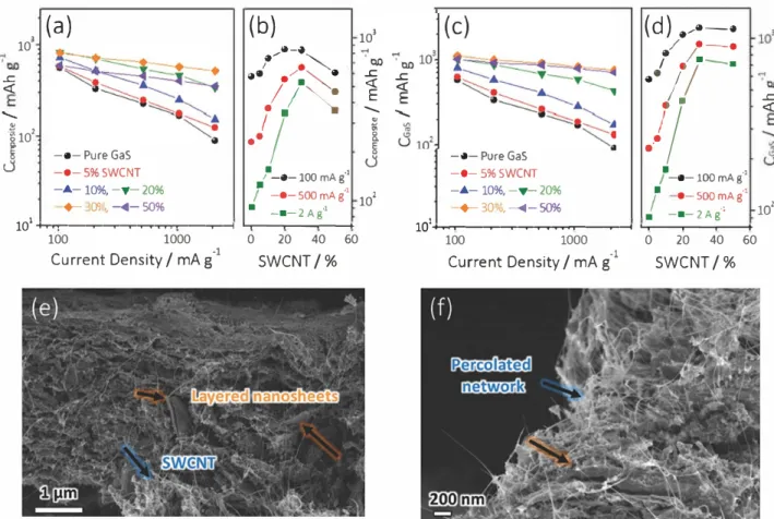
Figure 4. Specific capacities of Gas NS/SWCNT composites as a function of a) current density and b) SWCNT-loading fractions. Here, the capacity at the fifth cycle under each current was selected. Utilization of Gas NS calculated based on Equation (4) as a function of c) current density and d) SWCNT loading fraction. SEM images of cycled Gas NS/SWCNT electrode after 100 cycles at e) low and f) high magnification.
been the reason for the superior Li+ storage performances.
The cycling performances of GaS NS and GaS NS/SWCNT are evaluated at a high rate (1 A g-1), as shown in Figure 3f,g. GaS NS exhibits a low first cycle Coulombic efficiency (iCE, 19%; Figure 3f) and a poor lifetime performance (only 77 mAh g-1 is retained after 100 cycles, Figure 3g). After
embedding the GaS NS in the SWCNT scaffold, both the first cycle CE and the capacity retention have been improved con siderably (iCE = 60% and retains 300 mAh g-1, Figure 3g). The improved iCE should be ascribed to the enhanced elec trical conductivity and mechanical property brought by the SWCNT-percolated network. Further increasing of iCE could be realized by adding Jess SWCNT with higher conductivity but lower surface area. As such, the irreversible capacity Joss from SEI formation is minimized. Although the iCE of the composite is moderate, it is much higher than the graphene/ SWCNT/nickel composite anode material (iCE = 30% ).(651
The rapid capacity decay in the first ten cycles could be attributed to the irreversible GaS conversion, as seen in Figure 3a,c. The graduai capacity decay phenomenon is com monly observed in conversion/alloy-type electrodes and has been attributed to the incomplete conversion, pulveriza tion, and Joss of electrical contact with the SWCNT upon cycling.l13,57J Moreover, the dissolution and shuttling of inter
mediate Li2S could be responsible for the capacity fading, similar to the cycling issues that exist in Li-sulfur batteries. Since this is an early-stage report on the GaS NS/SWCNT
composite, there is certainly much scope to improve the cycle life by gaining increased understanding of its electrochemical process, i.e., ensuring intimate contact between the active GaS and the SWCNT scaffold, facilitating more complete conversion and alloying processes, etc.
GCD curves of GaSe NS and GaSe NS/SWCNT are shown in Figures S3c and S4c,d (Supporting Information), revealing first discharge capacities of 1090 and 1320 mAh g-1,
respectively. A more sloping curve is found in the composite in sharp contrast to plateaus seen for the GaSe NS at ail cur rent densities, further confirming that the addition of SWCNT is beneficial for increasing the Li+ storage sites, shortening ion
diffusion paths and resulting in a pseudocapacitive behavior. The rate performances of GaSe NS and GaSe NS/SWCNT are summarized in Figure 3d,e. The composite shows a discharge capacity of 713 mAh g-1 at 100 mA g-1 and 413 mAh g-1 at 2 A g-1, slightly lower capacity values but similar rate capa bilities compared to the GaS NS/SWCNT counterpart. Therefore, GaS NS was selected for fabricating MC NS/ SWCNT films with different compositions and thickness. The capacities normalized to the total mass of the electrodes are plotted as a function of current density and SWCNT loading fraction as seen in Figure 4a,b. The rate performance of the composites can be found in Figure SS (Supporting Infor mation). Both the capacities and the rate performances are remarkably improved upon increasing the SWCNT loading fractions from 5% to 30%, consistent with the improvement
in electrical conductivity as well as mechanical properties
demonstrated by Figure 2b-<I. However, excessive SWCNT
(50%) addition results in a smaller portion of redox-active
GaS NS in the composite and thus decreases the capacity
substantially, as seen in Figure 4a,b. While it is of more prac
tical importance to investigate the specific capacities nor
malized to the total composite mass, it is also fundamentally
valuable to understand the utilization of the GaS NS, more
precisely how their inherent capacity contributes to the
total capacity of the composite electrode. The utilization of
GaS NS in each composite was quantitatively determined
according to Equation (4):
cG
.s = ( ccomposite -CswcNT
X%swCNT )!%
Gas
(4)\Vhere CGaS> C
composiw and CswcNT represent, respectively,the specific capacity per GaS NS, composite, and SWCNT,
while %swcNT and %Ga
s are the mass loading fractions of
the SWCNT and GaS NS, respectively. Here, the CswcNT
in each composite is supposed to be the same as that of
Fîgure 3d. Fîgure 4c plots the utilization of GaS NS in var
ious composites as a function of current density. When
increasing the %swCNT from 5% to 50%, the C
Gas increases
dramatically at first and then saturates (Fîgure 4d), sug
gesting that 30% SWCNT seems to allow the GaS NS to
reach its intrinsic capacity values, as shown by the plateau.
If so, then the corresponding capacity at the plateau should
match the theoretical value based on Equations (2) and (3).
Encouragingly, the CGas at 100 mA g-
1agrees well with the
theoretical capacity (1107 vs 1053 mAh g-1, respectively). As
for the GaSe NS, its utilization reaches 928 mAh g-
1in the
composite at 100 mA g-
1.Such a remarkably high capacity
per MC NS component greatly exceeds that of the atomic
layer-deposited GaSx-SWCNT composite (766 mAh g-
1).l
241
The electrochemical impedance spectroscopy (EIS) in
Figure S6 (Supporting Information) also suggests that by
gradually adding SWCNT up to 30%, the semicircle at high/
medium-frequency region decreases, implying a smaller
charge-transfer resistance (R
01)and easier semidiffusion pro
cess of Li
+into the GaS NS host. The effect of mass loading
on the areal capacity of GaS NS/SWCNT composite is ana
lyzed in detail in Figures S7-S10 (Supporting Information).
After cycling, the GaS NS/SWCNT composite still preserves
its 2D layered morphology, demonstrating the percolated
network maintains the structural integrity upon repeated
charging/discharging (Figure 4e,f).
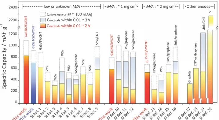
Figure S compares the electrochemical performances of
MC-containing electrode systems in detail (note that Table Sl
(Supporting Information) provides details and references). lt
should be specially noted that, in order to eliminate the effect
of the materials' morphology on the capacities, only materials
with a 2D layered structure, such as nanosheets, nanoflakes,
or nanoplatelets, were chosen from the large MC family.
We emphasize that it is rather challenging to make a direct
comparison among various systems due to a large number of
variables, such as mass loading/film thickness, potential range,
binder/conductive additive fractions, and nanosheet size.
Taking this into account as much as possible, firstly the litera
ture-specified capacities were normalized based on the mass
of active MC and total electrode, and then categorized the
values according to the mass loading as well as the potential
2400 1--- low or unknown M/A---➔ 1-M/A:
~
1 mg cm·2
-I
1- M/A:
~
2 mgcm·�-1 1-0ther anodes--I
,_
2200
'-;'�
tl.O V)� 1200
E
-... 1000
.-!=u
800
600
u
�
u
400
(1)a.
(./)200
0[.J
Cactlvematerlal@~
100mA/g
[J
Celectrode within 0.01 ~ 3 V
D
Caectrode
within 0.01 ~
2
V
,_
z�
�
z V)...
..
C..
_,::; Q.�
..,
0,_
z u v\Figure 5. Comparison of the specific capacities of this work
tovarious 20 MC-containing electrode systems when normalized
tothe mass of
active MC as well as the total electrode material. Values are classified according
tothe mass loading and potential range. Table 51 (Supporting
Information) provides details and references. For the purpose of comparison, we also include graphite, CNT/graphene and Si-based anodes.
range. It is worth mentioning that an anode with lower poten tial is more desirable for achieving a higher energy/power density in LiBs. Unlike the half-cell configuration that emphasizes the discharge capacity regardless of the electrode being anode or cathode, a full-cell battery system relies on the charge capacity of the anode. Therefore, for those systems tested in the 0.01-3 V window, the charge capacities that were achieved in the range 0.01-2 V were extracted to facilitate our comparison. The compiled plot shows that our binder free GaS NS/SWCNT and GaSe NS/SWCNT flexible com posites perform much better than any other 2D MC-based electrode systems in terms of capacity per active MC and per electrode in the 0.01-2 V window. For example, the utilization of GaS NS reached remarkably high (1107 mAh g-1). In addi tion, our composite film outperforms most other electrode systems in the high-mass loading region (2 mg cm-2), except for the SnS/graphene anode by Zhao et al, who tested the composite at a lower current density.1161 This clearly indicates the advantages of the flexible, binder-free composites and highlights its state-of-the-art performance.
3. Conclusion
In summary, the facile, environmentally friendly produc tion of multiscaled hierarchical GaX NS/SWCNT hetero structures is demonstrated. Through a colloidal solution processing approach, the NS matrix embeds well within the SWCNT percolated network, enabling excellent rate capa bility and high specific capacity (838 mAh g-1 in GaS NS and
713 mAh g-1 in GaSe NS) as the LiB anode material. More
over, due to the efficient Li+ diffusion and electron transport
kinetics, the composite film exhibits remarkably high utiliza
tion of GaX NS (1107 mAh g-1 in GaS NS and 928 mAh g-1
in GaSe NS), demonstrating electrochemical performances competitive with those of other reported 2D MC-based elec trode systems. This work opens up vast opportunities for other families of MC NS to be scalably processed into flex ible conductive composite films with a broad range of appli cations such as wearable electronics and optoelectronics, energy storage systems, sensors, and fuel cells.
4. Experimental Section
Exfoliation of MC NS and Preparation of SWCNT Dispersion: Gas NS were obtained through lPE of commercial Gas powder (99.999% GaS-05-P, American Elements) using an ultrasonic bath (P30 H Ultrasonic from Fischer scientific) in IPA.1501 First, the Gas powder was added into 20 ml of IPA at a concentration of 45 mg ml-1, then the suspension was sonicated for 6 h at an amplitude of 100% and a frequency of 37 kHz. During sonication, the temperature of the bath was cooled to 20-30 °C by contin uous flow of cooling water. Once sonicated, the dispersion was subjected to centrifugation (Hettich Mikro 220R) for 180 min at 1000 rpm. The top 60% supernatant was collected while the sed iment was recycled to produce an adequate quantity of Gas NS. SWCNT (P3-CNT, Carbon Solutions, Inc.) was dispersed in IPA at a concentration of 0.1 mg ml-1 using bath sonication. Ga Se NS
was similarly prepared by sonication the commercial GaSe pow ders in IPA.
Flexible MC NS/SWCNT Composite: The composites were pre
pared through a facile vacuum filtration approach of blended dispersion though a polyethylene membrane (Celgard K2045, 0.06 µm pore size). Severa! Gas NS/SWCNT composite films were prepared with SWCNT contents being 5%, 10%, 20%, 30%, and 50%, respectively, while keeping the filtrated volume constant (20 ml). Composites with different thickness were also prepared by con trolling the filtrated volume to 20, 40, 80, and 160 ml, respec tively. To avoid degradation over time, the films (including the membrane) were immediately transferred to a glove box (oxygen and water content <1 ppm). The natural dried films were then eut into individual electrodes with 7 mm x 7 mm size (geometric area
.. o.s cm2). lt is worth noting that the attached membrane was
utilized as a second separator in the coin cells. This was clearly different from many reported freestanding electrodes, which were obtained through complicated peeling off or film transfer procedures.139•661 For the GaSe NS/SWCNT composite, the SWCNT loading fraction was controlled at 30%.
Materials Characterization: The SEM images were obtained on
a Zeiss Ultra Plus (Carl Zeiss, Germany) working at 2 keV of acceler ation voltage. EDX was performed in the same microscope and ana lyzed using INCA program. TEM analysis of the MC NS and SWCNT was performed on an FEI Titan at 300 kV (FEI, USA). The nanosheet dispersion was drop-casted onto holey carbon grids (Agar Scien tific, UK). The flake dimensions were statistically analyzed on TEM by measuring the longest axis of the nanosheets and assigning it as the length. Optical spectroscopy was done on Gas NS disper sion using an UV-vis absorbance spectroscopy (Cary 6000i Spec trometer, Agilent, USA). Both the extinction and absorption spectra of the dispersion were measured using an integrating sphere that subtracted the absorption spectra from the extinction spectra. To show the quality and defects of the as-exfoliated Gas NS, X-ray photoelectron spectroscopy and Raman spectroscopy were con ducted. XPS was performed using monochromated Al Ka X-rays from an Omicron XM1000 Mkll X-ray source with an EA125 energy analyzer, which yielded a maximum energy resolution of .. o.65 eV. Ali the binding energy scale was referenced to the aliphatic carbon 1s core-level at 284.8 eV. Raman spectra of Gas NS were acquired using a WITec Alpha 300 R with a 532 nm excitation laser at a power of .. 150 µW. A 100x objective was used with a spectral grating of 600 lines mm-1. Characteristic spectra were obtained by averaging 20 discrete point spectra for each sample. For the composite electrodes, Raman maps were obtained by acquiring 80 x 80 spectra over an area of 20 x 20 µm. Maps representing the presence of SWCNT were generated by mapping the intensity of the SWCNT G band whereas the presence of Gas was represented by the intensity of the Gas A\g band. The DC electrical conductivity of the composites was measured using a two-point probe technique. Two parallel electrode contacts were created on the film surface using conductive silver paint (Agar Scientific). The resistance of each sample was measured using a Keithley 2400 source meter. The electrode thickness was determined by a digital micrometer (Mitutoyo). ln order to perform mechanical measurements, the Gas NS/SWCNT was peeled off composites (with different SWCNT loading fractions) after vacuum filtration. The free-standing films were then eut into stripes, 2.25 mm wide. The mechanical meas urements were conducted on the Zwick tensile tester using a
gauge length of 5 mm and a strain rate of 1 mm min-1. Each data point was an average of four measurements.
Electrochemico/ Characterization:
The electrochemical per formances of the Gas and GaSe NS/SWCNT flexible composites were investigated using CR-2032 coin cells. Two layers of poly• propylene membrane (K2045 Coated PP, Celgard LLC, Charlotte, NC) were used as a separator. The composite electrode (attached on the PP) was used as the working electrode while a lithium metal dise with a diameter of 16 mm was used as both the counter and reference electrodes. The electrolyte was 1 M lithium perchlorate (LiCIO,.) dissolved in ethylene carbonate and dimethyl carbonate in a volume ratio 1:1. Electrochemical tests were performed through 0/, GCD, and EIS with a voltage range of 0.05-2 V on a potentiostat (.VMP3, Biologie). ln the 0/, electrodes were cycledfor ten times at 0.2 mV s-1. For GCD, tests were conducted with
current densities ranging from 100 to 2000 mA g-1. The capacities
reported here were those obtained from the sixth discharge profile at each current density and normalized to either the mass of active material (Gas NS) or the total mass of composite (Gas NS/SWCNl). The cycling performance of the electrodes was evaluated at
1000 mA g-1 for 100 cycles. The EIS was conducted at the open-circuit
potential with the AC frequencies ranging from 200 kHz to 10 mHz.
Supporting Information
Supporting Information is available from the Wiley On/ine Library
or from the author.
Acknowledgements
C.F.Z. and S.-H.P. contributed equal/yto this work. V.N., C.F.Z., S.-H.P.,
A.S.-A., O.R. wish to acknow/edge the following funding support:
SFI AMBER, SFI PIYRA, ERC StG 20NanoCaps, ERC PoC 2DUSD, ERC
PoC 20/nk, FP7 MC ITN MoWSeS, Horizon2020 NMP Co-Pilot. J.N.C.
acknowiedges the ERC SEMANT/CS and SFI (11/Pl/1087) for {inancial
support.
N.M.
was supported
by
the SFI under 15/SIRG/3329, and
N.C.B. and G.S.D. acknow/edge SFI P/_10/IN.1/I3030. Z.L. was sup
ported by China Scho/arship Council (Grant No. 201304490006).
Aliauthors wish to thanks the Advanced Microscopy Laboratory ('AML)
in
CRANN,
Trinity College. S. O'Brien and
A.Pok/e are a/so acknowi
edged and thanked for the he/p provided. S. O'Brien,
A.Pok/e, and
J. Coe/ho are appreciated for the experimental he/p.
Conflict of lnterest
The authors dec/are no conflict of interest.
(1) P. G. Bruce, B. Scrosati, J.-M. Tarascon,
Angew. Chem. /nt. Ed.
2008,
47,
2930.(2) J. B. Goodenough, Y. Kim,
Chem. Mater.
2010,22,
587.(3) C. Zhang, T. M. Higgins, S.-H. Park, S. E. O'Brien, D. Long, J. N. Coleman, V. Nicolosi,
Nono Energy
2016, 28, 495.(4) C. Zhang, K. B. Hatzell, M. Boota, B. Dyatkin, M. Beidaghi,
D. Long, W. Qiao, E. C. Kumbur, Y. Gogotsi,
Carbon
2014, 77, 155.(5) R. Chen, T. Zhao, W. Wu, F. Wu, L. Li, J. Qian, R. Xu, H. Wu, H. M. Albishri, A. S. AI-Bogami, D. A. EI-Hacly, J. Lu, K. Amine,
NanoLett.2014, 14,
5899.(6) P. Yu,/.
Electrochem. Soc.
1999,146,
8.(7) C, Zhang, Y. Xie, G, Sun, A. Pentecost, J, Wang, W. Qiao, L. Ling, D. Long, Y. Gogotsi,/.
Electrochem. Soc.
2014,161,
1486.(8) L. Ji,
z.
Lin, M. Alcoutlabi, X. Zhang,Energy Environ. Sei.
2011,4,
2682.
(9) Y.-G. Guo, Y.-S. Hu, W. Sigle, J. Maier,
Adv. Mater.
2007,19,
2087. (10) L. He, C. Wang, X. Yao, R. Ma, H. Wang, P. Chen, K. Zhang,Carbon
2014,
75,
345.(11) Y. Wu, H. Wu, S. Luo, K. Wang, F. Zhao, Y. Wei, P. Liu, K. Jiang, J. Wang, S. Fan,
RSC Adv.
2014,4,
20010.(12) Y. Sun, S.-B. Yang, L.-P. Lv, 1. Lieberwirth, L.-C. Zhang, C.-X. Ding, C.-H. Chen,/.
Power Sources
2013,241,
168.(13) J. Chang, X. Huang, G. Zhou, S. Cui, P. B. Hallac, J. Jiang,
P. T. Hurley, J.
Chen,Adv. Mater.
2013,26,758.
(14) F. Du, H. Tang, L. Pan, T. Zhang, H. Lu, J. Xiong, J. Yang, C. Zhang,
Electrochim. Acta
2017,235,
690.(15) C. Zhang, R. Maloney, M. R. Lukatskaya, M. Beidaghi, B. Dyatkin, E. Perre, D. Long, W. Qiao, B. Dunn, Y. Gogotsi, /.
Power Sources
2015,274,
121.(16) S. Y. Liu, X. Lu, J. Xie, G. S. Cao, T. J. Zhu, X. B. Zhao,
ACS Appl.
Mater. Inter.
2013,5,
1588.(17) L. Kong, C. Zhang, J. Wang, W. Qiao, L. Ling, D. Long,
Sei. Rep.
2016, 6, 21177.
(18) Y. Wei, Y. Tao, C. Zhang, J. Wang, W. Qiao, L. Ling, D. Long,
Electro
chim. Acta
2016,188,
385.(19) L. Kong, C. Zhang, J. Wang, D. Long, W. Qiao, L. Ling,
Mater. Chem.
Phys. 2015,
149-150,495.
(20) C. Zhang, M. Beidaghi, M. Naguib, M. R. Lukatskaya, M.-Q. Zhao,
B. Dyatkin, K. M. Cook, S. J. Kim, B. Eng, X. Xiao, D. Long, W. Qiao,
B. Dunn, Y. Gogotsi, Chem. Mater. 2016,
28,
3937.(21) M. Chhowalla,
z.
Liu, H. Zhang,Chem. Soc. Rev.
2015,44,
2584.
(22) C. Zhang, S. Pinilla, N. McEvoy, C. P. Cullen, B. Anasori, E. Long, S.-H. Park, A. Seral-Ascaso, A. Shmeliov, D. Krishnan, C. Morant, X. Liu, G. S. Duesberg, Y. Gogotsi, V. Nicolosi,
Chem. Mater.
2017,29,
4848.(23) C. Zhang, S. J. Kim, M. Ghidiu, M.-Q. Zhao, M. W. Barsoum, V. Nicolosi, Y. Gogotsi,Adv.
Funct. Mater. 2016, 26,
4143.(24) X. Meng, K. He, D. Su, X. Zhang, C. Sun, Y. Ren, H.-H. Wang,
W. Weng, L. Trahey, C. P. Canlas, J. W. Elam,
Adv. Funct. Mater.
2014,
24,
5435.(25) C. Wu, J. Maier, Y.
Yu,Adv. Mater.
2016,28,
174.(26) Q. Zhang, S. Tan, R. G. Mendes, Z. Sun, Y. Chen, X. Kong, Y. Xue, M. H. Rümmeli, X. Wu, S. Chen, L. Fu,
Adv. Mater.
2016,28,
2616.(27) J. Xiao, D. Choi, L. Cosimbescu, P. Koech, J. Liu, J. P. Lemmon,
Chem. Mater.
2010,22,
4522.(28) H. S. S. R. Matte, A. Gomathi, A. K. Manna, D. J. Late, R. Datta, S. K. Pati, C. N.R.
Rao,Angew. Chem. lnt. Ed. 2010, 49,
4059. (29) D. Chen, G. Ji, B. Ding, Y. Ma, B. Qu, W. Chen, J. Y. Lee,lnd. Eng.
Chem. Res.
2014,53,
17901.(30) C. Zhang, X. Liu, V. Nicolosi,
Bioenerg.: Open Access
2016,5,
1. (31) A. O'Neill, U. Khan, J. N. Coleman,Chem. Mater.
2012,24,
2414. (32) R. J. Smith, P.J. King, M. Lotya, C. Wirtz, U. Khan, S. De, A. O'Neil�G. S. Duesberg, J. C. Grunlan, G. Moriarty, J. Chen, J. Wang, A. 1. Minett, V. Nicolosi, J. N. Coleman,
Adv. Mater.
2011,23,
3944. (33) V. Nicolosi, M. Chhowalla, M. G. Kanatzidis, M. S. Strano,J. N. Coleman,
Science 2013, 340,
1226419.(34) Y. Lu, X. Yao, J. Yin, G. Peng, P. Cui, X. Xu,
RSCAdv.
2015,5,
7938.(35) K. Chang, W. Chen,
ACS Nono
2011,5,
4720.(36) Y. Liu, X. He, D. Hanlon, A. Harvey, J. N. Coleman, Y. Li,
ACS Nono
2016,10,
8821.(37) T. Fujita, Y. lto, Y. Tan, H. Yamaguchi, D. Hojo, A. Hirata, D. Voiry, M.Chhowalla, M. Chen, Nanosca/e 2014, 6, 12458.
(38) X. Xiao, C. Zhang, S. lin, L. Huang, Z. Hu, Y. Cheng, T. Li, W. Qiao, D. Long, Y. Huang, L. Mai, Y. Gogotsi, J. Zhou, Energy Storage Mater. 2015, 1, 1.
(39) X. Xiao, Z. Peng, C. Chen, C. Zhang, M. Beidaghi, Z. Yang, N. Wu, Y. Huang, L. Miao, Y. Gogotsi, J, Zhou, Nono Energy 2014, 9, 355,
(40) N. A. Kumar, M. A. Dar, R. Gui, J.-B. Baek, Mater. Today 2015, 18,
286.
(41) Y. Liu, X. He, D. Hanlon, A. Harvey, U. Khan, Y. Li, J. N. Coleman,
ACS Nono 2016, 10, 5980.
(42) A. V. Murugan, M. Quintin, M.-H. Delville, G. Campet, C. S. Gopinath, K. V ijayamohanan, /. Power Sources 2006, 156,
615.
(43) P. Hu, L. Wang, M. Yoon, J. Zhang, W. Feng, X. Wang, Z. Wen, J. C. Jdrobo, Y. Miyamoto, D. B. Geohegan, K. Xiao, Nono Lett.
2013, 13, 1649.
(44) S. Yang, Y. Li, X. Wang, N. Huo, J.-B. Xia, S.-S. li, J. li, Nanosca/e
2014, 6, 2582.
(45) Y. Hernandez, V. Nicolosi, M. Lotya, F. M. Blighe, Z. Sun, S. De, 1. T. McGovern, B. Holland, M. Byrne, Y. K. Gun'Ko, J. J. Boland, P. Niraj, G. Duesberg, S. Krishnamurthy, R. Goodhue, J. Hutchison, V. Scardaci, A. C. Ferrari, J. N. Coleman, Nat. Nanotechno/. 2008, 3,563.
(46) J. N. Coleman, M. Lotya, A. O'Neill, S. D. Bergin, P. J. King, U. Khan,
K. Young, A. Gaucher, S. De, R. J. Smith, 1. V Shvets, S. K. Arora, G. Stanton, H.-Y. Kim, K. Lee, G. T. Kim, G. S. Duesberg, T. Hallam, J. J. Boland, J. J. Wang, J. F. Donegan, J. C. Grunlan, G. Moriarty, A. Shmeliov, R. J. Nicholls, J. M. Perkins, E. M. Grieveson,
K.Theuwissen, D. W. McComb, P. D. Nellist, V. Nicolosi, Science
2011, 331, 568.
(47) T. M. Higgins, D. McAteer, J. C. M. Coelho, B. Mendoza Sanchez, Z. Gholamvand, G. Moriarty, N. McEvoy, N. C. Berner, G. S. Duesberg, V. Nicolosi, J. N. Coleman, ACS Nono 2014, 8,
9567.
(48) D. McAteer, Z. Gholamvand, N. McEvoy, A. Harvey, E. O'Malley, G. S. Duesberg, J. N. Coleman,ACS Nono 2015, 10,672.
(49)K. Allakhverdiev, J. Hagen, Z. Salaeva, Phys. Status So/idi 1997,
163, 121.
(50) A. Harvey, C. Backes, Z. Gholamvand, D. Hanlon, D. McAteer,
H. C. Nerl E. McGuire, A. Seral-Ascaso, Q. M. Ramasse,
N. McEvoy, S. Winters, N. C. Berner, D. McCloskey, J. F. Donegan, G. S. Duesberg, V. Nicolosi, J. N. Coleman, Chem. Mater. 2015, 27,
3483.
(51) C. Backes, B. M. Szydlowska, A. Harvey, S. Yuan, V. Vega-Mayoral, B. R. Davies, P.-L. Zhao, D. Hanlon, E. J. G. Santos, M. 1. Katsnelson, W. J. Blau, C. Gadermaier, J, N. Coleman, ACS Nono 2016, 10, 1589,
(52) D. J. Late, B. Liu, H. S. S. R. Matte, C.N.R. Rao, V. P. Dravid, Adv. Funct. Mater. 2012, 22, 1894.
(53) P. J. King, T. M. Higgins, S. De, N. Nicoloso, J. N. Coleman, ACS
Nono 2012, 6, 1732.
(54) D. Stauffer, A. Aharony, Computer (Long. Beach. CaliO. 1994, 1,
192.
(55) M. S. Dresselhaus, G. Dresselhaus, R. Saito, A. Jorio, Phys. Rep.
2005, 409, 47.
(56) G. Duesberg, W. Blau, H. Byrne, J. Muster, M. Burghard, S. Roth, Chem. Phys. Lett. 1999, 310, 8.
(57) N. Nitta, G. Yushin, Part. Part. Syst. Charact. 2014, 31,317.
(58) J. Saint, So/id State lonics 2005, 176, 189.
(59) H. Senoh, H. Kageyama, T. Takeuchi, K. Nakanishi, T. Ohta, H. Sakaebe, M. Yao, T. Sakai, K. Yasuda, /. Power Sources 2011, 196, 5631.
(60) V. Augustyn, P. Simon, B. Dunn, Energy Environ. Sei. 2014, 7, 1597. (61) V. Augustyn, J. Come, M. Lowe, J. W. Kim, P.-L. Taberna,
S. H. Tolbert, H. D. Abruila, P. Simon, B. Dunn, Nat. Mater. 2013,
12, 518.
(62) C. Zhang, Y. Xie, M. Zhao, A. E. Pentecost, Z. Ling, J. Wang, D. Long, L. Ling, W. Qiao, ACS Appt. Mater. Interfaces 2014, 6, 9751.
(63)G. A. Muller, J. B. Cook, H.-S. Kim, S. H. Tolbert, B. Dunn, Nono
Lett. 2015, 15, 1911.
(64) Q. Mahmood, S. K. Park, K. D. Kwon, S.-J. Chang, J.-Y. Hong,
G. Shen, Y. M. Jung, T. J. Park, S. W. Khang, W. S. Kim, J. Kong,
H. S. Park, Adv. Energy Mater. 2016, 6, 1501115.
(65) S.-H. Bae, K. Karthikeyan, Y.-S. Lee, 1.-K. Oh, Carbon 2013, 64,
527.
(66)J.-Z. Wang, L. Lu, M. Lotya, J. N. Coleman, S.-L. Chou, H.-K. Liu,