an author's http://oatao.univ-toulouse.fr/23308
https://cfm2017.sciencesconf.org/130781/document
Labanieh, Ahmad and Garnier, Christian and Ouagne, Pierre and Dalverny, Olivier and Soulat, Damien Analysis of the multilayer woven fabric behaviour during the forming process. Focus on the loss of cohesion within the woven fibre network. (2017) In: 23ème Congrès Français de Mécanique, 28 August 2017 - 1 September 2017 (Lille, France).
Analysis of the multilayer woven fabric behaviour
during the forming process. Focus on the loss of
cohesion within the woven fibre network.
A. R. LABANIEH
a, C. GARNIER
b, P. OUAGNE
c, O. DALVERNY
d,
D. SOULAT
e,
a : Génie de Production (LGP), ENIT, Tarbes, France. Email :
[email protected]
b : Génie de Production (LGP), ENIT, Tarbes, France. Email :
[email protected]
c : Génie de Production (LGP), ENIT, Tarbes, France. Email :
[email protected]
d : Génie de Production (LGP), ENIT, Tarbes, France. Email :
[email protected]
e : Génie et Matériaux Textiles (GEMTEX), ENSAIT, Roubaix, France. Email :
[email protected]
Abstract
The composite manufacturing process occupies a more prominent place in the aerospace and automotive industries due to the lightweight and high performance of the fibre reinforced polymers. The first step in this manufacturing process consists in forming a flat textile reinforcing structure into a designed (tailored) form. The woven textile preform is widely used in the composite manufacturing for its good draping and flexibility properties. The quality of the final woven composite part depends on the fibre distribution and orientation. It also depends on the absence or presence of forming defects. The reasons of occurrence of defects are related to tool geometry, process parameters, textile characteristics, relative plies orientation, inter-ply friction and fabric-tools interaction. Loss of cohesion in the woven fibre network (intra-ply yarn sliding) is a frequent defect in the forming process and it is expected when the cohesion between the yarns is weak or when the blank holder pressure is high. However, the mechanism of formation of this defect is not fully understood. In the present study, forming experiments with friction-based holder have been conducted for one layer of 2x2 twill woven carbon fabric (HexForce 48600 U 1250) in two fabric orientations and also for two plies of this fabric with different relative plies orientation. The occurrence of the intra-ply yarns sliding has been observed in the different configurations and as a function of the blank holder pressure. A correlation between the occurrence of this defect and the fabric orientation has been observed. Otherwise, the effect of the fabric orientation, number of plies, relative plies orientation and blank holder pressure on the recorded forming force and on the fabric in-plane shear is also reported and analysed. That permits to better understand the multilayer woven fabric behaviour during forming and this leads to a better understanding of the loss of cohesion defect (intra-ply yarn sliding) within the woven fibre network.
Keywords: composite manufacturing process, forming of multilayer woven
fabric, loss of cohesion within the woven fibre network.
1 Introduction
The forming technology of initially flat textile material into a 3D shaped form is the basic step in the manufacturing process of structural high performance composite [1]. The enormous design variety of textile material provides wide possibilities for this technology to respond to the variant use and different application conditions. The 2D woven fabric either as mono- or multilayer is widely employed in this technology. However, the fabric may exhibits different defect types during the forming process depending on the fabric specification, inter-ply friction, process parameters and tool geometry [2]. The mechanisms of occurrence of these defects are not fully understood neither for mono- nor multiplies.
The intra-ply yarns sliding defect between warp and weft yarns representing a loss of cohesion within the woven fibre network occurs frequently during the forming of a woven fabric [3], [4]. This defect is attributed to the weak cohesion between yarns in the fabric [5] and to the strong blank holder load [3]. Generally, the blank holder load is increased to avoid the formation of the wrinkles once the characteristic locking shear angle is exceeded [6]. Therefore, the blank holder load has to be set in a range to avoid these two phenomena. The mechanisms of initiation and evolution of this defect during the forming process are not fully understood. The boundary conditions and fabric properties effects on its occurrence are not precisely defined. In the present paper an experimental study has been conducted on forming a mono- and two plies twill 2/2 woven carbon fabric via a friction-based blank holder forming machine. This study contributes to explore the effects of the blank holder load and fabric orientation on the fabric forming behaviour and the intra-ply yarns sliding phenomena. Section 2 of this paper defines the used fabric geometrical properties. Section 3 describes the friction-based blank holder forming machine employed in this study and the experiment conditions. Finally, section 4 presents the observed and analysed results.
2 Material
The experimental study presented in this paper has been conducted using commercial carbon fabric for aeronautic and transport application designated as “HexForce 48600 U 1250”. The fabric is made of “AS4 C GP 12K” carbon fibre for both warp and weft yarns, which are not twisted and have linear densities of 0.8 g/m. The yarn is composed of 12’000 continuous filaments and it is non-powdered. The weave style of the fabric is twill 2/2 and it is constructed of 3.7 warps/cm and 3.7 wefts/cm with a nominal area density of 600 g/m². The yarns form closed weaves with no gap between adjacent yarns.
3 Method
3.1 Forming machine
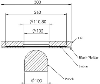
The fabric behaviour during forming process has been explored in this study by means of the experimental forming machine constructed by the GEMTEX laboratory [7, 8]. The machine is composed of three basic parts: punch, die and blank holder, illustrated in Figure 1. The punch with a hemispherical form is mounted on a pneumatic actuator with a controlled mounting speed of 45 mm/s. The punch has 100 mm of diameter
and its initial position is spaced from the fabric. The die is a square flat transparent plate having a central cylindrical hole with constant fillet radius. This conception of the open die permits to observe and measure the fabric deformation during forming tests using CCD camera. Finally, the blank holder is also a flat square plate with an open central hole through which the punch passes. The fabric specimen is placed between the die and the blank holder with the controlled normal load applied on the blank holder by means of four identic pneumatic actuators arranged at square frame corners. This normal blank holder load permits via generated frictional force on the interaction surfaces fabric-die and fabric-blank holder to control the fabric tension during the forming process. The blank holder load has been varied in this experimental study to observe the effect of the process parameters on the fabric behaviour and the forming force applied by the punch. The variation is exerted by means of variation of feed air pressure to the actuators to the following values: 0.025, 0.05, 0.075 and 0.1 MPa that correspond to a normal force by each cylinder equals to 77.9, 155.8, 233.7 and 311.7 N respectively, according to the actuator specifications.
Figure 1: Forming machine scheme with characteristic dimensions
3.2 Specimen conditions
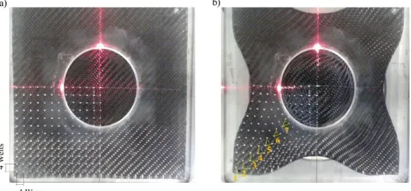
The specimens were designed as a square form with side dimensions of 260 mm. Two configurations have been tailored regarding the ply placement and orientation in the machine relative to the die and blank holder border; in the first configuration, denoted as ply-0, the warp and weft yarns are parallel to die and blank holder borders and in the second configuration, denoted as ply-45, the yarns make an angle of 45° with die and blank holder borders such as the warp and weft yarns are parallel to the diagonals of the square form, Figure 2. The fabric orientations are controlled thanks to an optical laser guide.
Figure 2: ply-0 (a) and ply-45 (b) configuration of the fabric specimen in its initial position, discontinuous line represent warp and weft yarn crossing at the centre
The fabric behaviour has been explored for one ply in the two orientation configurations (ply-0 and ply-45) by varying the blank holder load for the values detailed earlier. At each orientation, the forming test has been performed on at least three specimens for each blank holder load value. The forming force exerted by the punch to give the hemispherical form to the fabric has been recorded via a cell force mounted between the punch and the actuator. Moreover, the fabric in-plane shear behaviour has been observed by measuring the angles between the warp and weft yarns. The measurement has been realised by means of white markers drawn on the fabric at the initial state at crossing points of warp and weft. In both directions, the markers were spaced by three yarns resulting in a resolution of 4x4 yarns corresponding to the fabric unit cell. So a picture is captured for each specimen after forming operation therefore as the die is transparent. Figure 3 shows the marker style on a ply-0 under die plate before and after preforming. On ply-0, the shear angle has been measured at seven points along the diagonal on the flat part of the specimen, as illustrated in Figure 3. The point-1 is placed on the left lower corner of the specimen and the point-7 is placed at the exit of the fabric from the die toward the punch.
Furthermore, the behaviour of the fabric has been explored for two plies in two through thickness sequences regarding the plies orientation designated as following: plies-45/0 and plies-0/45 (lower ply facing punch/upper ply facing die). But the experiments have been performed for only two blank holder loads corresponding to the following air pressure values for the four actuators: 0.05 and 0.075 MPa.
4 Results
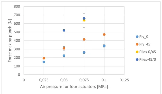
The forming force exerted by the punch in the forming operation under different blank holder loads is presented in Figure 4 for one ply in both orientation configuration (ply-0 and ply-45) as well as for two plies in 0/45 and 45/0 denoted as plies-0/45 and plies-45/0. In all fabric configurations, increasing the blank holder loads has for consequence to augment the forming force because. This is due to the tangential frictional effort on the fabric/die and fabric/holder interaction surface that has for consequence to raise the fabric (yarns) tension.
Figure 5 shows the evaluation of the shear angle on ply-0 at seven points along the specimen diagonal as shown in Figure 3. At the point-7, which corresponds to the exit of the fabric from the die-holder zone toward the punch, the shear angle has similar value for the different blank holder loads (about 48° with a standard deviation of 1.5). That shows the dependency of the shear angle at this position on the punch geometry, where the fabric deforms to fit the punch form, in spite of the blank holder load. However, development of the shear angle from approximately 0° at point-1 to the maximum value at point-7 depends on the holder load. For weak blank holder load, the shear angle increases slightly over the three first points. It is coupled to fabric corner sliding toward the centre. A strong augmentation toward the maximum angle at the point-7 is observed. However, for stronger blank holder loads the angle evolvesgradually from point-1 to point-7 and that is associated to a lack of the fabric corners sliding. This shows the high dependency of the forming force on the fabric tension.
The ply-45 requires a higher forming force in comparison to the ply-0. This is probably due to the difference in yarns length submitted to the tangential frictional force in the die-holder region between both configurations resulting in different yarn tensions. The warp and weft yarns, consumed by the punch, in ply-45 are parallel to the specimen diagonal so they have a longer length in the die-holder region in comparison to the punch-consumed yarns length in ply-0.
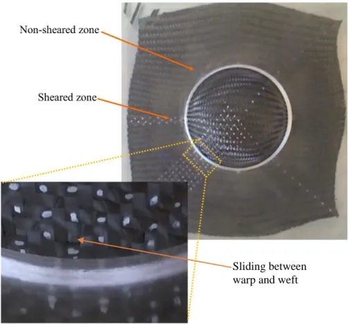
Otherwise, sliding between warp and weft yarns occurs in the useful zone of ply-45, near to exit of the fabric from the die-holder region toward the punch in the non-sheared zone, Figure 6. The sliding extends when higher blank holder pressure is applied. That could be correlated with the effect of yarns length on the generated tension so the diagonal yarns placed in non-sheared zone are subjected to the highest tension that decrease gradually towards sheared zone. Thus the occurrence of the sliding between warp and weft yarns depends on the yarns tension onto the specimen that is related to ply orientation and the applied blank holder load. Otherwise, the sliding is affected also by the cohesion of the textile network that depends on the fibre nature and the weaving style [5].
In two plies configuration (plies-0/45 and plies-45/0) inter-ply sliding occurs because of the difference in yarns deformation from the two plies to obtain the hemispheric form. That implies the ply/ply friction behaviour. Thus the measured forming force is stronger in comparison to ply-0 and ply-45. Otherwise, no effect of the ply order relative to their orientation on the forming force are observed Figure 4. One can
observe that the measured force for the two layers configuration is the addition of the exerted forming force for each ply individually with a small deviation. That could be referred to the poor difference between fabric/tools and fabric-0/fabric-45 friction behaviour in this case.
However, local sliding between warp and weft yarns is seen in ply 0° of both plies-0/45 and plies-45/0. That results from the hanging effect between the yarns from the two plies as the yarns have a different orientation and displacement history during the performing process.
Figure 4: Maximum punch force exerted for one and two plies configuration in different pressure values.
Figure 5: Shear angle at the seven points defined along the specimen diagonal in 0 orientation; the point-1 is placed on the left lower corner of the specimen and the point-7 is placed at the exit of the fabric from the die toward the punch.
0 100 200 300 400 500 600 700 800 0 0,025 0,05 0,075 0,1 0,125 Force m ax b y p u n ch [ N ]
Air pressure for four actuators [MPa]
Ply_0 Ply_45 Plies-0/45 Plies-45/0 -5,00 5,00 15,00 25,00 35,00 45,00 55,00 0 2 4 6 8 Sh ear a n gle [ °] Points on diagonal Ply-0-0,025 Ply-0-0,05 Ply-0-0,075 Ply-0-0,1
Figure 6: Sliding between warp and weft yarns in Ply-45in the non-sheared zone at the exit of the fabric from the die-holder region.
5 Conclusion
The forming behaviour of 2/2 twill carbon fabric into a hemispherical form by using a friction-based blank holder forming machine has been analysed as a function of the blank holder load and fabric orientation for one and two plies configuration. The effect of these parameters on the loss of the fabric network cohesion (intra-ply yarns sliding) has been also observed.
The forming force exerted by the punch to form the shape depends on the fabric tension controlled by the blank holder load. Also, it is affected by the fabric orientation because of the difference in the yarn length under blank holder loads. Otherwise, the fabric tension during the forming process has an important influence on the occurrence of intra-ply sliding between warp and weft yarns.
Inter-plies sliding takes place in forming of two plies with a different orientation (inter-ply angle) because of the difference in the yarns displacement history from the two plies during forming process. This inter-plies sliding is affected by the fabric-fabric interaction friction behaviour that leads to intra-ply yarns sliding that did not occur in one ply such as in ply-0. The mechanism associated to the occurrence of the intra-ply yarns sliding defect as a function of fabric and process parameters will be treated in future works.
Sliding between warp and weft
Reference
[1] Long, A. C. and Clifford M. J., (2007), Composite forming mechanisms and materials characterization chapter 1 of Composite forming technologies Edited by Long A. C., Woodhead Publishing Limited, England.
[2] Allaoui, S., Cellard, C. and Hivet, G. (2015) Composites: Part A Effect of inter-ply sliding on the quality of multilayer interlock dry fabric preforms, COMPOSITES PART A. Elsevier Ltd, 68, pp. 336–345.
[3] Gatouillat, S., Bareggi, A., Vidal-Sallé, E. and Boisse, P. (2013) Meso modelling for composite preform shaping - Simulation of the loss of cohesion of the woven fibre network, Composites Part
A: Applied Science and Manufacturing. Elsevier Ltd, 54, pp. 135–144.
[4] Ouagne, P., Soulat, D., Moothoo, J., Capelle, E. and Gueret, S. (2013) Complex shape forming of a flax woven fabric; Analysis of the tow buckling and misalignment defect, Composites Part A:
Applied Science and Manufacturing. Elsevier Ltd, 51, pp. 1–10.
[5] Allaoui, S., Hivet, G., Soulat, D., Wendling, A., Ouagne, P. and Chatel, S. (2014) Experimental preforming of highly double curved shapes with a case corner using an interlock reinforcement,
International Journal of Material Forming, 7(2), pp. 155–165.
[6] Prodromou, a. G. and Chen, J. (1997) On the relationship between shear angle and wrinkling of textile composite preforms, Composites Part A: Applied Science and Manufacturing, 28, pp. 491– 503.
[7] P.B. Jacquot, P. Wang, D. Soulat, X. Legrand. Analysis of the preforming behaviour of the braided and woven flax/polyamide fabrics. Journal of Industrial Textiles, September 2016; vol. 46, 3: pp. 698-718
[8] Wang P., Legrand X., Boisse P., Hamila N., Soulat D. Experimental and numerical analyses of manufacturing process of a composite square box part: Comparison between textile reinforcement forming and surface 3D weaving. Composites Part B 2015; 78: 26-34.