Science Arts & Métiers (SAM)
is an open access repository that collects the work of Arts et Métiers Institute of
Technology researchers and makes it freely available over the web where possible.
This is an author-deposited version published in:
https://sam.ensam.eu
Handle ID: .
http://hdl.handle.net/10985/14804
To cite this version :
Romain DUBALLET, Olivier BAVEREL, Justin DIRRENBERGER - Space Truss Masonry Walls
With Robotic Mortar Extrusion - Structures - Vol. 18, p.41-47 - 2019
Any correspondence concerning this service should be sent to the repository
Administrator :
[email protected]
Space Truss Masonry Walls With Robotic Mortar Extrusion
R. Duballet
a,c,*, O. Baverel
a, J. Dirrenberger
b,caLaboratoire Navier, UMR 8205, Ecole des Ponts, IFSTTAR, CNRS, UPE 6-8 Avenue Blaise Pascal, Champs-sur-Marne 77455, France bLaboratoire PIMM, Arts et Métiers-ParisTech, Ensam, CNRS, Cnam, 151 bd de l’Hôpital, Paris 75013, France
cXtreeE, 18/20, rue du Jura CP 40502 Rungis Cedex 94623, France
A R T I C L E I N F O Keywords: Robotics Additive manufacturing Concrete printing Masonry A B S T R A C T
This work presents a generalized method for robotic mortar extrusion, allowing the fabrication of structural-insulating walls of novel performances. It involves two distinct steps that are to be simultaneously automated: extrusion of a specifically formulated mortar, and assembly of adequately shaped insulating blocks. Here, the layer by layer approach of concrete printing is renewed by using insulating blocks as support for the extrusion. The volumetric space of the wall is divided by an adequate space tessellation, dividing it in polyhedra. They become insulating blocks, on the edges of which mortar is extruded. The set of edges then forms a space truss, of great mechanical efficiency. “Printable” mortar is crucial to the system for the blocks could not withstand the hydrostatic pressure of fresh mortar without additional form-work features, once a few meters height has been reached. This approach renews traditional confined masonry, allowing for geometric complexity and automa-tion.
1. Introduction
Cement consumption is one of the major environmental issues of our century. Concrete is now the most used manufactured material in the world, with 6 billions cubic meters produced every year. Considering current and future needs in housing, it is not meant to decrease. Between 2011 and 2013, China has produced more concrete (6,6 Gigatons) than the US did during the whole XXth century (4,5 Gigatons)1. Given its polluting impact, it is now crucial to learn how to
build with less cement.
In 1997, Josef Pegna famously stated that the construction industry would be transformed by automation in the sense that “material handling and assemblies” would be “reduced to a large number of identical simple operations” [1]. To him it was a step toward what he called “solid freeform construction”, and was remarkably described as “a new approach to masonry”. Surely the idea had been taken from the field of rapid prototyping, also denoted by 3D printing, whose initial concern was the fast and automated manufacturing of industrial ob-jects. However, we can observe in his paper a conceptual concern about transferring those technologies to a larger scale. He seems to avoid as much as possible the metaphor of the “printer”, and tries to work with explicit definitions of what would become such automated processes in the construction field. Only his “freeform” remains quite unclear, as he does not define completely the freedom it refers to. We commented this
term in a previous paper [2].
During the following decades a new field of study was born, firstly named “contour crafting” by one of its first protagonists [3], and then generalized to what we call today “concrete printing”. It denotes a set of various processes the purpose of which is to progressively bring a ce-mentitious material (often paste or mortar) into a desired position in such a way that a given shape is built. The first peer-reviewed works focus on the associated fabrication processes [2,4,5], concrete for-mulation [6-8] or robotic control [9]. Today the field is growing fast, but also seems to get quite limited in its ambitions. If the printing process itself varies, while being mostly mortar extrusion, its interests are often reduced to speed and ease of fabricating nearly traditional constructive elements. Design freedom remains, except for marginal and recent work, mostly understood as the ability to produce arbitrary curved geometries. Our position is that this technology will only be of interest if it can bring novelty in building performances. As far as concrete industry is concerned, one of the main goals today certainly is the reduction of overall cement consumption.
In a previous paper [10] we have proposed a classification of building systems based on automated extrusion of cementitious mate-rial. The key aspect of our approach was to focus on the building sys-tems and not only on the process itself. Five main parameters were combined to map a set of various possibilities, environment, extrusion scale, object scale, support and assembly strategies. With this work we *Corresponding author at: Laboratoire Navier, UMR 8205, Ecole des Ponts, IFSTTAR, CNRS, UPE 6-8 Avenue Blaise Pascal, Champs-sur-Marne 77455, France.
E-mail address:[email protected](R. Duballet).
were able to critically address the problem and raise new perspectives for automated mortar extrusion. The present work combines extrusion with a pick and place strategy to assemble elements acting both as support and insulation.
2. Generalized printing
Our process involves two simultaneous steps, both to be automated, and therefore needs two robotic arms working together.
Firstly, adequately shaped insulating blocks are made, in our case of polystyrene foam, by robotic hot wire cutting. It is of course possible to use a different process or material for the blocks. A cementitious foam could for instance be of interest, to precisely control the ratio between mechanical resistance and thermal conductivity.
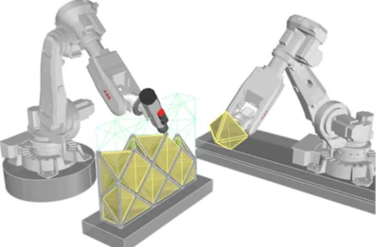
Secondly, the generalized printing takes place. One robot, in our case on a rail track, seeFig. 1, brings the blocks to their destination, and the other robot will extrude mortar on them. There is a layer by layer approach, one complete layer of blocks will be printed on, and so forth. The blocks act as a support for the extrusion, that therefore produces geometries unreachable by traditional printing.
Finally, in the context of confined masonry (seeSection 3), form-works for the reinforced concrete frame can be simultaneously printed, by the more classical printing approach.
The geometrical aspect of our principle is based on a space tessel-lation. The blocks are shaped like polyhedra, on the edges of which the mortar is printed (Fig. 2). Since they form a tessellation of the wall volume, their edges form a regular space truss. The final element is a structural and insulating wall. More precisely the edges of each block are carved, in our case by hot-wire cutting, so that they form a canal to receive the mortar. This process allows to manufacture a mortar space truss, a very efficient structure that promises great reduction of cement. It is important to note that “printable” mortar is crucial for the operation. Assembling all the insulating elements to pour self-con-solidating concrete inside would indeed create several difficulties. If we suppose that such a complex mould can be made, and be perfectly hermetic, it does not ensure that the concrete would fill the entire space. In addition, the foam mould would have to bear the liquid concrete hydrostatic pressure. This is one of the main drawbacks of such strategies. In our case, the mortar gains early age mechanical re-sistance, as described in [2], and can progressively work with the foam to withstand its own weight.
Conversely, thanks to the supporting action of the blocks, the rheological need for yield stress associated with the stacking of mortar laces in traditional concrete printing [11] is greatly reduced. Therefore the mortar final mechanical properties are less subject to reduction due to internal defaults, or “cold joints”. Furthermore, the blocks, once assembled, act as a confining element, which is one of the roles of traditional form-work, preventing the fresh mortar from drying and shrinkage.
3. Unreinforced confined masonry
Because it involves the assembly of blocks, stuck together by mortar, our system can be seen as a generalization of traditional breeze-blocks masonry. We consider here that our mortar is not reinforced, we discuss this possibility later. Without any rebar, the usual breeze-blocks and mortar system has to be restrained in a reinforced concrete frame. In that case, called confined masonry, the frame bears the main part of the imposed loads. The filling's mechanical role is to act as solid continuity, for bracing purpose. It also acts as a separating wall. From a purely
Fig. 1. Printing mortar while assembling blocks.
structural point of view, this system is quite inefficient. For a single house, and up to several levels building, the need in mechanical re-sistance of the filling, considering the concrete frame, is indeed very low. Up to a limit it could be said that in the traditional system the mortar alone brings the structural performance. With that in mind it is natural to organize the mortar distribution in a more efficient manner. In our system, the mortar forms a space truss, and the wall gets thermal insulation performances in addition.
In the following sections we examine several possible use cases. They are addressed with a parametric multi-objective study. We im-plement a geometry and examine it according to the following criteria: (a) overall weight, (b) mechanical resistance and (c) thermal con-ductivity.
We work on Grasshopper2, a plugin of the 3D modeller Rhinoceros
dedicated to parametric modelling. The structural analysis is performed with Karamba 3D3, a plugin embedded in Grasshopper dedicated to
linear elasticity calculation.
Since our mortar is printable, it has a very low granulometry and exhibits high compressive strength. It is coherent with the making of such light structures (the bar diameters can go down to 40 mm). The structural analysis shows that the maximum tensile stress is the critical value here, it stays true for bigger structures mentioned below. Considering unreinforced mortar, our normative context is confined masonry, governed by Eurocode 6, which does not specify a value for calculated maximum tensile stress. We choose to work with Eurocode 2 value ft =0.3fck2/3while taking additional security factors into account.
Our hypothesis for calculus is a C90/105 concrete, and since it is sup-posed to be non-reinforced mortar, we limit tensile stress to 3 MPa, which is a strongly conservative hypothesis in our case. The fragile behaviour of such a material accounts for those severe hypotheses. They are sufficient for exhibiting the interest of the approach (seeTable 2), yet a weaker material could probably be used. The thermal perfor-mances are calculated with a geometrical mean, taking into account a security factor corresponding to member thickness irregularities that can be expected at the nodes when extruding such a structure.
Each use case have a set of parameters and objectives to be eval-uated. The multi-objective optimization is conducted with Octopus4,
another plugin dedicated to heuristic methods.
4. Grid comparison
In order to evaluate the most adequate choice for the space tessel-lation, we use a parametric model of a truss wall supported on its perimeter. It compares to a single house traditional constrained ma-sonry wall, where the filling mainly acts as separation. Our model isolates the truss from other structural interactions to evaluate its sole capacity. The load cases are weight, horizontal wind pressure, and a third case corresponding to a solid choc (e.g. vandalism) in the middle of the wall. Given the possible lightness of the wall, it is indeed crucial to introduce such a verification, pointless for the traditional breeze-blocks system. This load case is inspired from hand-rails structural checking.
A 2.5 m height and 3 m width are fixed. The varying parameters are depth, bar diameters and tessellation size (opening). This last parameter is bounded by a maximum corresponding to the possibility of getting a 30 cm sphere through the bars. All the possibilities are compared in a three dimensional solution space, corresponding to the three following objectives: surfacic weight, thermal conductivity, and maximum tensile stress.
The parameters are then (1) the type of space truss grid (see next section), (2) the truss thickness and (3) the bars diameters. The
compared objectives are (a) additional insulation need (if needed, to reach target U-value of 0.09 W.m−2.K−1), (b) mechanical efficiency and (c) surfacic weight of the wall.
Different grid topologies are investigated for the concrete space truss in terms of structural efficiency and compatibility with the pro-posed manufacturing method. These topologies are taken from the edges of a space tessellation of the bounding box of the wall, so that a geometric duality with the polyhedral insulating blocks can be ob-tained. Considering that fresh mortar will be printed on the blocks, some geometrical configurations are to be avoided. We have retained five potential topologies, that does not present internal vertical mem-bers, that would be hard to print. They are listed inTable 1and shown onFig. 3.
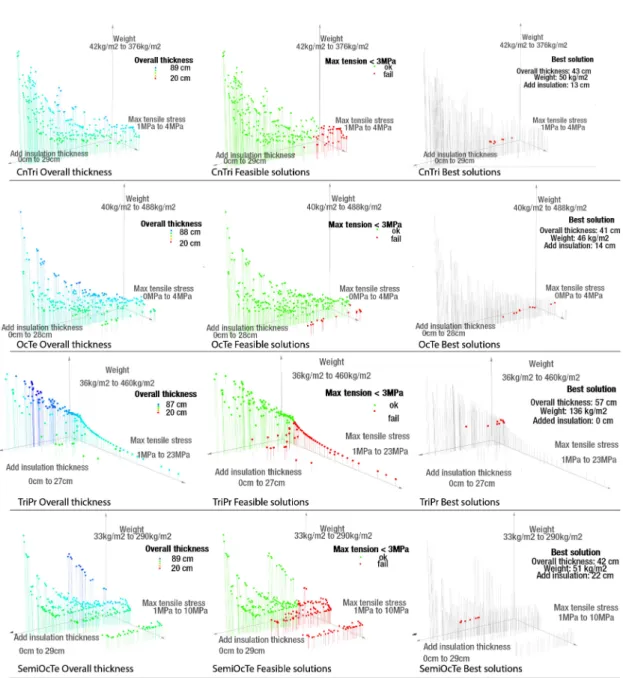
OnFig. 5are plotted the Pareto fronts of each topology, each point stands for a given set of parameters and all achieve Pareto optimality for the three objectives. Each of the four line of three graphs corre-sponds to a specific grid topology. The colors map additional in-formation, respectively the overall thickness of the wall (truss + addi-tional insulation), the solutions below the maximum tensile stress of 3 MPa, and the locations of the lightest of such acceptable individuals. The hexagonal pyramids solution would not allow an acceptable tensile stress for decent weight so the results are not plotted and the topology rejected.
OnFig. 4are plotted the weight variations with overall thickness for the ten best solutions of each configuration. The goal is to achieve the lightest and the thinnest structure in our context. We observe that the Triangle Prisms topology is the worst configuration. The three other solutions are of similar results for our criteria, therefore the best choice is the Semi Octahedra/Tetrahedra configuration that exhibits the lowest node valence, useful for fabrication purpose.
5. Cases studies
5.1. Single house separating wall
The model used for grid comparison shows that SemiOcte tessella-tion allows for good performances for the wall. Indeed it can work under the 3 MPa limit, while getting very strong insulation properties and for an overall thickness of 42 cm. We compare these results to the three following contemporary building systems for structural and in-sulating walls (Fig. 6).
i A traditional breeze block and mortar system, with 20 cm thick blocks (25 × 50), and 1 cm mortar joint. With a good insulator, like graphite polystyrene (λ = 0,031), a 20 cm layer is needed to reach target thermal performance.
ii A cellular concrete solution, 36 cm thick with 20 cm graphite polystyrene
iii A pre-wall system consisting in a insulating mould of one 5 cm and one 25 cm insulation layer connected with steel bars, for casting a 12 cm thick concrete wall. Minimum U value is of 0,15 W.m–2.K–1. The results inTable 2show that for equivalent performances our system greatly reduces overall weight, therefore material consumption.
Table 1
Grid types.
Grid name Description Maximum node valence
TriPr Triangle prisms 7
SemiOcTe Semi-Octahedra/Tetrahedra 8 OcTe Octahedra/Tetrahedra 9 CnTri Counter running triangle (tetrahedra) 10 Hexa Hexagonal pyramids 12
Fig. 3. Five grid topologies.
5.2. Single house shear wall and multi-storey loading
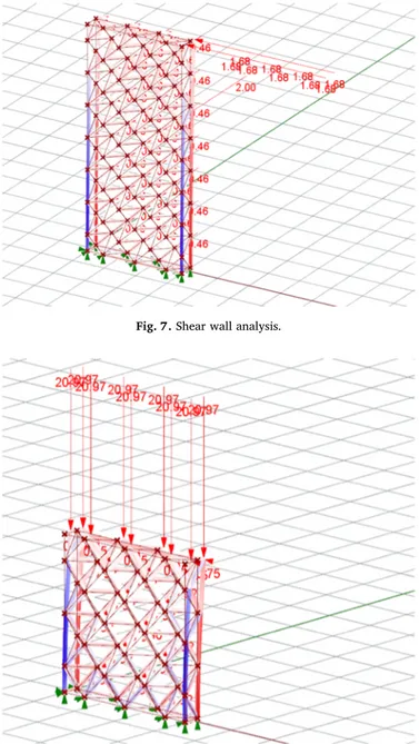
The interaction between filling and frame can be considered for the case of a shear wall. In that case, an in-plane horizontal load case is added to the model and the support conditions are limited to the base plane. The shear load is applied on top of the wall and corresponds to a wind pressure on an hypothetical perpendicular wall of same size. Height is added as varying parameter and maximized, width remains fixed. SeeFig. 7.
Analysis shows that the wall can withstand these conditions while keeping the tensile stress of the inside bars under 3 MPa. The frame bears the main part of the forces, that stay in a reasonable range. In that case the tensile stress limit allows a maximum height of 6 mm, and imposes the diameters to go up to 90 mm for an overall thickness of 45 cm. The surfacic weight of such a wall is around 100 kg.m–2.
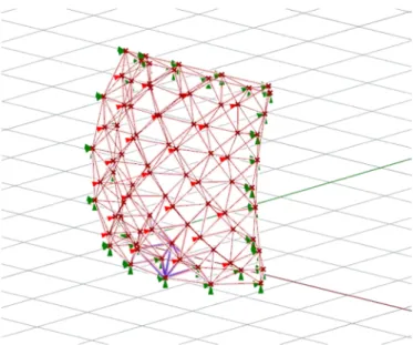
A similar approach can be used to check the possibility of bearing additional vertical loads, corresponding to a multi-storey building. The forces are again correctly transferred to the frame, which bears the main part of the compressive forces. SeeFig. 8.
6. Curved structures
Additive manufacturing is often mentioned as a mass customization approach, because it is intrinsically unconcerned by any economy of scale. Since there is no mould to cast into, repetitiveness of shape is irrelevant. Each piece can be uniquely shaped, for no additional cost. In that perspective, our approach, while being compared to existing methods with straight walls, can easily deal with curvature. The ar-chitectural interest is obvious, but there can also be a structural ad-vantage.
6.1. Curved separating wall
As an example we have applied a Moebius transformation to our separating wall, to give him some bump (seeFig. 9). The analysis is
Fig. 4. Ten best individuals weight/overall thickness.
Fig. 6. Single house separating wall. Table 2
Comparison with other systems.
Wall system Overall thickness Weight U-value
- cm kg ⋅m−2 W ⋅m−2⋅K−1
Breeze blocks 40 180 0.1
Cellular concrete 56 150 0.09
Pre-wall 42 220 0.15
Printed truss 42 50 0.09
Fig. 7. Shear wall analysis.
performed while taking curvature as an additional parameter. If the wall is convex, in relation to the horizontal loads, then the maximum tensile stress in the bars diminishes with the amount of curvature. This allows to consider curved wall for facade, with the aim of improving their mechanical efficiency.
6.2. Roofing
This opens perspectives to deal with more complex geometries, e.g. for roof design. Since our tessellation is made of regular polyhedra, the surfacic mesh it corresponds to is made of squares and regular triangles. This is not necessarily the case when curvature is added. However, the same tessellation process can be applied to a general surface mesh, given the fact that it is composed of sufficiently regular quadrangles, and that a regular offset can be done. Such meshes have fortunately been developed in Navier laboratory by R. Mesnil, who has im-plemented numerical geometry tools to generate conical and circular meshes [12]. They indeed exhibit strong regularity. In particular they are composed only of planar quadrangular facets, all beams intersect on a unique axis, and an offset of the mesh always exists, at a constant node distance. With such a mesh, it is easy to generate our
semi-Fig. 9. Curved wall analysis.
Fig. 10. Tessellation of a circular mesh.
octahedra / tetrahedra tessellation from a complex shell geometry, see
Fig. 10. Planarity of the quadrangles is also useful for roof covering.
7. Conclusion and perspectives
This building system generalizes both concrete printing and ma-sonry. Indeed, the use of polyhedral supports for the extrusion allows the making of very light concrete structures, that would not be feasible in a classical printing approach. Moreover, the blocks/mortar system, broadly used in today's construction is also elevated to complex geo-metry. This complexity may seem paradoxical, given the fact that this traditional building system was designed for humans. The blocks are sized to be handled by men, and the parallelepipedic shape eases the process in terms of required precision and versatility. In a context of automated construction, one can truly make use of geometrical com-plexity, and very good precision of handling. The versatility of the system is also increased in the sense that each case can be treated specifically with very few additional cost.
In this paper, the interest of such a system for today's construction has been shown. Prototypes are currently being made in Navier Laboratory, and the first results are quite encouraging. OnFig. 11is a picture of a meter high mortar truss inside polystyrene blocks. Some of the blocks have been carved to exhibit the internal structure. The blocks were made in 5 h of hot wire cutting, and the extrusion lasted 40 min. The blocks were placed by hand, the automation of this part will be addressed in a second phase. The extrusion step is currently studied to perfect the result in terms of homogeneity and overall quality of the bars.
With the roofing design, it becomes quite difficult to keep the mortar unreinforced, or the reinforced frame would need a very parti-cular design. Some reinforcement can very possibly be added though, even if such strategies still miss full development today. Three main approaches can be considered. First, the mortar could be embedded with steel fiber, as for UHPFC. This raises numerous concerns, espe-cially about the possibility of pumping such a mixture, but also about the correct impregnation of the fibers in the paste, as well as their or-ientation.
Another possibility is to make the insulating blocks themselves with a steel bar stuck to it. The printing method would have to ensure a correct coating of the rebars. Special attention would have to be given to the nodes design, so that tensile forces could be transferred from one bar to another.
The third possible approach, already experimented by some teams today, including ours, is to print the mortar with continuous fibers, to
create a composite material. Again, impregnation is crucial so that the final material behaves as planned, which raises some technological problems. As for now, the present approach generalizing mortar printing can be applied to unreinforced masonry, and provides novel performances.
Acknowledgments
The authors would like to thank V. Esnault at LafargeHolcim Research and Development for fruitful discussions. Support from LafargeHolcim is gratefully acknowledged.
References
[1] Pegna J. Exploratory investigation of solid freeform construction. Autom. Constr. 092658051997;5(5):427–37: http://www.sciencedirect.com/science/article/pii/ S0926580596001665https://doi.org/10.1016/S0926-5805(96)00166-5. [2] Gosselin C, Duballet R, Roux P, Gaudillière N, Dirrenberger J, Morel P.
Large-scale 3D printing of ultra-high performance concrete - a new processing route for architects and builders. Mater. Des. 2016;100:102–9: http://www.sciencedirect. com/science/article/pii/S0264127516303811.
[3] Khoshnevis B. Automated construction by contour crafting - related robotics and information technologies. Autom. Constr. 092658052004;13(1):5–19.https://doi. org/10.1016/j.autcon.2003.08.012.
[4] Lim S, Buswell R, Le T, Wackrow R, Austin S, Gibb A, et al. Development of a viable concrete printing process. Proceedings of the 28th International Symposium on Automation and Robotics in Construction (ISARC2011) 2011. p. 665–70.https:// doi.org/10.1080/0042311YYxxxxxxxx. (January).
[5] Lim S, Buswell R A, Le T T, Austin S A, Gibb A G F, Thorpe T. Developments in construction-scale additive manufacturing processes. Autom. Constr.
092658052012;21(1):262–8.https://doi.org/10.1016/j.autcon.2011.06.010. [6] Le T T, Austin S A, Lim S, Buswell R A, Gibb A, Thorpe T. Mix design and fresh
properties for high-performance printing concrete. Mater. Struct. 1359-59972012;45:1221–32.https://doi.org/10.1617/s11527-012-9828-z. [7] Le T T, Austin S A, Lim S, Buswell R A, Law R, Gibb A G F, et al. Hardened
properties of high-performance printing concrete. Ceme. Concr. Res.
000888462012;42(3):558–66.https://doi.org/10.1016/j.cemconres.2011.12.003. [8] Feng P, Meng X, Zhang H. Mechanical behavior of FRP sheets reinforced 3D
elements printed with cementitious materials. Compos. Struct.
026382232015;134:331–42.https://doi.org/10.1016/j.compstruct.2015.08.079. [9] Bosscher P, Williams R L, Bryson L S, CastLacouture D. Cable-suspended
ro-botic contour crafting system. Autom. Constr. 092658052007;17(1):45–55.https:// doi.org/10.1016/j.autcon.2007.02.011.
[10] Duballet R, Baverel O, Dirrenberger J. Classification of building systems for concrete 3D printing. Autom. Constr. 092658052017;83(July):247–58.https://doi. org/10.1016/j.autcon.2017.08.018.
[11] Roussel N. Rheological requirements for printable concretes. Cem. Concr. Res. 000888462018;112(January):76–85.https://doi.org/10.1016/j.cemconres.2018. 04.005.
[12] Mesnil R, Douthe C, Baverel O, Léger B. Generalised cyclidic nets for shape modelling in architecture. Int. J. Archit. Comput. 204839882017;15(2):148–68.