Science Arts & Métiers (SAM)
is an open access repository that collects the work of Arts et Métiers Institute of Technology researchers and makes it freely available over the web where possible.
This is an author-deposited version published in: https://sam.ensam.eu
Handle ID: .http://hdl.handle.net/10985/10020
To cite this version :
Yves CHEMISKY, George CHATZIGEORGIOU, Kumar PARIKSHITH, Dimitris LAGOUDAS - A constitutive model for cyclic actuation of high-temperature shape memory alloys - Mechanics of Materials - Vol. 68, p.120-136 - 2014
Any correspondence concerning this service should be sent to the repository Administrator : [email protected]
Science Arts & Métiers (SAM)
is an open access repository that collects the work of Arts et Métiers ParisTech researchers and makes it freely available over the web where possible.
This is an author-deposited version published in: http://sam.ensam.eu
Handle ID: .http://hdl.handle.net/null
To cite this version :
Yves CHEMISKY - A constitutive model for cyclic actuation of high-temperature shape memory alloys - A constitutive model for cyclic actuation of high-temperature shape memory alloys - Vol. 68, p.120-136 - 2014
Any correspondence concerning this service should be sent to the repository Administrator : [email protected]
A Constitutive Model for Cyclic Actuation of High-Temperature
Shape Memory Alloys
Yves Chemiskya, George Chatzigeorgioub, Parikshith Kumarc, Dimitris C. Lagoudasc,⇤
aArts et M´etiers ParisTech Metz, LEM3 UMR CNRS 7239, Metz, France
bChair of Applied Mechanics, Friedrich-Alexander Universit¨at Erlangen-N¨urnberg, Egerlandstrasse 5,
91058 Erlangen, Germany
cDept. of Aerospace Engineering, Texas A&M University, 3409 TAMU College Station, TX 77843-3409,
USA
Abstract
In this work, a three dimensional constitutive model for High Temperature Shape Memory Alloys (HTSMAs) is presented. To describe the evolution of the cyclic actuation behavior of such alloys, viscoplastic mechanisms and transformation induced plasticity are introduced in addition to the classical transformation behavior of Shape Memory Alloys. Based on contin-uum thermodynamics, the evolution of phase transformation, plasticity induced transforma-tion, retained martensite and viscoplasticity are described. Deformation mechanisms that occur over the operational range of such HTSMAs have been identified from the thermome-chanical behavior of a NiTiPd alloy. The proposed model has therefore been validated based on the prediction of the thermomechanical behavior of the studied NiTiPd HTSMA alloy under di↵erent loading conditions. Careful attention is devoted to the calibration procedure to identify the contribution of the di↵erent mechanisms independently. Finite element anal-ysis (FEA) is performed to demonstrate the capabilities of the model to describe the cyclic behavior of HTSMA devices.
Keywords: Shape memory alloys, HTSMAs, viscoplasticity, martensitic phase transformation, cyclic actuation
⇤Corresponding author.
Email address: [email protected] (Dimitris C. Lagoudas)
1. Introduction
Shape Memory Alloys (SMAs) have been investigated for engineering applications since
the later half of the 20th century due to their ability to recover substantial deformation.
Among other unique behaviors, their high recoverable strains and associated actuation work density have made them prominent for the design of actuators for the aerospace, petroleum and biomedical industries (Otsuka and Wayman, 1999; Lagoudas, 2008). Driven by indus-trial applications, especially aerospace and oil industries that demand actuation at high operational temperatures (DeCastro et al., 2005; Andersen and Sangesland, 1999), a new class of alloys, referred to as High Temperature Shape Memory Alloys (HTSMAs) have been developed (Wu and Wayman, 1987; Lidquist and Wayman, 1990; Pu et al., 1995; Thoma and Boehm, 1999; Kockar et al., 2006; Ma et al., 2010). These alloys can operate at temper-atures higher than 100 C, which make them an attractive alternative to legacy electrical or hydraulic actuators.
Among the di↵erent alloys that exhibit martensitic transformation above 100 C, NiTiPd HTSMAs have been investigated for their actuation capabilities at temperatures ranging from 200-500 C and stress levels greater than 100 MPa (Lidquist and Wayman, 1990; Lindquist, 1988; Golberg et al., 1994, 1995b,a; Lindquist, 1988; Noebe et al., 2006; Padula II et al., 2006; Cai et al., 2000). At these operational conditions, constant stress thermal cycles lead to the appearance of irrecoverable rate independent and rate dependent strains, which a↵ect the actuation performance. As a consequence, these materials are suitable for applications that requires limited actuation cycles. To develop a design tool adapted to HTSMA actua-tors, a constitutive model that considers the e↵ects related to the phase transformation and viscoplasticity is necessary to predict the evolution of irrecoverable strains during cyclic ac-tuation. This paper is focused on the development of such a constitutive model for HTSMAs based on a thermodynamic framework. Particular attention is devoted to the prediction of actuation capability and the appearance of irrecoverable strains during cyclic loading.
During the last thirty years significant e↵orts have been conducted on developing consti-tutive models for regular SMAs (Tanaka et al., 1986; Liang and Rogers, 1990; Brinson, 1993; Boyd and Lagoudas, 1996; Leclercq and Lexcellent, 1996; Savi et al., 2002). These models were incrementally improved over the last ten years and implemented in Finite Element
Analysis (FEA) packages (Qidwai and Lagoudas, 2000; Panico and Brinson, 2007; Lagoudas et al., 2012; Chemisky et al., 2011; Sedlak et al., 2012). All these models describe the behav-ior of conventional SMAs and, since the operating temperatures and maximum stress levels are relatively low, no influence of irrecoverable strains due to creep or high stress e↵ects have been taken into account. The evolution of transformation induced plasticity has been further considered for conventional SMAs by Bo and Lagoudas (1999b) and Lagoudas and Entchev (2004b) to account for the appearance of irrecoverable strains upon cycling. The coupling between phase transformation and plasticity has been considered in the literature for the simulation of shape memory alloys that operates a low temperatures (compared to their melting temperatures), but where the stress level can reach the plastic yield stress (Hartl and Lagoudas, 2009; Zaki et al., 2010; Khalil et al., 2012). A one dimensional model ac-counting for the coupling between phase transformation and viscoplasticity has been recently developed by Lagoudas et al. (2009) for the simulation of HTSMAs, where viscoplastic creep is observed. A three-dimensional extension of this model was developed and implemented in a FEA software by Hartl et al. (2010b). The model focused on the unique behavior ex-hibited when phase transformation and viscoplasticity are occurring simultaneously, however the cyclic evolution of this behavior was not considered. The proposed model thus focuses on the appearance of irrecoverable transformation-induced rate-independent plasticity (TRIP), the accumulation of retained martensitic phase and viscoplastic strains for multiple cycle thermomechanical loading.
The determination of the deformation mechanisms that occur over the operational range of stress level and temperature has been carried out via the experimental characterization
of a T i50.5P d30N i19.5 HTSMA, conducted for di↵erent loading conditions (loading path,
loading rate, temperature) (Kumar et al., 2011). Additional tests have been conducted and presented in this paper, to properly isolate and identify specific mechanisms such as the evolution of retained martensite and plasticity during transformation. Also, creep test have been conducted to properly identify the viscoplastic behavior of the alloy.
Based on the experimental observation of deformation mechanisms, a thermodynam-ical constitutive model is proposed, with several unique features: i) an adapted law for the evolution of transformation-induced plasticity; ii) the description of the evolution of
retained martensite and iii) the description of simultaneous transformation/viscoplastic be-havior based on a viscoplastic law accounting for cyclic evolution of primary and secondary creep. The implementation of a viscoplastic power law including hardening e↵ects (Lemaitre and Chaboche, 2002) allows for the simulation of such behavior. The introduction of a vol-ume fraction of retained martensite is motivated by the experimental evidence of the presence
of a martensitic phase in NiTiPd systems at high temperature above Af (Af + 100 C)
(Ku-mar and Lagoudas, 2010). It has been observed that retained (Ku-martensite is pinned by the accumulation of plastic strains generated during transformation.
The calibration of the proposed model is based on the experimental characterization of
the T i50.5P d30N i19.5HTSMA. The viscoplastic behavior is calibrated from creep and uniaxial
tests conducted at di↵erent stress-temperature conditions. The model parameters related to rate-independent mechanisms are calibrated based on constant stress thermal cycles. To validate the model, the prediction of the actuation response of HTSMAs under di↵erent conditions are compared with additional cyclic actuation tests.
The work is organized as follows: Section 2 describes some of the earlier tests along with additional thermomechanical characterization of the investigated NiTiPd HTSMA, with uniaxial isothermal compression tests, isobaric thermal actuation cycles at di↵erent heat-ing/cooling rates with and without creep. The unique response of this HTSMA is analyzed in this section to motivate the definition of a 3-D constitutive model, based on continuum thermodynamics, presented in section 3. Section 4.1 presents the calibration procedure of the proposed model. The final section presents the comparison of the model with a set
of experiments performed on a N iT iP d30 HTSMA, from the calibration experiments to a
designated set of validation experiments, to discuss the prediction capabilities of the model. Finally, numerical examples are presented, that include the thermomechanical response of complex structures undergoing multiple actuation cycles. The conclusions of this work are summarized in the last section.
2. Material Selection and Experimental Characterization
From an array of NiTiX (X=Pd, Pt, Hf, Zr or Au) HTSMAs available presently, NiTiPd based systems have shown good actuation characteristics at operational temperatures higher
than NiTiHf or NiTiZr based systems (Lidquist and Wayman, 1990; Lindquist, 1988; Golberg
et al., 1994, 1995b,a). For the present work, the T i50.5P d30N i19.5 composition is chosen
because this particular composition has been widely investigated in the literature (Noebe et al., 2006; Padula II et al., 2006; Cai et al., 2000). The transformation temperatures for this composition lies between 200 C and 300 C (0.3-0.35 of the absolute melting temperature), which is at the lower end of the creep regime (typically 0.3-0.5 of the absolute melting temperature) and the transformation strain is around 3.0% (Golberg et al., 1994, 1995b,a). However, with the application of a load, it is necessary to heat the SMA to temperatures higher than the no-load transformation temperatures to ensure full actuation. Under such operating conditions both creep and the phase transformation can occur simultaneously and thus impact actuator performance (Kumar and Lagoudas, 2010; Lagoudas et al., 2009).
A hot worked T i50.5P d30N i19.5 HTSMA bar was fabricated from which cylindrical
spec-imens (7 mm diameter and 14 mm height) were machined for uniaxial thermomechanical tests. A custom high temperature thermomechanical test setup was utilized for the testing of the HTSMA specimens. The force, strain, temperature and time were monitored through-out the duration of the test. Further details of the alloy fabrication, specimen machining and thermomechanical tests setup are described in Kumar et al. (2011). To determine the trans-formation temperatures of the alloy, a preliminary thermal cycle was conducted at 10 C/min on a specimen under a no-load condition. The transformation temperatures were determined by the tangent intersection method and test temperatures for the uniaxial, creep and the load-bias thermal cycling tests were determined from those results.
To determine the parameters that would assist with the development of the combined phase transformation, plasticity and visco-plastic model, the experiments conducted were organized in three groups to study the thermoelastic behavior, the visco-plastic behavior and the phase transformation behavior, respectively. The tests for the thermoelastic behavior and the creep experiments for the viscoplastic behavior are described in elaborate detail in Kumar et al. (2011) and therefore will not be discussed in this work. The additional tests for the viscoplastic behavior as well as the phase transformation are described in this section and their results will be presented and discussed.
-1000 -900 -800 -700 -600 -500 -400 -300 -200 -100 0 -16 -14 -12 -10 -8 -6 -4 -2 0 Str es s (MPa ) Strain (%) 400°C 500°C
Figure 1: Uniaxial tests conducted at 400 and 500 C at a loading rate of 10 4/sec.
2.1. Creep Tests
To study the viscoplastic material behavior, standard creep tests were conducted at stress levels of 100, 300, and 500 MPa and at temperatures of 300 C, 400 C, and 500 C to cover the entire operational range of the considered HTSMA. The results from these tests are described in Kumar et al. (2011). To understand the viscoplastic hardening behavior of the HTSMA, in addition to the creep tests two additional uniaxial tests were conducted at
400 C and 500 C at a loading strain rate of 10 4/sec. The results from the uniaxial tests
at both 400 C and 500 C are shown in Fig. 1. From the uniaxial results it is observed that the hardening behavior in the specimen decreases with increasing test temperature. This softening, and the drop in the yield stress level with the increase in the test temperature from 400 C to 500 C suggests that the plastic and viscoplastic deformations are dominant. Due to the constant strain rate of loading, the uniaxial tests provide calibration data for transient primary and secondary creep.
-16 -14 -12 -10 -8 -6 -4 -2 0 0 100 200 300 400 500 600 Strain (%) Temperature (°C) Initial loading 400 MPa A B C D E F G 20°C/min (a) -20 -18 -16 -14 -12 -10 -8 -6 -4 -2 0 0 100 200 300 400 500 600 Strain (%) Temperature (°C) Initial loading 20°C/min 500 MPa (b)
Figure 2: Load-bias thermal cycling tests at 20 C/min conducted at a stress of (a) 400 MPa and; (b) 500 MPa. Simultaneous creep and phase transformation occurs during the reverse phase transformation.
2.2. Load-Biased Thermal Cycling Tests
To determine the transformation regions for the stress-temperature phase diagram as well as to understand the evolution of the simultaneous creep and transformation behavior, constant stress thermal cycling tests (referred to as load-bias tests) were conducted at applied compressive stress levels of 400 and 500 MPa. The upper and lower limits for the thermal cycling were fixed at 100 C and 500 C, to ensure complete transformation at the highest stress level (500 MPa) and to have a consistent thermomechanical history across all thermally cycled specimens. Each specimen was heated to 500 C under no-load condition and then
loaded to the desired stress at a strain rate of 10 2/sec, in the austenitic state. From this
stage, three consecutive thermal cycles were conducted at 20 C/min and 5 C/min by cooling the specimen down to 100 C and subsequently heating the specimen to a temperature of 500 C. The results from the thermal cycling at the two stress levels, 400 MPa and 500 MPa, are shown in Fig. 2a and Fig. 2b.
From Fig. 2, the non-linear evolution of the deformation after the initial loading at both 400 and 500 MPa indicates that the material creeps in the austenitic state, between 450 C
and 500 C. Below 450 C, a linear thermal contraction until the point B is observed. As the specimen is cooled in the austenitic state, the creep rate and consequently the influence of creep decreases as the temperature reduces during the thermal cycling. At point B, forward transformation initiates and the material undergoes transformation into martensite (point C). Upon heating, the reverse transformation begins at E and the strain recovery initiates. As the temperature is increased to point F, the creep rate in the material exceeds the rate of strain recovery resulting in an inflection and subsequent loss of actuation strain. The thermal cycle also results in the generation of rate independent residual strains which are a combination of plastic strain generated over the course of transformation as well as retained martensite. In subsequent cycles a similar behavior is observed, however, with a reduced amount of transformation, plastic and viscoplastic strains. This decrease in the inelastic strains is associated with the plastic and viscoplastic hardening behavior of the material. The material also exhibits larger viscoplastic strain after martensitic phase transformation (upon heating, F to G) than the amount observed during the subsequent cooling.
The evolution of the strains due to TRIP e↵ect and the additional e↵ect of retained martensite need to be better understand to develop a constitutive model that will capture such e↵ects. While it is understood that this residual strain (a combination of the TRIP and retained martensite) occurs in each cycle, it still remains unclear if this strain is in fact (i) solely developed during forward transformation, (ii) during the reverse transformation or (iii) distributed between the two in a specific ratio. Thermal cycling tests were conducted with di↵erent thermomechanical loading path to better understand the evolution of such residual strains. The maximum test temperature for every test was fixed at 370 C for this alloy, to avoid viscoplastic strain contributions. In the first test (shown in Fig. 3a), a specimen is subjected to the following thermomechanical loading path:
1. Heating from room temperature (A) to 370 C (B) under a constant compressive stress of 2 MPa
2. Loading to a stress level of 400 MPa (at 370 C) (C)
3. The stress is kept constant (400 MPa) and the specimen is cooled to 100 C (D) at a cooling rate of 20 C/min
-9 -8 -7 -6 -5 -4 -3 -2 -1 0 0 100 200 300 400 500 Str ai n (% ) Temperature (°C)
Half cycle at 400 MPa
Heating to 370 C at 2 MPa loading 2.5% A" C" D" E" F" B" hea+ng" (a) -9 -8 -7 -6 -5 -4 -3 -2 -1 0 0 100 200 300 400 500 Str ai n (% ) Temperature (°C) !"##$%&%#'$()$*++$,-($ loading 3.7% A" C" D" E" F" B" hea+ng" (b)
Figure 3: Strain-temperature diagram showing the residual strain generated in the material upon (a) cooling the material from austenite to martensite under load - unloading - heating to austenite under no load; (b) cooling the material from austenite to martensite and subsequently heating it back to austenite under load - unloading.
5. Heating to 370 C (F) at a heating rate of 20 C/min (s)
A relative compression (⇠2.5%) of the specimen is measured between the end of step 1
and the end of step 5. This strain represents the residual strain generated in the half thermal cycle, since no additional strain beside thermal expansion is generated during the heating at 2 MPa. Indeed, it has been shown that a full thermal cycle under this stress level does not exhibit any irrecoverable strain (Kumar et al., 2011).
For the second test (Fig. 3b), a specimen is subjected to the following thermomechanical cycle:
1. Heating from room temperature (A) to 370 C (B) under a constant compressive stress of 2 MPa
2. Loading to a stress level of 400 MPa (at 370 C) (C)
3. The stress is kept constant (400 MPa) and the specimen is cooled to 100 C (D) at a cooling rate of 20 C/min (s)
4. Heating to 370 C (E) at a heating rate of 20 C/min (s) 9
5. Unloading to a stress level of 2 MPa (at 370 C) (F)
A relative compression (⇠3.7%) of the specimen is measured between the end of step 1
and the end of step 5, and represents the the total strain generated in the complete thermal cycle. By comparing the strain generated from the first test and the second test, it is observed that two thirds of the residual strain is generated during the forward transformation and one third is generated during the reverse transformation. The additional tests conducted are utilized to characterize the material behavior at high temperature under high stress level, where large viscoplastic strain, TRIP strains and strain due to retained martensite are exhibited. These tests are unavoidable to determine the evolution of such strains under such thermomechanical conditions. A complete list of all the di↵erent tests conducted in the experimental section that are utilized for the characterization of the selected HTSMA alloy is summarized in the following Table 1.
Table 1: List of tests conducted for the calibration of the HTSMA model
Test # Test type Test details Source
1 Thermal cycling 0 MPa, 10 C/min Kumar et al. (2011)
2-3 Uniaxial loading 185 C and 295 C, at 10 4/sec Kumar et al. (2011)
4-6 Creep tests 100, 300 and 500 MPa at 300 C Kumar et al. (2011)
7-9 Creep tests 100, 300 and 500 MPa at 400 C Kumar et al. (2011)
10-12 Creep tests 100, 300 and 500 MPa at 500 C Kumar et al. (2011)
13-14 Uniaxial loading 400 and 500 C, at 10 4/sec Figure 1
15-16 Thermal cycling 400 and 500 MPa at 20 C/min Figure 2
17-18 Thermal cycling Half cycle and a complete cycle at 400 MPa Figure 3
3. 3-D Thermomechanical Model for Cyclic Response of HTSMAs
The proposed thermomechanical model is based on the framework of simultaneous creep and transformation models, initiated by Lagoudas et al. (2009) in 1-D, and extended in 3-D by Hartl et al. (2010b). The derivation of the proposed model is based on an internal state variables approach and begins with the description of a free energy potential. In order to
capture the mechanisms observed in the thermal cyclic tests of Fig. 2, the proposed free energy potential needs to include the e↵ects of i) the martensitic phase transformation, ii) the transformation-induced, rate independent plasticity (denoted here as TRIP) and iii) the rate-dependent plasticity. A Gibbs free energy is expressed as a function of the
external state variables (applied stress tensor and absolute temperature T ), and a set
of internal state variables ⇣ representative of the internal state of the considered system. The phase transformation mechanism is assumed to be described by the following set of
internal variables: the martensitic volume fraction ⇠, the transformation strain tensor "t
and the transformation hardening energy gt. Transformation induced plasticity requires the
inclusion of the transformation-induced plastic strain tensor "tp as an additional internal
state variable. To describe the viscoplastic e↵ects, the viscoplastic strain tensor "vp, the
accumulated viscoplastic strain p and the viscoplastic hardening energy gvp, which is essential
for the description of the hardening behavior of the HTSMA at 400 and 500 C (Fig. 1b), are introduced in the internal state variables set. The Gibbs free energy is decomposed into three contributions and written as:
G( , T, ⇣) = (1 ⇠)GA
te( , T ) + ⇠GMte( , T )
+Gmix( , T, ⇣),
(3.1)
where GA
te and GMte represent the thermoelastic energy terms of austenite and martensite,
respectively, while Gmix is the mixing energy term. The thermoelastic Gibbs free energy of
each phases is:
Gte( , T ) = 1 2⇢ : SSS 1 ⇢ : ↵↵↵(T T0) + c (T T0) T ln ✓ T T0 ◆ s0T + u0, = A, M, (3.2)
while the mixing energy term contains the contribution of the di↵erent inelastic strain mech-anisms: Gmix( , T, ⇣) = 1 ⇢ : (""" t+ """tp) + 1 ⇢g t 1 ⇢ : """ vp+1 ⇢g vp. (3.3)
Assuming the additive decomposition of the thermoelastic components of austenite and
martensite, the elastic compliance tensorS, the specific entropy s0 and the specific internal
energy u0 of the two-phase material are defined by the rule of mixtures: SSS = SSSA+⇠(SSSM SSSA).
The density ⇢, the thermal expansion tensor ↵↵↵ and the specific heat c are assumed to be the
same for both phases. T0 denotes a reference temperature at which the thermal expansion
strain is set to be zero. Combining the first and second law of thermodynamics, the strong
form of the second law is written as1
⇢ ˙G ˙ : """ ⇢s ˙T 0. (3.4)
Using the forms employed by Lagoudas and Entchev (2004a), both the rate of transforma-tion strain and the rate of TRIP strain are assumed to be proportransforma-tional to the rate of the martensitic volume fraction ˙⇠:
˙"t= ⇤t˙⇠, ˙"tp = ⇤tp˙⇠ (3.5)
where ⇤t is the transformation direction tensor and ⇤tp is the TRIP direction tensor. The
transformation strain direction strain tensor ⇤t is given as:
⇤t= 8 < : ⇤tf wd, ˙⇠ > 0, ⇤trev, ˙⇠ < 0, (3.6) where ⇤t
f wd is the transformation direction tensor during the forward transformation and
⇤t
rev is transformation direction tensor during the reverse. The form of these tensors are
defined as (cf. Bo and Lagoudas (1999a) and Lagoudas and Bo (1999))
⇤tf wd = 3 2H cur 0, ⇤t rev = "t r ⇠r . (3.7)
In the above, 0 is the deviatoric part of the stress tensor, ¯ = p3/2 0 : 0 is the von
Mises equivalent stress, Hcur = Hcur(¯) is the transformation strain magnitude, """t r is the
transformation strain at the transformation reversal and ⇠ris the martensitic volume fraction
at the transformation reversal.
Fig. 2 indicates that the transformation strain magnitude of the examined HTSMA material depends on the applied stress. Lagoudas and Bo (1999) introduced a dependency of the transformation strain magnitude as a function of the stress magnitude. In this work,
we utilize the empirically motivated exponential evolution of Hcur of Hartl et al. (2010a):
Hcur( ) = 8 > < > : Hmin, < crit
Hmin+ (Hsat Hmin)(1 e k( crit)), >
crit
(3.8)
In this equation, Hmin represents the observed uniaxial transformation strain at zero stress
level, and Hsat corresponds to the maximum transformation strain for a uniaxial loading
at sufficiently high stress level. crit is the critical von Mises equivalent stress below which
Hcur = Hmin. The parameter k is used for the calibration of the evolution of Hcur from
Hmin to Hsat for the applied stress levels above
crit.
The TRIP strain is assumed to be dependent on the the history of the martensitic phase transformation, precisely the evolution of stress-oriented detwinned martensite volume frac-tion (Bo and Lagoudas (1999b)). The detwinned volume fracfrac-tion can be defined as:
⇠d= H
cur
Hsat⇠ (3.9)
To describe the cyclic evolution of the plastic strain, the accumulated detwinned marten-site volume fraction is defined by Bo and Lagoudas (1999b) as:
⇣d=
Z t
0
| ˙⇠d(⌧ )|d⌧ (3.10)
The form of TRIP direction tensor is assumed to be dependent on this accumulated de-twinned martensite volume fraction, and the following form is proposed, motivated by the work of Lagoudas and Entchev (2004a):
˙"tp = ⇤tp˙⇠, ⇤tp= 8 < : ⇤tpf wd, ˙⇠ > 0, ⇤tprev, ˙⇠ < 0. (3.11)
⇤tprev the form during the reverse. These two tensors are defined as ⇤tpf wd = 3 2 0 ¯w1 ⇣ C0tp+ C1tp e ⇣ d/Ctp 2 ⌘ H cur Hsat, ⇤tprev = """ t r ¯ "t r(1 w1) ⇣ C0tp+ C1tp e ⇣d/C2tp⌘ H cur Hsat. (3.12)
In equation (3.12), C0tp = C0tp(¯) and C1tp = C1tp(¯) are stress dependent functions and C2tp
is a constant model parameter. The parameter w1, which is motivated by the experimental
curves of Fig. 3, describes the ratio of the TRIP strain that is generated during forward
transformation according to the TRIP strain generated for a full cycle. The functions C1tpand
C2tpdescribe the exponential evolution of the TRIP strains at the first cycles, until the
steady-state evolution is reached, as proposed by Lagoudas and Entchev (2004a). Additionally, the proposed evolution law (3.12) is based on the assumption that the TRIP strain in HTSMAs does not have a saturation value. Instead, after several cycles, it evolves linearly with the
accumulated detwinned martensitic volume fraction. C0tp describes this linear evolution of
the TRIP strain for each cycle, which corresponds to a steady-state ratcheting e↵ect. The proposed model also considers the e↵ect of the retained martensite that does not
transform back into austenite at the conventional martensite ! austenite transformation
stress/temperature state. This volume of martensite is pinned due to the appearance of plastic deformation during martensitic transformation, as observed experimentally by Kumar
and Lagoudas (2010) in N iT iP d40 HTSMAs. Thus, the transformation strain associated
with this volume fraction of retained martensite can not be recovered upon heating. The following evolution equation for the volume fraction of retained martensite, similar to the evolution equation of TRIP strain is proposed:
˙⇠R= 8 > > < > > : w2C1R e ⇣ d/CR 2 ˙⇣d, ˙⇠ > 0, (1 w2)C1R e ⇣ d/CR 2 ˙⇣d, ˙⇠ < 0. (3.13) In equation (3.13), CR
1 = C1R(¯) is a stress dependent function and C2R is a constant model
parameter. Due to experimental observations (Fig. 3), the parameter w2 is required in
order to describe the di↵erent evolution of retained martensite between forward and reverse transformation.
The final variable related to the phase transformation, the transformation hardening
energy gt, is given by an evolution equation of the form, motivated by Lagoudas (2008),
which in the proposed form includes the e↵ect of retained martensite:
˙gt = ft˙⇠, ft = 8 < : ff wdt , ˙⇠ > 0, frevt , ˙⇠ < 0, (3.14) where ff wdt (⇠) = 1 2a1(1 + ⇠ n1 (1 ⇠)n1 ) + a3, (3.15) ft rev(⇠) = 1 2a2(1 + ⇠ n2 (1 ⇠)n2) a 3. (3.16)
In the above relations, a1,a2, a3, n1 and n2 are material parameters. Note that when a
full thermomechanical cycle is considered, the martensitic volume fraction ⇠ varies from the
current value of ⇠R to 1.
Considering the viscoplastic mechanism, it is assumed that an equivalent accumulated plastic strain, p, and the viscoplastic hardening energy will be used as internal variables. The following evolution law of the viscoplastic hardening energy is assumed:
˙gvp = fvp ˙p, (3.17)
where fvp is a scalar function of p of the form (Lemaitre and Chaboche, 2002)
fvp = Q1 p + Q2 1 e Q3 p , (3.18)
and Q1 = Q1(T ), Q2 = Q2(T ) and Q3 = Q3(T ) are temperature dependent model
pa-rameters. Note that the exponential term of this hardening function is characteristic of
the so-called primary creep mechanism, while the linear term Q1 p is characteristic of the
viscoplastic hardening.
It is further assumed that the viscoplastic strain rate ˙"vp and the rate of the equivalent
accumulated viscoplastic strain rate ˙p are related through the following evolution equa-tion (Lemaitre and Chaboche, 2002):
˙"""vp = ⇤⇤⇤vp˙p, ⇤⇤⇤vp = 3 2
0
¯, (3.19)
where ⇤vp is the viscoplastic direction tensor.
With regard to the rate dependent viscoplastic mechanism, we identify an appropriate evolution equation for the rate of the equivalent viscoplastic strain p of the form (Lemaitre
and Chaboche, 2002)2 ˙p = ⌧ ¯ fvp Yvp Ka Na , (3.20)
where Yvp = Yvp(T ) is the temperature dependent elastic limit after which creep occurs,
Ka= Ka(T ) is the “drag stress” and Na = Na(T ) is the “stress exponent”. Both are assumed
to be temperature-dependent model parameters.
To model the di↵erence observed between the viscoplastic strain rates at the end of the reverse transformation and before the beginning of the forward transformation in the subsequent cycle, it is assumed that each time the material reaches the martensitic phase, the primary creep part of the viscoplastic strain is re-initialized. Specifically, when the material is in the martensitic state, the viscoplastic strain that corresponds to primary creep is removed from the total accumulated viscoplastic strain p in the expression of the viscoplastic hardening function (3.18).
Taking into account the proposed evolution equations, the second law of thermodynamics leads to
⇥
: (⇤⇤⇤t+ ⇤⇤⇤tp) ⇢@⇠G ft⇤ ˙⇠ + ( : ⇤vp fvp) ˙p 0. (3.21)
A last assumption of the model is to assume that transformation and viscoplasticity are independent and both strongly dissipative. This assumption is supported by the hystere-sis exhibited by standard SMA materials and the dissipative nature of the rate-dependent plasticity. Under this assumption we can write
: (⇤⇤⇤t+ ⇤⇤⇤tp) ⇢@⇠G ft ˙⇠ = ⇡t˙⇠ 0,
( : ⇤vp fvp) ˙p = ⇡vp˙p 0.
(3.22)
2the symbol
Using the procedure of Coleman and Noll (1963), the following relations for the total infinitesimal strain and entropy are obtained:
" = ⇢@ G =S : + ↵ (T T0) + "t+ "tp+ "vp, (3.23) s = @TG = 1 ⇢↵ : + c ln ✓ T T0 ◆ + s0. (3.24)
The total strain tensor is thus additively decomposed into five terms: the elastic strain """e, the thermal strain """th, the recoverable strain due to transformation (or transformation strain) """t, the irrecoverable strain induced during transformation (TRIP strain) """tp and the viscoplastic strain """vp.
The remaining dissipative terms resulting from the above application of the second law (Clausius-Planck inequality) consist of the partial derivatives of G with respect to each in-dependent internal variable. Two unique critical thermodynamic driving forces are required to define the onset and termination of forward and reverse transformation. These two
trans-formation functions are denoted t
f wd( , T, ⇠) and trev( , T, ⇠) for the forward and reverse
transformation, respectively.
The definition of a transformation surface t
f wd: t
f wd = ⇡tf wd Yf wdt , (3.25)
implies the following Kuhn-Tucker conditions,
˙⇠ 0, tf wd 0, t
f wd˙⇠ = 0. (3.26)
Specifically, the following form of Yt
f wd is assumed (Hartl et al., 2010b)
Yf wdt ( ) = Y0t+ D : ⇤tf wd+ ⇤tpf wd , (3.27)
where D is an additional model parameter that captures the stress dependency of the critical
thermodynamical force and Yt
0 is a constant.
Similarly, the reverse phase transformation function t
rev is defined as
t
and the Kuhn-Tucker conditions for t
rev are written as
˙⇠ 0, t
rev 0, trev˙⇠ = 0. (3.29)
The reverse transformation critical thermodynamic force is assumed to be (Hartl et al., 2010b)
Yrevt ( ) = Y0t+ D : ⇤trev+ ⇤tprev . (3.30)
4. Results and discussion
4.1. One-Dimensional Reduction and Calibration of the Proposed Model
The constitutive model described in the previous section consists of 9 equations: (i) the evolution of transformation strain (3.6), (ii) TRIP strain (3.11) (iii) viscoplastic strain (3.19); (iv) the evolution of transformation hardening energy (3.14), (v) irrecoverable volume fraction of martensite (3.13) and (vi) viscoplastic hardening energy (3.17); (vii) the evolution of the equivalent viscoplastic strain (3.20); (viii) the decomposition of strains (3.23); (ix) the Kuhn-Tucker type conditions on transformation (3.26 or 3.29). This set of equation are expressed in the form of a set of 29 total scalar equations, that can be solved for the 29
total scalar unknowns ( , "t, ⇠, ⇠R, gvp, "tp, "vp, p, and gvp), given a strain and temperature
increment.
The calibration of the proposed model requires four di↵erent sets of parameters (thermoe-lastic, viscop(thermoe-lastic, transformation and TRIP). Two isothermal uniaxial loadings at di↵erent temperatures are necessary to identify the elastic moduli of martensite and austenite, re-spectively (tests #2-3 in Table 1). To ensure that the material is either fully martensitic or
fully austenitic, these two tests were conducted at Mf- 50 C and Af+ 50 C, respectively.
The coefficient of thermal expansion is calibrated from a stress-free heating/cooling cycle
through the range of temperatures from Mf- 50 C to Mf- 100 C and Af + 50 C to Af +
100 C.
Since uniaxial loadings are sufficient for calibration, the model (the set of needed consti-tutive equations) is reduced to a form where only one stress component and the temperature
Thermoelasticity
Model parameters Symbols Values
Young’s modulus of austenite and martensite EA, EM 42500, 85000
Poisson’s ratio ⌫ 0.3
Thermal expansion coefficient ↵ 3.10 5
Transformation
Model parameters Symbols Value
Transformation strain magnitude Hcur(¯) 0.0015 + (0.0325 0.0015)⇤ (1 e 0.0104(¯ ¯crit
)) Hardening parameters a1, a2, a3 7.97, 23.31, 0.25 (a2-a1) n1, n2 0.25, 0.25 Transformation criteria Yt 0, D 3.76, 0.53 Transformation force ⇢ s0, ⇢ u0 -0.18, -97.47
TRIP-related 400 MPa 500 MPa
w1 2/3 2/3 C0tp(¯) 0.0219 0.0338 C1tp(¯) 0.0274 0.016 C2tp 1.30 1.30 Retained martensite w2 2/3 2/3 CR 1 (¯) 0.20 0.20 CR 2 1.30 1.30
Viscoplasticity
Model parameters Symbols 400 C 500 C
Drag stress Ka(T ) 1069 1561 Stress exponent Na(T ) 4.2 5.2 Hardening parameters Q1(T ) 1352 1561 Q2(T ) 346 696 Q3(T ) 641 1216 Yield limit Yvp(T ) 158 28
Table 2: Necessary material parameters for the model.
The decomposition of strains (3.23) reduces to3, "tp
11= "tp, " vp 11 = "vp: " = E + ↵(T T0) + " t+ "tp+ "vp (4.31)
where the e↵ective Young modulus is defined according to the properties of each phase (M, martensite, A, austenite): 1 E = 1 EA + ⇠ ✓ 1 EM 1 EA ◆ . (4.32)
The evolution equations of inelastic strains (3.6, 3.11, 3.19) reduce to:
˙"t = 8 > > < > > : ⇤t f wd ˙⇠, ⇤tf wd = Hcursgn( ) , ˙⇠ > 0 ⇤t rev ˙⇠, ⇤trev = "t r ⇠r , ˙⇠ < 0 (4.33) ˙"tp= 8 > > < > > : ⇤tpf wd ˙⇠, ⇤tpf wd = H cur Hsatw1 ⇣ C0tp+ C1tpe ⇣d/Ctp2 ⌘ sgn( ) , ˙⇠ > 0 ⇤tp rev ˙⇠, ⇤tprev = Hcur Hsat(1 w1) ⇣ C0tp+ C1tpe ⇣d/C2tp ⌘ sgn("t r) , ˙⇠ < 0 , (4.34) ˙"vp= * | | Q1|"vp| Q2 1 e Q3|" vp| Yvp Ka +Na sgn( ) (4.35)
3The following notation is adopted for the uniaxial strain: "
The evolution of retained martensite (3.13), transformation energy (3.14) and hardening energy (3.17) remain unchanged. The transformation functions are now expressed as:
t f wd = (1 D)(⇤tf wd+ ⇤ tp f wd) + 1 2 ✓ 1 EM 1 EA ◆ 2 (4.36) + ⇢ s0T ⇢ u0 ff wdt Y0t, t
rev = (1 + D)(⇤trev+ ⇤tprev)
1 2 ✓ 1 EM 1 EA ◆ 2 (4.37) ⇢ s0T + ⇢ u0+ frevt Y0t.
Material parameters related to viscoplasticity are calibrated first, utilizing creep tests at three di↵erent temperature levels (300 C, 400 C and 500 C, tests #4-12 in Table 1), and uniaxial tests (tests #13-14 in Table 1). At each temperature level, one uniaxial test and
three creep tests were used to calibrate the five parameters Q1(T ), Q2(T ), Q3(T ), Ka(T ),
Na(T ), since these properties may be temperature dependent (Lemaitre and Chaboche,
2002). The procedure follows the one proposed by Schwertel and Schinke (1996). The objective is thus to obtain, for each experimental point, a known set of uniaxial values for ,
"vp and ˙"vp for both uniaxial tests and creep tests. The viscoplastic parameters are obtained
at each temperature level. For instance, at 400 C and 500 C, three creep tests and one uni-axial test are utilized, therefore four sets of values that are characteristic of the mechanical
behavior (stress , viscoplastic strain "vp, viscoplastic strain rate ˙"vp) enters in the
calibra-tion procedure at these two temperatures. A weighted least square minimizacalibra-tion procedure is adopted, in which the objective is to minimize the error between the experimental results and the calibrated 1-D model response. In the following results, the weight of creep tests is assumed to be bigger than the weight of uniaxial tests. This weighted identification method is necessary since the focus of the current study is to match the creep response of the alloy during a thermal cycle. Accordingly, the identification of temperature-dependent strain rate is a priority, rather than the identification of the hardening behavior. To ensure that the creep part is correctly captured, a weight ratio of five has been assigned to the creep tests in comparison with uniaxial tests. . This procedure leads to a nonlinear least square problem, which is solved with the help of the Levenberg-Marquardt method (Press et al., 1992). Once
-600 -500 -400 -300 -200 -100 0 -15 -10 -5 0 St re ss (MPa ) Strain (%) temperature: 500ºC strain rate: 10-4 1/sec
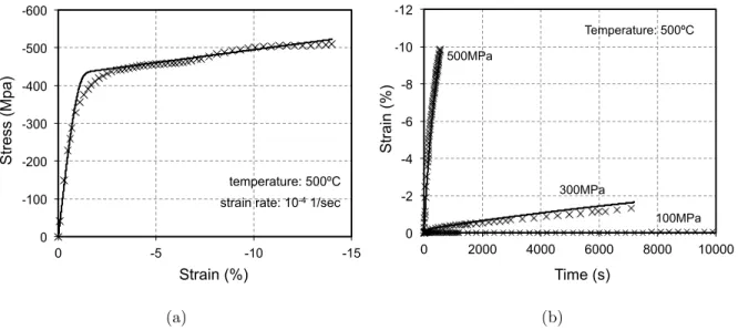
Strain (%) St re ss (Mp a) (a) -12 -10 -8 -6 -4 -2 0 0 2000 4000 6000 8000 10000 C re ep St ra in (% ) Time (sec) Temperature: 500ºC 500MPa 300MPa 100MPa Time (s) St ra in (% ) (b)
Figure 4: Comparisons between the simulations of the calibrated model and experimental results at 500 Ca) Uniaxial test b) Creep tests at 300 MPa and 500 MPa, respectively.
the parameters at each temperature are determined, a linear evolution of these parameters with respect to the temperature is considered.
To calibrate the model parameters related to the phase transformation, transformation-induced plasticity and the evolution of retained martensite, loading biased cycles at di↵erent stress levels are required. Three tests at di↵erent stress levels : 0 MPa, 400 MPa and 500 MPa (experiments #1, #15, #16) are utilized for this purpose. Viscoplastic strains that appear on tests #15 and #16 are subtracted using the additive viscoplastic model with the previously calibrated model parameters, and the thermoelastic strains are subtracted based on the thermoelastic parameters already identified. At each stress level, it is therefore possible to obtain the part of the strain that is related to the rate-independent inelastic phenomena. The resultant inelastic strain is composed of contributions from transformation, plasticity induced by transformation and retained martensite. Based on the evolution of these strains at the end of each cooling/heating cycle, the transformation strain magnitude, the transformation-induced plasticity and retained martensite parameters are determined for each stress level and each cycle. Note that for the following simulations, a piecewise linear relationship is utilized to obtain the evolution of the transformation-induced plasticity and retained martensite parameters with respect to the stress magnitude, while the transformation strain magnitude
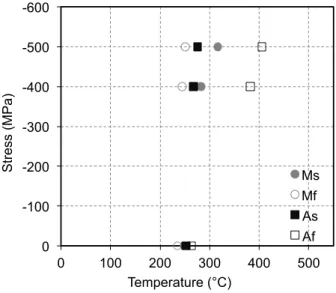
-600 -500 -400 -300 -200 -100 0 0 100 200 300 400 500 St re ss (MPa ) Temperature (°C) Ms Mf As Af
Figure 5: Experimental uniaxial compressive stress - temperature phase diagram for the T i50.5P d30N i19.5
HTSMA
evolution is described by an empirically motivated exponential relation (given in eq. 3.8). An experimental phase diagram is determined based on the transformation temperature obtained from the tangent intersection method applied to the strain-temperature response of the three isobaric tests (at respectively 0 MPa, 400 MPa and 500 MPa), performed at a cooling/heating rate of 20 C/min, between the thermoelastic regime and the transformation regime (see Fig. 5). From this phase diagram, and the strain magnitude of the transformation strain and TRIP strain, the nine model parameters that enter in the transformation driving
force are determined (⇢ s0, ⇢ u0, a1, a2, a3, Y0t, D, n1 and n2) using the procedure detailed
by Lagoudas et al. (2012).
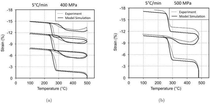
The comparison between model simulation and experimental results are presented in Fig. 6 for the two load-biased tests performed at 400 MPa and 500 MPa at a cooling/heating rate of 20 C/min (tests # 15-16, respectively). A good agreement is observed between the calibrated model and the overall evolution of strains that were observed experimentally. It is noted that a discrepancy is observed for the reverse transformation temperature, since the model considers a single slope in the uniaxial stress-temperature phase diagram for the transformation limits that corresponds to the onset and the end of reverse transformation. The value for this single slope has been taken to minimize the discrepancy between the
-14 -12 -10 -8 -6 -4 -2 0 0 100 200 300 400 500 600 St ra in (% ) Temperature (°C) Experimental Simulation !"#$%&'( ) )*"")+,-) ./012'&1(3) +4516),215'784() (a) -18 -16 -14 -12 -10 -8 -6 -4 -2 0 0 100 200 300 400 500 600 St ra in (% ) Temperature (°C) Experimental Simulation !"#$%&'( ) )*"")+,-) ./012'&1(3) +4516),215'784() (b)
Figure 6: Comparisons between the model simulations and experimental results for isobaric thermal cycling at a cooling/heating rate of 20 C/min at a) 400 MPa b) 500 MPa. Experimental data (grey lines) and current model simulations (black lines) are shown.
calibrated model and the experimental results. Thus, for the forward transformation the
average slope between Ms and Mf was selected, while for the reverse transformation only
the slope of Af was used.
4.2. Numerical Implementation
To perform numerical simulations of the considered HTSMA behavior, the developed model has been implemented in a Finite Element Analysis software (ABAQUS) as a user material subroutine. The implementation procedure follows the method proposed by Hartl et al. (2010b) for the implementation of a constitutive model that considers the simultaneous occurrence of phase transformation and viscoplasticity. The implementation of the consti-tutive model consists of the computation of the current stress, based on the total strain
and temperature increments. The evolution equations for "t, ⇠R, "tp, and "vp are integrated
over the increment duration. To solve those nonlinear equations, a form of the return map-ping algorithm, the convex cutting plane algorithm (Qidwai and Lagoudas, 2000), has been adopted. In the sequel, the index n denotes time step, while the index k refers to the iteration step during a specific time step.
The computation of the value of the transformation strain, TRIP strain, and viscoplastic strain in the current ”k +1”th iteration step depends on the increment of the volume fraction of martensite and the respective current direction tensors:
"t(k+1) n+1 = "tn+ ⇣ ⇠(k+1)n+1 ⇠n ⌘ ⇤t( (k)n+1), "tp(k+1) n+1 = "tpn+ ⇣ ⇠n+1(k+1) ⇠n ⌘ ⇤tp( (k)n+1), "vp(k+1) n+1 = "vpn+ t ˙p(k+1)n+1 ⇤vp( (k) n+1). (4.38)
The accumulated detwinned martensite volume fraction is updated as
⇣d(k+1)n+1 = ⇣dn+⇣⇠n+1(k+1) ⇠n ⌘
⇠d, (4.39)
while the irrecoverable part of the volume fraction of martensite is computed as
⇠R(k+1)n+1 = ⇠Rn+⇣⇠d(k+1)n+1 ⇠dn⌘⇤R, (4.40) where ⇤R = 8 > > < > > : w2C1R e ⇣ d/CR 2 , ⇠ > 0, (1 w2)C1R e ⇣ d/CR 2 , ⇠ < 0. (4.41)
The updated values for ⇠ and ˙p are obtained following the method proposed by Hartl et al. (2010b), i.e. satisfying the following two conditions
t(k+1) n+1 = t(k)n+1+ t(k)n+1 ' 0, vp(k+1)n+1 = vp(k)n+1+ vp(k)n+1 ' 0, (4.42) where vp(k+1) n+1 = * ¯(k+1)n+1 fvp Yvp Ka +Na ˙p(k)n+1. (4.43)
The re-initialization of the primary creep in the expression of the viscoplastic hardening occurs when the material is in a martensitic state. The accumulated viscoplastic strain p is additively decomposed into two contributions:
p = p1+ p2, (4.44)
where p1 and p2 are the accumulated plastic strains generated during the primary and the
secondary creep regime, respectively. The primary creep occurs until the exponential con-tribution of the viscoplastic hardening energy becomes negligible, i.e.
1 e Q3p ' 0. (4.45)
When the volume fraction of martensite reaches 1, the accumulated plastic strain p in
the expression of the viscoplastic hardening is set to p2 to represent the re-initialization of
the primary creep. We note though that the re-initialization a↵ects only the viscoplastic hardening function, while the total accumulated viscoplastic strain p retains its value and is not reduced.
4.3. Prediction of the behavior of a compression specimen
To determine the model prediction capabilities, two load-biased actuation tests were performed under a constant load that correspond to an average stress of 400 MPa and 500 MPa. These tests were performed in a range of temperatures from 100 C to 500 C. The heating/cooling rate was set to 5 C/min. This rate was slow enough to induce significant viscoplastic strains in the HTSMA.
The investigation of the behavior of a compression specimen used for the material char-acterization is performed using the constitutive model implemented in a Finite Element Analysis software (ABAQUS). According to geometric and loading symmetries, an axisym-metric model is defined, composed of 390 axisymaxisym-metric (generalized plane strain) quadratic elements. To describe accurately the time-dependent response of the HTSMA plot, a mini-mum of 60 time increments per minute is imposed during the heating/cooling steps. Note that a contact condition is imposed at the top and bottom surface of the plot, with an im-posed tangential friction. The friction parameter has been measured experimentally and is taken to be 0.2. A comparison between the model predictions and the experimental results is shown in Fig. 7. The model predicts with a good accuracy the overall thermomechanical behavior of the specimen.
-18 -15 -12 -9 -6 -3 0 0 100 200 300 400 500 St ra in (% ) Temperature (°C) Experimental Simulation !"#$%&' ( ()**(+,-( ./012&%1'3( +4516(7&%86-94'( (a) -18 -15 -12 -9 -6 -3 0 0 100 200 300 400 500 St ra in (% ) Temperature (°C) Experimental Simulation !"#$%&' ( (!))(*+,( -./01&%0'2( *3405(6&%75,83'( (b)
Figure 7: Comparison between model predictions and experimental compressive stress-strain response under isobaric thermal cycling at a cooling/heating rate of 5 C/min at a) 400 MPa b) 500 MPa.
To further investigate the behavior of such a HTSMA actuator (under 400 MPa average stress), the contour plots of the equivalent von Mises stress, the retained martensite volume
fraction, the component of the TRIP strain "tp22, and the component "vp22 of the viscoplastic
strain are shown in Fig. 8 at the end of each of the three cooling/heating cycles. The direction “2” is colinear with the axis of revolution of the compression specimen. These components are characteristic of the non-recoverable strain that is exhibited by the specimen. It is observed that the distribution of the volume fraction of retained martensite is almost constant everywhere in the specimen. However, the TRIP strain and the viscoplastic strain fields are heterogeneous. The TRIP strain magnitude varies from 0.04 to 0.1 at the end of the third cycle, while the viscoplastic strain varies from 0 to 0.06. The reason for such an heterogeneity is that the friction condition imposed at the top and bottom surface induces an heterogeneity of the stress field (see Fig. 8) throughout the specimen, which modifies the local evolution of the TRIP and viscoplastic strains. Indeed, these two components are strongly dependent on the stress magnitude. The results indicate that the stress-strain behavior obtained experimentally, considering an homogeneous stress state in the material, corresponds to an average value of these quantities over the specimen. FEA analysis of such
a specimen allows for a better description of the stress state and the evolution of strain inside the specimen.
4.4. Numerical simulations of a HTSMA wave spring
To demonstrate the capabilities of the proposed model and to analyze the behavior of three-dimensional structures, we simulate an actuator with a more complex geometry. We consider a HTSMA wave spring, made out of several wave rings stacked on top of each other to create an actuator capable of providing large actuation displacement under significant forces. Specifically, 10 wave collars are considered, with an inner radius of 16.4 mm, an outer radius of 20 mm and a thickness of 0.195 mm. The total height of the wave spring is 9 mm. The initial geometry of the wave spring is shown in Figure 9.
The FEM model considers a unique set of two antagonist wave collars. Note that this corresponds to 1/5 of the total height of the complete wave spring.The considered thermo-mechanical loading path is as follows:
1. At T = 500 C, an axial compressive load of 10 N is applied in 10s
2. Maintaining the biasing load, the wave spring is cooled uniformly to T = 100 C in 80 min, with a constant cooling rate of 5 C/min
3. Maintaining the biasing load, the wave spring is heated uniformly to T = 500 C in 80 min, with a constant heating rate of 5 C/min
4. Repeat step 2 and 3 (2 times).
A second load path is considered, similar to the first one, except that the cooling/heating rate is set to 20 C/min. The biasing load is applied to the wave spring using a rigid plane. A contact condition is imposed between a rigid top plane and the top ring, and between a rigid bottom plane and the bottom ring. Moreover, a contact condition is also imposed between the surfaces of each layer. A tangential friction is considered, with a value of 0.2 for the friction coefficient.
The evolution of the normalized length reduction of the spring (according to its height) with respect to the temperature is shown in Fig. 10. The length reduction due to the applied load is 0.42 of the total height of the spring. It is seen during the first cooling cycle that a cooling rate of 20 C/min and 5 C/min are slow enough to induce viscoplastic strain from
Figure 8: Numerical results of a HTSMA compression plot under under isobaric loading (400 MPa). Repre-sentation of the material state at the end of each of the three cooling/heating cycle at 5 C/min.
!"
#"
$"
Figure 9: Initial geometry of the wave spring
0
0.1
0.2
0.3
0.4
0.5
0.6
0.7
0.8
0.9
1
0
100
200
300
400
500
N
orma
lize
d
le
ng
th
re
du
ct
io
n
Temperature (°C)
5°C/min 20°C/min !" !" !"Figure 10: Evolution of the normalized length reduction of the wave spring for two di↵erent cooling/heating rates (5 C/min and 20 C/min)
500 C to 400 C. However the slow cooling rate (5 C/min) induce a length reduction of the spring that is significantly higher than the fast cooling rate (20 C/min). Indeed, a fast cooling rate results in less creep and thus less overall irrecoverable shape change. Cooling further below 190 C, the appearance of transformation strain accompanied with TRIP strain induces a large reduction of the spring height. In the two cases, the shape of the spring is very close to a pile of rings that have become totally flat. Below 190 C, there is no further reduction of the spring height and the spring is in a fully martensitic state. Upon heating, a fraction of the initial length of the spring is recovered as the HTSMA undergoes reverse martensitic transformation. At temperatures higher than 400 C, additional viscoplastic strain is generated. The irrecoverable nature of the viscoplastic strain, the TRIP strain and the e↵ect of retained martensite induce a change in the geometry of the spring at the reference high temperature (500 C), with a reduced length according to the initial geometry. During the following cycles, the geometry at the reference high temperature continues to change from cycle to cycle, which means that irrecoverable strains are generated. Actually, the same sequence of the deformation mechanisms appears during the following cycles, however according to what has been observed for the uniaxial behavior, the amount of irrecoverable strain due to TRIP, retained martensite and viscoplasticity is reduced.
Detailed analysis results for the cases of 5 C/min and 20 C/min cooling/ heating rates are provided in Fig. 11. The contour plot of the von Mises stress is provided at the end of the loading stage (denoted by point ’L’ in Fig. 10) and at the end of the third cycle (denoted by point ’3’ in Fig. 10). Both of these points correspond to a spring with a uniform temperature that corresponds to the reference temperature (500 C). The von Mises stress is similar for the two simulations, since the same loading is applied, fast enough to avoid any creep at 500 C. At the end of the third cycle, the stress repartition has been modified, with an overall decrease of the stress amplitude throughout the spring. This comes from the change in the spring shape, specifically the wave collars have become more flat, due to the appearance of irrecoverable strains over the three cycles. Thus, due to the di↵erences in the generated irrecoverable strain in the two cases, the same applied load leads to a di↵erent stress repartition. The von Mises stress is slightly di↵erent between the two simulations with the maximum stress being lower for the slow cooling/heating rate (5 C/min). It is also
Figure 11: Contour plot, for two antagonist collars, of Mises stress at the end of the application of the load, and contour plot of the Mises stress, the accumulated viscoplastic strain and the volume fraction of retained martensite for two cooling/heating rates (5 C/min and 20 C/min)
observed that the accumulated irrecoverable viscoplastic strain is higher in the case of the slow cooling rate. Interestingly, the amount of retained martensite is reduced in this case. In fact, the amount of irrecoverable viscoplastic strain has induced a more pronounced flat shape during the martensitic transformation (see Fig. 10) at the reference temperature, resulting in an overall lower stress amplitude throughout the wave collars. This reduced stress amplitude induces, during forward transformation, a smaller amount of detwinned martensite. However, the amount of retained martensite depends on the accumulated detwinned martensite volume fraction. Thus, in this case, the amount of retained martensite is reduced.
Conclusions
The focus of this work is the study of the simultaneous transformation and viscoplas-tic behavior of high temperature shape memory alloys during multiple thermomechanical cycles. To account for the di↵erent deformation mechanisms that occur in the HTSMAs, a new constitutive model is developed. The model accounts for the following mechanisms: viscoplasticity, transformation, plasticity during transformation, and retained martensite. Such mechanisms significantly influence the actuation response and need to be accounted for in the design of HTSMA actuators. A set of experiments related to a calibration pro-cedure have been proposed for a complete characterization of the material behavior. The proposed model, after proper calibration, is able to accurately predict the evolution of the actuation behavior during cyclic loading. Finally, a numerical implementation of the pro-posed thermomechanical constitutive model allows the solution of complex, time-dependent boundary value problems, for the numerical simulation of the response of HTSMA actua-tors. Such numerical implementation is highly challenging since many variables are evolving simultaneously. The choice of an efficient algorithm (i.e., the cutting plane algorithm) al-lows the simulation of HTSMA structures subjected to complex cyclic loadings for industrial applications.
5. Acknowledgment
The authors acknowledge the financial support provided by NASA Glenn Research Cen-ter, project NNX07AB56A, for this work. We would like to thank Dr. Ronald Noebe for
helpful discussions. The support of the NSF International Institute of Materials for Energy Conversion (IIMEC), award #0844082, is acknowledged. The authors would also like to thank Mr. Uri Desai, for performing some of the experiments presented in this paper.
References
Andersen, A., P. D. S. A., Sangesland, S., July 1999. Detailed study of shape memory alloys in oil well applications. Tech. rep., SINTEF Petroleum Research, Trondheim, Norway. Bo, Z., Lagoudas, D. C., 1999a. Thermomechanical modeling of polycrystalline SMAs under
cyclic loading, Part I: Theoretical Derivations. International Journal of Engineering Science 37, 1089–1140.
Bo, Z., Lagoudas, D. C., 1999b. Thermomechanical modeling of polycrystalline SMAs under cyclic loading, Part III: Evolution of plastic strains and two-way shape memory e↵ect. International Journal of Engineering Science 37, 1175–1203.
Boyd, J., Lagoudas, D. C., 1996. A thermodynamical constitutive model for shape memory materials. Part I: the monolithic shape memory alloy. International Journal of Plasticity 12 (6), 805–842.
Brinson, L. C., 1993. One-dimensional constitutive behavior of shape memory alloys: Ther-momechanical derivation with non-constant material functions and redefined martensite internal variable. Journal of Intelligent Material Systems and Structures 4, 229–242. Cai, W., Tanaka, S., Otsuka, K., 2000. Thermal cyclic characteristics under load in a
T i50.6P d30N i19.4 alloy. Materials Science Forum 327-328, 279–282.
Chemisky, Y., Duval, A., Patoor, E., Zineb, T. B., 2011. Constitutive model for shape memory alloys including phase transformation, martensitic reorientation and twins ac-commodation. Mechanics of Materials 43 (7), 361–376.
Coleman, B., Noll, W., 1963. The thermodynamics of elastic materials with heat conduction and viscosity. Archive for Rational Mechanics and Analysis 13, 167–178.
DeCastro, J. A., Melcher, K. J., Noebe, R. D., 2005. System-level design of a shape memory alloy actuator for active clearance control in the high-pressure turbine. AIAA (3988–4002). Golberg, D., Xu, Y., Murakami, Y., Morito, S., Otsuka, K., T., U., Horikawa, H., 1994.
Im-provement of a T i50P d30N i20 high-temperature shape memory alloy by thermomechanical
treatment. Scripta Metallurgica et Materialia 30 (10), 1349–1354.
Golberg, D., Xu, Y., Murakami, Y., Morito, S., Otsuka, K., T., U., Horikawa, H., 1995a.
Characteristics of T i50P d30N i20 high-temperature shape memory alloy. Intermetallics 3,
35–46.
Golberg, D., Xu, Y., Murakami, Y., Otsuka, K., T., U., Horikawa, H., 1995b.
High-temperature shape memory e↵ect in T i50P d50 xN ix(x = 10, 15, 20) alloys. Materials
let-ters 22, 241–248.
Hartl, D., Lagoudas, D., 2009. Constitutive modeling and structural analysis considering simultaneous phase transformation and plastic yield in shape memory alloys. Smart Ma-terials and Structures 18 (1–17).
Hartl, D., Mooney, J., Lagoudas, D., Calkins, F., Mabe, J., 2010a. Use of a Ni60Ti shape
memory alloy for active jet engine chevron application: II. experimentally validated nu-merical analysis. Smart Materials and Structures 19, 015021.
Hartl, D. J., Chatzigeorgiou, G., Lagoudas, D. C., 2010b. Three-dimensional modeling and numerical analysis of rate-dependent irrecoverable deformation in shape memory alloys. International Journal of Plasticity 26 (10), 1485 – 1507.
Khalil, W., Mikolajczak, A., Bouby, C., Ben Zineb, T., 2012. A constitutive model for fe-based shape memory alloy considering martensitic transformation and plastic sliding coupling: Application to a finite element structural analysis. Journal of Intelligent Material Systems and Structures 23, 1143–1160.
Kockar, B., Karaman, I., Kim, J., Chumlyakov, Y., 2006. A method to enhance cyclic reversibility of nitihf high temperature shape memory alloys. Scripta Materialia 54 (12), 2203–2208.
Kumar, P. K., Desai, U., Monroe, J., Lagoudas, D. C., Karaman, I., Noebe, R., Bigelow, G., 2011. Experimental investigation of simultaneous creep, plasticity and transformation of
Ti50.5Pd30Ni19.5 high temperature shape memory alloy during cyclic actuation. Materials
Science and Engineering A (In Press) 530, 117 – 127.
Kumar, P. K., Lagoudas, D. C., 2010. Experimental and microstructural characterization of simultaneous creep, plasticity and phase transformation in ti50pd40ni10 high-temperature shape memory alloy. Acta Materialia 58 (5), 1618 – 1628.
Lagoudas, D., Hartl, D., Chemisky, Y., Machado, L., Popov, P., 2012. Constitutive model for the numerical analysis of phase transformation in polycrystalline shape memory alloys. International Journal of Plasticity 32-33, 155–183.
Lagoudas, D. C. (Ed.), 2008. Shape Memory Alloys: Modeling and Engineering Applications. Springer.
Lagoudas, D. C., Bo, Z., 1999. Thermomechanical modeling of polycrystalline SMAs under cyclic loading, Part II: Material characterization and experimental results for a stable transformation cycle. International Journal of Engineering Science 37, 1141–1173.
Lagoudas, D. C., Chatzigeorgiou, G., Kumar, P., 2009. Modeling and experimental study of simultaneous creep and transformation in polycrystalline high-temperature shape memory alloys. Journal of Intelligent Material Systems and Structures 20, 2257–2267.
Lagoudas, D. C., Entchev, P., 2004a. Modeling of transformation-induced plasticity and its e↵ect on the behavior of porous shape memory alloys: Part I: Constitutive model for fully dense SMAs. Mechanics of Materials 36 (9), 865–892.
Lagoudas, D. C., Entchev, P. B., 2004b. Modeling of transformation-induced plasticity and its e↵ect on the behavior of porous shape memory alloys. part i: constitutive model for fully dense smas. Mechanics of Materials 36 (9), 865 – 892.
Leclercq, S., Lexcellent, C., 1996. A general macroscopic description of the thermomechanical behavior of shape memory alloys. Journal of the Mechanics and Physics of Solids 44 (6), 953–980.
Lemaitre, J., Chaboche, J.-L., 2002. Mechanics of solid materials. Cambridge University Press.
Liang, C., Rogers, C. A., 1990. One-dimensional thermomechanical constitutive relations for shape memory materials. Journal of Intelligent Material Systems and Structures 1, 207–234.
Lidquist, P., Wayman, C. M., 1990. Shape memory and transformation behavior of
marten-sitic T i P d N i and T i P t N i alloys, Engineering Aspects of Shape Memory Alloys.
Butterworth-Heinemann, London.
Lindquist, P., 1988. Structure and transformation behavior of martensite ti-(ni, pd) and ti-(ni, pt) alloys. Ph.D. thesis, Univesity of Illinois at Urbana-Champaign.
Ma, J., Karaman, I., Noebe, R. D., 2010. High temperature shape memory alloys. Interna-tional Materials Review 55 (59), 257–315.
Noebe, R., Padula II, S., Bigelow, G., Rios, O., A., G., Lerch, B., 2006. Properties of a
N i19.5P d30T i50.5 high-temperature shape memory alloy in tension and compression. In:
Proceedings of SPIE. Vol. 6170. pp. 279–291.
Otsuka, K., Wayman, C. M. (Eds.), 1999. Shape Memory Materials. Cambridge University Press, Cambridge.
Padula II, S., Bigelow, G., Noebe, R., Gaydosh, D., Garg, A., 2006. Challenges and progress in the development of high-temperature shape memory alloys based on NiTiX compositions for high-force actuator applications. In: Proceedings of the International Conference on Shape Memory and Superelastic Technologies. ASM International, Metals Park, OH. Panico, M., Brinson, L., 2007. A three-dimensional phenomenological model for martensite
reorientation in shape memory alloys. Journal of the Mechanics and Physics of Solids 55, 2491–2511.
Press, W., Teukolsky, S., Vetterling, W., Flannery, B., 1992. Numerical Recipes in C - The Art of Scientific Computing - Second Edition. Cambridge University Press, Cambridge.
Pu, Z., Tseng, H., Wu, K., 1995. Martensite transformation and shape-memory e↵ect of NiTi-Zr high- temperature shape-memory alloys. In: SPIE proceedings. Vol. 2441. p. 171. Qidwai, M. A., Lagoudas, D. C., 2000. Numerical implementation of a shape memory al-loy thermomechanical constitutive model using return mapping algorithm. International Journal for Numerical Methods in Engineering 47, 1123–1168.
Savi, M., Paiva, A., Baˆeta-Neves, A. P., Pacheco, P. M. C. L., 2002. Phenomenological mod-eling and numerical simulation of shape memory alloys: A thermo-plastic-phase transfor-mation coupled model. Journal of Intelligent Material Systems and Structures 13, 261–273. Schwertel, J., Schinke, B., 1996. Automated evaluation of material parameters of viscoplastic constitutive equations. Journal of Engineering Materials and Technology 118 (3), 273–280. Sedlak, P., Frost, M., Benesova, B., Zineb, T. B., Sittner, P., 2012. Thermomechanical model for niti-based shape memory alloys including r-phase and material anisotropy under multi-axial loadings. International Journal of Plasticity 39 (0), 132 – 151.
Tanaka, K., Kobayashi, S., Sato, Y., 1986. Thermomechanics of transformation pseudoelas-ticity and shape memory e↵ect in alloys. International Journal of Plaspseudoelas-ticity 2, 59–72. Thoma, P. E., Boehm, J. J., 1999. E↵ect of composition on the amount of second phase and
transformation temperatures of N ixT i90 xHf10 shape memory alloys. Materials Science
and Engineering A 273-275, 385–389.
Wu, S., Wayman, C., 1987. Martensitic transformations and the shape-memory e↵ect in
T i50N i10Au40 and T i50Au50 alloys. Metallography 20 (3), 359–376.
Zaki, W., Zamfir, S., Moumni, Z., 2010. An extension of the zm model for shape memory alloys accounting for plastic deformation. Mechanics of Materials 42 (3), 266 – 274.