Science Arts & Métiers (SAM)
is an open access repository that collects the work of Arts et Métiers Institute of
Technology researchers and makes it freely available over the web where possible.
This is an author-deposited version published in: https://sam.ensam.eu Handle ID: .http://hdl.handle.net/10985/9566
To cite this version :
Mamoun FELLAH, Mohamed LABAIZ, Omar OSSALA, Leila DEKHIL, Ahlem TALEB, Hadda REZAG, Alain IOST - Tribological behavior of Ti-6Al-4V and Ti-6Al-7Nb Alloys for Total Hip Prosthesis - Advances in Tribology p.1-13 - 2014
Any correspondence concerning this service should be sent to the repository Administrator : archiveouverte@ensam.eu
Research Article
Tribological behavior of Ti-6Al-4V and Ti-6Al-7Nb
Alloys for Total Hip Prosthesis
Mamoun Fellah,
1Mohamed Laba
\z,
1Omar Assala,
1Leila Dekhil,
1Ahlem Taleb,
1Hadda Rezag,
1and Alain Iost
21Surface Engineering and Tribology Group, Laboratory of Metallurgy and Engineering Materials, BADJI Mokhtar-University,
P.O. Box 12, 23000 Annaba, Algeria
2Laboratory of MSMP, Arts et Metiers ParisTech, 8 Louis XIV Street, 59046 Lille Cedex, France
The aim of the study is to evaluate the friction and wear behavior of high-strength alloys Ti-6Al-7Nb used in femoral stem and compare it with a Ti-6Al-4V alloy cylindrical bar corresponding to ISO 5832-3 part 3/01-07-199 standard. The tribological behavior was investigated by wear tests, using ball-on-disc and pin-on-disc tribometers. These tests consisted of measuring the weight loss and the friction coefficient of samples. The oscillating friction and wear tests have been carried out in ambient with oscillating tribotester in accordance with standards ISO 7148, ASTM G99-95a, and ASTM G133-95 under different conditions of normal loads (3, 6, and 10 N) and sliding speeds (1, 15, and 25 mm⋅s−1). As counter pairs, a 100Cr6 steel ball with 10 mm in diameter was used.
Results show that the two alloys had similar friction and wear performance, although their grain structures and compositions are different. Occurrence of large frictional occurred, is probably caused by formation and periodic, localized fracture of a transfer layer. Higher friction with larger fluctuation and higher wear rate was observed at the higher siding speed. The Ti-6Al-4V wear mechanism transforms from ploughing and peeling off wear at low sliding speed to plastic deformation and adhesive wear.
1. Introduction
Titanium and its alloys have been used as implant materials due to their very good mechanical and corrosion resistance and biocompatibility [1–4]. The most used biomaterial was commercially pure titanium (CP-Ti) [5, 6], although it has been pointed out that CP-Ti has disadvantages of low strength, difficulty in polishing, and poor wear resistance. Therefore, titanium is still insufficient for high-stress appli-cations, for example, long spanned fixed prostheses and the frameworks of removable partial dentures [7,8].
Ti-6Al-4V alloy, originally developed as an aeronautical material, has been tested as a replacement for CP-Ti, because of its high mechanical properties with sufficient corrosion resistance [9–11]. However, the cytoxicity of elemental vana-dium is questionable [12,13]. Subsequently, some researches prove that vanadium and aluminum ions released from this ternary alloy can induce cytotoxic effects or neurological
disorders, respectively [14]. Also, for long term, this alloy has transferred insufficient load to adjacent bones, resulting in bone resorption and eventual loosening of the implant [15,16].
Another ternary vanadium free 𝛼 + 𝛽 alloy, used as implant material, was Ti-6Al-7Nb alloy [17–19] that revealed improved mechanical characteristics, corrosion resistance, and biocompatibility. Alloy was developed for orthopedics application as a wrought material and has been evaluated as a new alloy for total hip prostheses. Niobium exhibits a similar effect to vanadium in stabilizing𝛽 phase in the Ti-Nb binary system, which is necessary for providing the𝛼 + 𝛽 two-phase structure. Therefore, niobium was used as the ternary element to produce the desirable microstructure in the Ti-6Al-7Nb alloy [20].
As compared with 6Al-4V alloy, in a tensile test, Ti-6Al-7Nb alloy shows slightly lower strength and about 40% higher elongation. In addition, after long term immersion in
1.0% lactic acid, the amount of titanium ion released from Ti-6Al-7Nb alloy was less than that from Ti-6Al-4V alloy and comparable to that from CP-Ti [21]. Ti-6Al-7Nb alloy showed slightly lower castability than that of CP-Ti but less casting porosity, which is advantageous in terms of reliability of castings [21].
Although Ti-6Al-7Nb alloy castings have been inves-tigated for orthopedics application from several aspects, such as mechanical properties, corrosion resistance, and castability, no studies have reported on its friction and wear resistance, which is an important factor for total hip prosthe-ses material. In this study, friction and wear characteristics of Ti-6Al-7Nb and Ti-6Al-4V alloys were evaluated by ball-on-disc and pin-ball-on-disc tribometers in accordance with ISO 7148, ASTM G99-95a, and ASTM G133-95 standards.
2. Materials and Methods
2.1. Materials Characterization. The materials used in this
study are the Ti-6Al-7Nb as a total hip prosthesis (femoral stem) and Ti-6Al-4V that was cut from a titanium cylindrical bar corresponding to ISO 5832-3 part 3/01-07-199 (supplied by ENSAM, Lille, France). The chemical composition of titanium alloys used in this study is specified inTable 1.
The alloy surfaces were ground with 600 SiC abrasive grinding paper and polished with colloidal silica since it is known that the fixation of the implant is greatly dependent on good mechanical interlocking between the rough surface of the implant and tissue [22]. All the samples were cleaned in an ultrasonic bath with acetone, ethanol, and distilled water, for 10 min in succession and then dried in hot air and saved in the desiccators till their use.
2.1.1. Surface and Microstructural Analysis. An acidic etchant
(3 ml HF, 6 ml HNO3 and 100 ml H2O for 10 s) was used to reduce the influence of surface hardening, the microstructure was studied using optical microscopy (Leica DMLM). The alloys chemical composition presented in
Table 1 was acquired using spectrometer (Spectrolab) and energy-dispersive spectroscopy (EDS using PHILIPS XL 30 ESEM-FEG and EDX IMIX-PTS). The phases presented in alloy microstructure were identified by X-Ray diffractometry (Intel CPS 120/Brucker AXS) using Cu K𝛼 generated at 40 kV and 35 mA. Scanning electron microscopy (SEM) and energy-dispersive X-ray (EDX) analyses were used to study the chemical composition of investigated materials. The roughness of the samples in 3D was studied using Surface Data Veeco: Mag 5.0 X, Mode VSI.
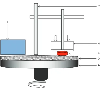
2.2. Tribological Study. Pin-on-disc, ball-on-disc, and
tribo-logical tests (Figures 1 and 2) were carried out using the following prosthetic materials: Ti-6Al-4V and Ti-6Al-7Nb alloys, against 100Cr6 steel and abrasive paper number 320 (Sic).
2.2.1. Weight Loss (Pin-on-Disc). The contact pair, which
studies the tribological pair, is, in this case, the sample (Ti-6Al-4V, Ti-6Al-7Nb and sandpaper (320 abrasive papers)).
2 4 5 6 3 1
Figure 1: Scheme of plane contact (pin-on-disc): (1) speed regulator, (2) support, (3) rotating tray, (4) load applied, (5) sample, (6) retaining frame; friction pairs used: Ti-6Al-4V and Ti-6Al-7Nb sliding against number 320 abrasive paper; sliding distance: 1400 m. Table 1: Chemical composition, hardness, and microstructure of the metallic materials studied.
Ti C Mo Ta Fe Al Nb V Ti-6Al-7Nb Bal 0.004 0.005 0.46 0.10 6.2 7.4 — Hardness: 340± 10 HV Microstructure: 80%𝛼—20% 𝛽 Ti-6Al-4V Bal 0.03 0.01 — 0.10 6.7 — 4.2 Hardness: 360± 10 HV Microstructure: 80%𝛼—20% 𝛽
The parameters taken into account for this test are the applied load and the rotational speed. The test time and sliding distance (1400 m) are kept constant, while the weight loss is determined as a the difference in the weight of the sample weighed before and after the test. Microelectronic balance, whose accuracy is of the order 10−3g, was used for weight measurements. The samples were cleaned with acetone before each weight and the surface roughness of the test sample is measured before and after the test.
2.2.2. Friction and Wear Behavior (Ball-on-Disc). Friction
and wear tests have been carried out, in ambient air with oscillating tribometer in accordance with ISO 7148, ASTM G99-95a, and ASTM G133-95 standards (Figure 2).
Samples were prepared for testing in accordance with ASTM F136-02, ASTM F86-01, and ASTM E1078-02. Each specimen was thoroughly cleaned by ethyl alcohol, then cleaned in ultrasonic bath for 60 minutes, and dried in hot air afterwards. After that, samples were cleaned in isopropyl alcohol by staying in the solution for 60 minutes and dried in hot air. Samples were stored in a desiccator, prior to testing. Duration of each test was 40000 cycles (distance of 40 m), whereat one cycle is represented by full amplitude
(a) 1 2 3 4 5 (b)
Figure 2: (a) Photography of ball-on-disc contact and tribotester system. (1) Table in alternative movement. (2) A sensor to measure heat and humidity. (3) Ball 100Cr6 steel. (4) Load applied𝐹. (5) Sample.
Table 2: Work condition of alternative movement wear test (oscil-lating tribotester).
Friction pairs used (1) 100Cr6 steel/Ti-6Al-7Nb (2) 100Cr6 steel/Ti-6Al-4V
Sliding speed 1, 15 and 25 mm s−1
Applied load (N) 3, 6 and 10 N
Wear track radius 5 mm
100Cr6 steel diameter 10 mm
Temperature 25∘C
Humidity 38%
sliding distance (half amplitude, 0.25 mm). Selected sliding velocities lie in the range typically found in hip joints (1, 15, and 25 mm⋅s−1) under different normal loads (3, 6, and 10 N).
The friction coefficient, that is, dynamic friction coefficient, was automatically recorded during the testing, using data acquisition software. Simultaneously, the friction coefficient curve was recorded and plotted. Test conditions are shown in
Table 2.
3. Results
3.1. Surface and Microstructural Analysis. Samples of the
titanium-based alloys (Figure 3) were examined using (EDX) analysis. The spectra for the overall analysis are shown in Figures 4 and 5. In the case of Ti-6Al-4V alloy titanium, Ti peak is more pronounced than aluminum as expected in the EDX phases. Vanadium, molybdenum (Mo), and nickel are also present; for the Ti-6Al-7Nb, the Ti peak is more pronounced than that of aluminum(Al), niobium(Nb), iron (Fe), molybdenum (Mo), and tantalum (Ta) are also present. The chemical compositions of the studied samples were in compliance with that of a Ti-6Al-7Nb and Ti-6Al-4V, respectively.
3.1.1. Microstructure. The samples are mechanically
pol-ished and chemically etched with a solution of 3 mL HF, 6 mL HNO3, and 100 mL H2O for 10 s to reduce the influ-ence of surface hardening. The microstructure of titanium alloy is shown in Figures3(a) and3(b), respectively. Alloys microstructure consists of globular and acicular 𝛼 grains (white grains) within a matrix containing equiaxial grains𝛽 (dark grains). The acicular shape of the 𝛼 phase is present inFigure 3in an arrangement known as basket-weave which characterizes the Widmanst¨atten structure. The microstruc-ture of the Ti-6Al-4V alloy consists of alpha grains (white in the optical micrograph; (Figure 3(b)) and lamellar alpha plus beta grains (black inFigure 3(b)).
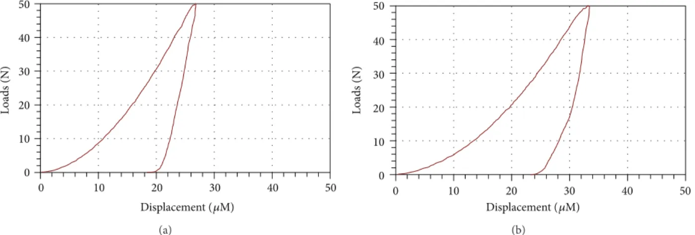
3.1.2. Microhardness. Microhardness experiments were
per-formed using a Zwick Roell Z 2.5 micro-compression tester type ZHU/Z 2.5, equipped with a diamond indenter, located in a room temperature of 22∘C and atmosphere of laboratory. Using the P-h (load-displacement) curves during micro-hardness experiments with a loading speed (0.2 mm⋅min−1),
under a maximum load of 50 N, each test was conducted three times, and the average values were calculated automatically by MCT as the load and displacement. The experimental P-h curve of Ti-6Al-7Nb and Ti-6Al-4V is shown inFigure 6.
3.1.3. Roughness Analysis. The studied substrates are of
bio-medical interest. They must therefore meet the standards imposed by the field of biomedicine particularly at the surface of the material deposited on the articular surfaces of hip prostheses in which Ti-6Al-4V and Ti-6Al-7Nb are the hip implant. The obtained roughness of the samples (Table 3and Figure 7) meets the standards of biomedicine, as specified in ISO 7206-2:1996 standard [23]. The roughness values were 5.03 and 0.01𝜇m for Ti-6Al-7Nb alloy before and after polishing, respectively, and 0.06𝜇m for Ti-6Al-4V after polishing.
43 𝜇m
35 𝜇m
𝛽
𝛼
(a) (b)
Figure 3: Optical micrographs of (a) Ti-6Al-7Nb and (b) Ti-6Al-4V alloys.
depot LSecs:195 Ti Al Nb KC n t 9.00 8.00 7.00 6.00 5.00 4.00 3.00 2.00 1.00 0.00 52 41 31 21 10 0
Figure 4: EDX spectrum of Ti-6Al-7Nb alloy.
Table 3: Roughness parameters of Ti alloy after polishing.
Parameters/(nm) Ti-6Al-7Nb Ti-6Al-4V
Ra 0.04 0.06
Rq 0.05 0.08
Rz 0.97 1.05
Rt 1.04 1.19
Ra: arithmetic average of absolute values, Rq: root mean squared, Rt: maximum height of the profile, and Rz: the average distance between the highest peak and lowest valley in each sampling length, ASME Y14.36M-1996 surface texture symbols.
3.2. Tribological Study
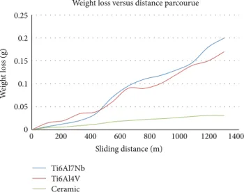
3.2.1. Weight Loss (Contact Plane). The weight loss (Figure 8) of titanium samples, tested at 3.5 N load, is approximately proportional to the number of disk revolutions. Neverthe-less, the wear was systematically greater to Ti-6Al-7Nb as expected. The behavior observed for both samples suggests that the wear mechanism during the test is the same (abrasive wear). In the case of Ti-6Al-4V samples, its weight loss was∼85% of the one observed for the Ti-6Al-7Nb samples. According to the Archard’s law, the volumetric loss of the material is inversely proportional to the hardness value of the material [24,25]. This implies that the higher the hardness of
the material, the smaller the volume loss. The present alloys exhibit significant difference in hardness values, so that the experimental sliding wear data correlate well with Archard’s law.
3.2.2. Friction Coefficient. Dependence of Ti-6Al-7Nb and
Ti-6Al-4V alloys coefficient of friction (COF) on sliding distance, that is, number of cycles, is given in Tables4and5
and from Figures9,10,11,12,13,14,15, and16, are almost the some in the load and speed conditions. The analysis of these curves permits it to distinguish several periods or successive regimes of friction and wear.
(1) The first is accommodation period, during which the friction coefficient increases rapidly is the surface of the first body the most ductile [26], in this case the steel. The roughness of the steel surface is reduced by plastic deformation.
(2) The second period is characterized by a slight decrease in the friction coefficient. Probably, the third body on the track generated by frictional wear of the steel plays a role comparable to that of a solid lubricant.
(3) The third period is defined by a significant increase in the friction coefficient. The third body is fragmented and oxidizes and probably plays an abrasive role. (4) The fourth and final period correspond to the
stabi-lization of the friction coefficient up 1400.
It is seen fromFigure 9, that the friction coefficient displays a lower value (approx. 0.248) up to 20 cycles and then it increased to the average 0.4 value between 40 and 1000 cycles. The reason might be due to oxide layer formed on titanium alloys and, therefore, the coefficient of friction showed the lower value. However, that oxide layer was torn and then 100Cr6 steel ball was completely touched on the substrate and, therefore, the friction coefficient obtained a higher value (0.538).
Figures 9and 10 display the evolution of friction coef-ficient curves of Ti-6Al-7Nb and Ti-6Al-4V, respectively, under different condition of applied loads and tow sliding speeds (15 and 25 mm⋅s−1). The results obtained showed the
7943 15 110 100 90 80 70 60 50 40 30 20 (002)𝛽Ti (110)𝛽Ti (101)𝛼Ti
(102)𝛼Ti (100)𝛼Ti (200)𝛽Ti (110)𝛼Ti TiAlNb 120 /logiciel diff rac p lus 2𝜃-scale In te l di te ct o r CPS 00-044-1294 (∗)-titanium-Ti
00-046-1212 (∗)-corundum, syn-𝛼-Al2O3
File: LABTIALN.RAW-WL1:1.936 ; creation: January 7, 2008, 13:53:40
UTC Phisico-chemical analysis center
Figure 5: XRD spectrum of Ti-6Al-7Nb alloy.
0 10 20 30 40 50 0 10 20 30 40 50 L o ads (N) Displacement (𝜇M) (a) 0 10 20 30 40 50 0 10 20 30 40 50 L o ads (N) Displacement (𝜇M) (b)
Figure 6: P-h curves during microhardness experiments with loading speed (0.2 mm⋅min−1), under a maximum load (50 N) of (a) Ti-6Al-4V,
(b) Ti-6Al-7Nb. (𝜇 m) 0.413 0.350 0.300 0.250 0.200 0.150 0.100 0.050 0.000 −0.050 −0.131 (a) 0.48 0.40 0.30 0.20 0.10 0.00 −0.10 −0.20 −0.30 −0.40 −0.50 −0.60 −0.71 (𝜇 m) (b)
0 0.05 0.1 0.15 0.2 0.25 0 200 400 600 800 1000 1200 1400 W eig h t loss (g) Sliding distance (m)
Weight loss versus distance parcourue
Ti6Al7Nb Ti6Al4V Ceramic
Figure 8: Weight loss of Ti alloys during wear sliding against abrasive paper. 0 0.1 0.2 0.3 0.4 0.5 0.6 0 500 1000 1500 2000 2500 CO F Distance (cycles) 15 mm·s−1,3 N 15 mm·s−1,6 N 15 mm·s−1,10 N 25 mm·s−1,3 N 25 mm·s−1,6 N 25 mm·s−1,10 N
Figure 9: Friction coefficient of Ti-6Al-7Nb alloy versus sliding distance at tow sliding speed (15 and 25 mm⋅s−1).
same form for all curves. The average COF value obtained at 15 mm⋅s−1and under 3 N was 0.54 and 0.8 for Ti-6Al-7Nb and Ti-6Al-4V alloy, respectively. The results are shown in Figures
13–19and Tables4-5.
(1) Influence of Load. The friction test results of samples
Ti-6Al-4V and Ti-6Al-7Nb alloy at alternative movement versus 100Cr6 steel ball are illustrated in Tables4-5and in Figures
8–16. Tables 4, 5, and 6, and Figures 11–13 represent the influence of normal load applied on the evolution of friction coefficient, under different conditions of loads and sliding speeds it is seen inFigure 11(at 1 mm⋅s−1) that the Ti-6Al-4V displayed lower values compared to the Ti-6Al-7Nb in
0 0.1 0.2 0.3 0.4 0.5 0.6 0.7 0.8 0.9 1 0 500 1000 1500 2000 2500 3000 CO F Distance (cycles) 15 mm·s−1,3 N 15 mm·s−1,6 N 15 mm·s−1,10 N 25 mm·s−1,3 N 25 mm·s−1,6 N 25 mm·s−1,10 N
Figure 10: Friction coefficient of Ti-6Al-4V alloy versus sliding at tow sliding speed (15 and 25 mm⋅s−1).
0 0.1 0.2 0.3 0.4 0.5 0.6 0.7 0 20 40 60 80 100 120 CO F Distance (cycles) Ti-6Al-7Nb, 3 N Ti-6Al-4V, 3 N Ti-6Al-7Nb, 6 N Ti-6Al-4V, 6 N Ti-6Al-7Nb, 10 N Ti-6Al-4V, 10 N Sliding speed1 mm·s−1
Figure 11: Friction coefficient of titanium alloys versus sliding distance at 1 mm⋅s−1.
the other portion,Figure 11also shows that the Ti-6Al-4V has higher mean values of friction coefficient Ti-6Al-7Nb.
Figures12and13display the evolution of friction coeffi-cient of Ti-6Al-7Nb and Ti-6Al-4V; the results show that the coefficient of friction almost has the convergent value under investigated conditions.
Table 4 and Figure 12 show that the average friction coefficients were 0.59, 0.473, and 0.452 for the Ti-6Al-4V alloy and 0.40, 0.413, and 0.398 for the Ti-6Al-7Nb alloy, at normal loads 3 N, 6 N, and 10 N, respectively. It is also obvious in
Figure 12that the coefficient of friction displayed lower values (0.229, 0.351, and 0.308) up to 100 cycles for the Ti-6Al-4V
Table 4: Friction coefficient of Ti-6Al-4V and Ti-6Al-7Nb alloy at 1 mm s−1sliding speed (after running in distance).
Speed/mm⋅s−1 COF COFStart COFMin COFMax COFMean
Load/N Ti-6Al-4V Ti6Al7Nb Ti6Al4V Ti6Al7Nb Ti6Al4V Ti6Al-7Nb Ti6Al4V Ti6Al7Nb
1 3 0,158 0,129 0,038 0,068 0,521 0,589 0,356 0,339 6 0,064 0,325 0,058 0,197 0,498 0,546 0,297 0,36 10 0,23 0,251 0,217 0,213 0,54 0,518 0,374 0,357 15 3 0,229 0,248 0,229 0,248 0,809 0,538 0,597 0,4 6 0,406 0,405 0,351 0,339 0,659 0,508 0,473 0,413 10 0,308 0,397 0,308 0,325 0,607 0,48 0,452 0,398 25 3 0,193 0,349 0,193 0,349 0,754 0,49 0,489 0,419 6 0,355 0,333 0,355 0,333 0,904 0,482 0,565 0,418 10 0,372 0,367 0,349 0,344 0,648 0,54 0,476 0,407
Table 5: Mean coefficient of friction of Ti-6Al-4V and Ti-6Al-7Nb alloy versus sliding distance under different conditions of loads and sliding speeds.
Loads
Sliding
1 mm⋅s−1 15 mm⋅s−1 25 mm⋅s−1
Ti6Al4V Ti6Al7Nb Ti6Al4V Ti6Al7Nb Ti6Al4V Ti6Al7Nb
3 N 0,356 0,339 0,597 0,4 0,489 0,419 6 N 0,297 0,36 0,473 0,413 0,565 0,418 10 N 0,374 0,357 0,452 0,398 0,476 0,407 0 0.1 0.2 0.3 0.4 0.5 0.6 0.7 0.8 0.9 0 1000 2000 3000 4000 CO F Distance (cycles) Ti-6Al-7Nb, 3 N Ti-6Al-4V, 3 N Ti-6Al-7Nb, 6 N Ti-6Al-4V, 6 N Ti-6Al-7Nb, 10 N Ti-6Al-4V, 10 N Sliding speed15 mm·s−1
Figure 12: Friction coefficient of titanium alloys versus sliding distance at 15 mm⋅s−1.
and (0.248, 0.339, and 0.325) for the Ti-6Al-7Nb alloy and then it sharply increased to the average values of 0.809 and 0.538, until 2300 distance (cycle) for the 6Al-4V and Ti-6Al-4Nb alloys.
It is seen in Table 4 and Figure 13 that the friction coefficient has higher values for the Ti-6Al-4V (0.754, 0.904, and 0.648) than for Ti-6Al-7Nb values (0.49, 0.482, and 0.54) alloy. It is also obvious in Figure 13 that the coefficient of friction displayed a lower value at 0.193 and 0.349, up to 50 cycles, and then it sharply increased to the average values of
Ti-6Al-7Nb, 3 N Ti-6Al-4V, 3 N Ti-6Al-7Nb, 6 N Ti-6Al-4V, 6 N Ti-6Al-7Nb, 10 N Ti-6Al-4V, 10 N Sliding speed25 mm·s−1 0.1 0.2 0.3 0.4 0.5 0.6 0.7 0.8 0.91 0 0 500 1000 1500 2000 2500 3000 3500 CO F Distance (cycles)
Figure 13: Friction coefficient of titanium alloys versus sliding distance under different conditions of loads at 25 mm⋅s−1.
0.75 and 0.49 until 1400 cycles for Ti-6Al-4V and Ti-6Al-7Nb, respectively.
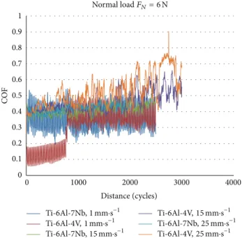
(2) Influence of Speed. Figures14–16represent the influence of applied load to the evolution of the friction coefficient of Ti-6Al-7Nb and Ti-6Al-4V alloy under different loads and sliding speeds. It is seen that the mean coefficient of samples displayed a lower value at 1 mm⋅s−1, and then it sharply
increased to the average value with increasing of sliding speed as shown inFigure 17.
The contact pressure calculated has the same value (690, 870, and 1031 MPa) for both alloy at applied loads, respec-tively, and alternative movement speed.
Table 6: Volumetric wear rate (mm3N−1⋅mm−1) of Ti-6Al-7Nb and Ti-6Al-4V under different conditions.
Load/N
Sliding speed
1 mm⋅s−1 15 mm⋅s−1 25 mm⋅s−1
Ti-6Al-4V Ti-6Al-7NB Ti-6Al-4V Ti-6Al-7NB Ti-6Al-4V Ti-6Al-7NB
3 N 5.45 × 10⁻³ 5.48 × 10⁻³ 22.35 × 10⁻³ 22.06 × 10⁻³ 27.32 × 10⁻³ 31,38×10⁻³ 6 N 9.53 × 10⁻³ 9.64 × 10⁻³ 37.98 × 10⁻³ 38.1 × 10⁻³ 42.15 × 10⁻³ 45.28 × 10⁻³ 10 N 12.08 × 10⁻³ 13.12 × 10⁻³ 51.55 × 10⁻³ 57.35 × 10⁻³ 54.21 × 10⁻³ 57.62 × 10⁻³ 0 0.1 0.2 0.3 0.4 0.5 0.6 0.7 0.8 0.9 0 1000 2000 3000 4000 CO F Distance (cycles) Ti-6Al-7Nb, 1 mm·s−1 Ti-6Al-4V, 1 mm·s−1 Ti-6Al-7Nb, 15 mm·s−1 Ti-6Al-4V, 15 mm·s−1 Ti-6Al-7Nb, 25 mm·s−1 Ti-6Al-4V, 25 mm·s−1 Normal loadFN= 3 N
Figure 14: Friction coefficient of titanium alloys versus sliding distance under different sliding speed at 3 N.
0 0.1 0.2 0.3 0.4 0.5 0.6 0.7 0.8 0.9 1 0 1000 2000 3000 4000 CO F Distance (cycles) Ti-6Al-7Nb, 1 mm·s−1 Ti-6Al-4V, 1 mm·s−1 Ti-6Al-7Nb, 15 mm·s−1 Ti-6Al-4V, 15 mm·s−1 Ti-6Al-7Nb, 25 mm·s−1 Ti-6Al-4V, 25 mm·s−1 Normal loadFN= 6 N
Figure 15: Friction coefficient of titanium alloys versus sliding distance under different sliding speeds at 6 N.
0 0.1 0.2 0.3 0.4 0.5 0.6 0.7 0 1000 2000 3000 4000 CO F Distance (cycles) Ti-6Al-7Nb, 1 mm·s−1 Ti-6Al-4V, 1 mm·s−1 Ti-6Al-7Nb, 15 mm·s−1 Ti-6Al-4V, 15 mm·s−1 Ti-6Al-7Nb, 25 mm·s−1 Ti-6Al-4V, 25 mm·s−1 Normal loadFN= 10 N
Figure 16: Friction coefficient of titanium alloys versus sliding distance under different sliding speeds at 10 N.
3.2.3. Wear Behavior. The volumetric wear rate (Table 6) was calculated using the mechanical profilometer. A 100Cr6 steel ball did the grinding from the sample surface; that is, abrasive wear occurred on the surface and this is illustrated in Figures
18and19. Volumetric wear was determined as 5.45× 10⁻³, 9.53 × 10⁻³and 12.08× 10⁻³mm3N−1⋅mm−1for the Ti-6Al-4V and 5.48× 10⁻³, 9.64× 10⁻³, and 13.12× 10⁻³at 1 mm⋅s−1 sliding speed under load 3, 6, and 10 N, respectively, for the Ti-6Al-7Nb. Finally, the volumetric wear was the same (convergent values) for both the sliding speeds 15 mm⋅s−1and 25 mm⋅s−1
between 22.06× 10⁻³and 57× 10−3mm3N−1⋅mm−1for both samples.Table 6provides the wear volume of the investigated alloys as a function of the sliding speed. The volumetric wear data reveal that the volume loss, irrespective of alloy composition and microstructure, increases as the sliding speed increases.
4. Discussion
4.1. Friction Behavior. The results of the hardness testing
show that Ti-6Al-4V alloy is characterized with higher hardness than Ti-6Al-7Nb. Dependence between wear char-acteristics and hardness was reported earlier and it was observed that wear value decreased with hardness increase
0 0.1 0.2 0.3 0.4 0.5 0.6 Ti -6 Al-7Nb Ti -6 Al-4V Ti -6 Al-7Nb Ti -6 Al-4V Ti -6 Al-7Nb T i-6Al-4V CO F 1 mm·s−1 15 mm·s−1 25 mm·s−1 3 N 6 N 10 N
Figure 17: Mean coefficient of friction of titanium alloys under different conditions of loads and sliding speeds.
[27]. When the properties of titanium alloy were evaluated by parameters obtained from indentation depth, depth was found to decrease with increasing content of impurities [27]. The change in depth value is caused by the effect of yield strength [28] and flow stress [29]. The differences in weight loss and worn surface characteristics among the three metals can be partially attributed to the differences in hardness and the deformation process associated with microstructural characteristics. In addition, there are other factors which influence material wear characteristics. Wear particles have an influence by a surface-damage mechanism [30], and the surface condition was reported to be influential in the wear characteristics of biomaterials alloys [31]. In order to identify phase constitution, titanium alloys were subjected to X-ray diffraction analysis using CuK𝛼 radiation. Presence of both𝛼 and 𝛽 phases was confirmed, and mostly the peaks corresponding to the𝛼 phase (hexagonal closed packed) and𝛽 phase (body-centered cubic) appeared [32,33]. Microstructure of the Ti-6Al-7Nb alloy exhibits 𝛼 refined two-phase structure consisting of acicular𝛼 phase in prior-𝛽 grains. Strength of the alloy is considered to stem from this refined structure.
4.2. Wear Behavior. The results of the wear volume losses
of the studied alloys are presented in the Table 6us func-tion of sliding speed. The volumetric wear data reveal that the volume loss, irrespective of alloy composition and microstructure, increases as the sliding speed increases. The wear resistance of 6Al-4V alloy is higher than that of Ti-6Al-7Nb alloy. As can be seen fromFigure 8, the weight loss of Ti-6Al-4V is lower than that in the case of Ti-6Al-7Nb alloy.
According to the Archard’s law, the volumetric loss of the material is inversely proportional to the hardness value of the material [24]. This implies that the higher the hardness of the material, the smaller the volume loss. The present alloys exhibit significant difference in hardness values, so that the
experimental sliding wear data correlate well with Archard’s law.
Moreover, its wear substantially increases as the sliding speed is increased. It has been observed, for instance, that, at a sliding speed of 25 mm⋅s−1, the wear loss of the
Ti-6Al-7Nb alloy is about 31.38 × 10⁻³, while 27.32 × 10⁻³ (mm3N−1⋅mm−1) wear loss is observed for Ti-6Al-4V alloy. At higher sliding speeds, the difference in wear loss is even much higher. This can be explained by the fact that, as sliding speed increases, the oxidative wear decreases because of the reduction of the time available for the out-of-contact oxidation [34]. The oxidative wear is characterized by the formation of surface oxide islands which are continuously formed and worn away. If the oxide scales on the worn surface are not sufficiently supported by the underlying strain-hardened material and do not adhere to the substrate, they tend to be continuously fragmented. Therefore, they are not protective and the resulting wear is severe. Since the surface of fixed specimens in the present investigation is under continuous contact, one of the reasons for poor wear resistance of investigated alloys is their inability to form protective oxide layer during wear. Although the Ti-based alloys exposed to oxidative environment rapidly form an oxide layer on the surface due to their high reactivity, it’s subsequent removal during the sliding contact is the reason for the interaction between the tribological pair surfaces. The effect of sliding speed on the weight loss of all materials is presented inFigure 8. The estimated values of wear rates indicate that at any sliding speed the wear rates of Ti-6Al-7Nb, Ti-6Al-4V, and ceramic alloys are in decreasing order.
The morphological analysis of the wear tracks confirms the above results. The SEM micrographs presented in Figures
18 and 19 show the typical worn surface morphologies of the specimens tested at the lowest and highest sliding speed. The morphologies of the specimens worn at the intermediate sliding speed are not shown because they show intermediate characteristics between these two extremes. On the worn surfaces of both alloys, evidences of abrasion wear can be detected in all tested specimens.
Continuous sliding marks with plastically deformed grooves and ridges are seen on the wear tracks independently of the sliding speed. However, the extent of plastic defor-mation or “ploughing” is found to be smaller in the case of the Ti-6Al-7Nb alloy (Figures19(a)and19(b)). Layers with consistent plastic deformations are relatively smooth at all evaluated speeds (Figure 19). Only the shallow wear grooves that resulted from the penetrating of hard rigid abrasives and subsequent scratching of the specimen surface by the penetrated abrasives can be observed. The penetration depth depends on the relative hardness of the abrasive with respect to the specimen surface hardness. As the hardness of the Ti-6Al-4V alloy is higher than that of the Ti-6Al-7Nb alloy it is expected that the depth of penetration of the abrasive in the Ti-6Al-4V surface is less. This results in less material removal from the surface due to ploughing action and smaller extent of plastic flow in the case of Ti-6Al-4V. Thus, Ti-6Al-4V alloy exhibits significantly less wear rate as compared to the Ti-6Al-7Nb alloy.
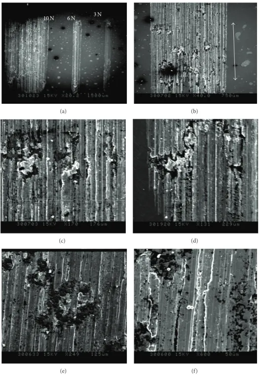
3 N 6 N 10 N (a) (b) (c) (d) (e) (f)
Figure 18: SEM micrographs of circular wear marks on Ti-6Al-4V sample after the friction test (severe deformation and plastic flow). Arrows indicate the sliding direction.
The SEM examination also shows that at least two wear mechanisms are operative in these alloys. Existence of the flakes removed from the contact surface by delamination of material strongly suggests the occurrence of adhesive wear. During sliding, the contacting asperities experience an incremental plastic deformation, which accumulates during repeated contacts [35]. When a critical value of the accumu-lated plastic strain is attained, cracks nucleate below the sur-face and propagate parallel to the sursur-face. As a consequence,
flakes of material are detached from the surface by adhesion to the counterpart. Some of transferred material is lost, but some is reembedded and smeared over the contact surface. In this theory of delamination [35], successively discussed and implemented by numerous authors, it is supposed that a critical plastic strain is given by the ductility of the material. Titanium and its alloys are chemically active and have a high ductility, giving rise to the strong tendency to adhesion [36]. Therefore, the adhesive strength of the junctions formed is
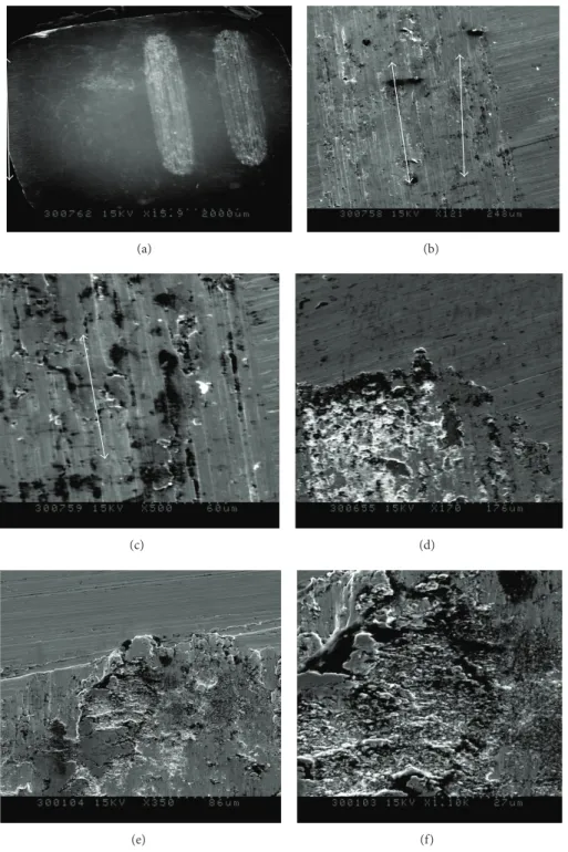
(a) (b)
(c) (d)
(e) (f)
Figure 19: SEM micrographs circular wear marks on Ti-6Al-7Nb sample after the friction test (severe deformation and plastic flow). Arrows indicate the sliding direction.
usually much higher than the strength of Ti alloy and such junctions will rupture within the weaker Ti asperities, which accounts for the many craters on the worn surface of Ti alloy. The removal of materials by adhesion is related to large wear loss and it appears that wear rate is determined by the contribution of adhesive wear to total wear.
SEM micrographs presented inFigure 19show the worn surfaces of Ti-6Al-7Nb alloy. It is evident that fracture on
a much larger scale is occurred and that large flakes are removed from the surface. Detailed investigation of delam-inated regions reveals ridges and cracks perpendicular to the sliding direction. Smeared areas can also be easily detected on the worn surfaces. These features indicate that the wear occurs predominantly by adhesion. In this case, the adhesion overlaps the abrasion and accelerates the wear of the Ti-6Al-7Nb alloy. Occurrence of delamination is more prominent
when wear tests are carried out at higher sliding speeds (Figures19(e)and19(f)). The same behavior was observed by Manivasagam et al. [37].
The other factor contributing to the observed wear behavior may be the strain hardening. Namely, sliding wear processes of ductile materials may produce large amounts of plastic deformation in the material layers adjacent to contact surfaces [38,39].
5. Conclusions
Wear characteristics of high-strength 6Al-7Nb and Ti-6Al-4V alloys were evaluated in a wear test simulating the friction for total hip prosthesis application. The oscillating friction and wear resistance examinations have been carried out in ambient air with oscillating tribotester in accordance with the standards ISO 7148, ASTM G99-95a, and ASTM G133-95. On the one hand, the friction and wear tests were carried out to see the type of wear and to quantify the weight loss and, on the other hand, to see the variation in the friction coefficient of the studied couples under different conditions. The following observations and conclusions were obtained.
(1) The wear resistance of Ti-6Al-7Nb alloys with two-phase 𝛼 + 𝛽 microstructure is substantially lower than that of the Ti-6Al-4V alloy with higher hardness tested under the same testing conditions. The extent of wear is smallest for Ti-6Al-4V with highest hard-ness.
(2) The coefficient friction of both alloys increases with the sliding speed increase. However, Ti-6Al-7Nb alloy shows no significant variation of coefficient of friction with sliding speed variation, while in the case of Ti-6Al-4V alloy the coefficient of Ti-6Al-4V alloy increases linearly with increasing sliding speed. This behavior can be attributed to the predominant wear mechanism.
(3) The two Ti alloys had similar friction and wear performance, although their grain structures and compositions are different.
(4) Large frictional fluctuations occurred, probably as a result of formation and periodic, localized fracture of a transfer layer.
(5) Higher friction coefficient with more distinct value fluctuation and higher wear rate was observed at the higher siding peed.
(6) For both investigated alloys and under all investigated conditions, the friction coefficient firstly decreases and then increases as a function of the sliding distance. The evolution of the friction coefficient is related to the composition of the worn surfaces. (7) The Ti-6Al-4V alloy wear mechanism transforms
from ploughing and peeling off wear at low sliding speeds to plastic deformation and adhesive wear at elevated speed.
(8) The weight loss, which quantifies the wear of a soft body slipping on a hard surface, is proportional not
only to the distance from the slip but also to the normal load applied.
(9) The sliding speed has for a principal effect to act on the temperature of the contact zone. Going beyond a critical speed involves the surface fusion of the most fusible body.
(10) The increase in the temperature of the contact zone with the increase of the sliding speed induces struc-ture transformations and increases the reactivity of contact surfaces with respect to the environment, that is, oxidation in the presence of air. Above a certain temperature and thus for sliding speeds higher than a breaking value, the oxide film, resulting from a permanent oxidation, is reconstituted with the fur as it is destroyed by wear.
Conflict of Interests
The authors declare that there is no conflict of interests regarding the publication of this paper.
Acknowledgments
This work was realized in collaboration with the laboratory of MSMP Material surfaces and Processing Materials, Art et M´etiers Paris tech-Lille France. The authors wish to thank the director of the Laboratory, for kindly supplying the TiAlV Metal bars and TiAlNb femoral stem. The authors are also grateful to the professor ALAIN IOST, for Permitting to utilize the SEM and tribotester facility.
References
[1] Z.-B. Cai, G.-A. Zhang, Y.-K. Zhu, M.-X. Shen, L.-P. Wang, and M.-H. Zhu, “Torsional fretting wear of a biomedical Ti6Al7Nb alloy for nitrogen ion implantation in bovine serum,” Tribology
International, vol. 59, pp. 312–320, 2013.
[2] N. Masahashi, Y. Mizukoshi, S. Semboshi, K. Ohmura, and S. Hanada, “Photo-induced properties of anodic oxide films on Ti6Al4V,” Thin Solid Films, vol. 520, no. 15, pp. 4956–4964, 2012. [3] J. Cheng, J. Yang, X. Zhang et al., “High temperature tribological behavior of a Ti-46Al-2Cr-2Nb intermetallics,” Intermetallics, vol. 31, pp. 120–126, 2012.
[4] L. Bolzoni, E. M. Ruiz-Navas, E. Neubauer, and E. Gordo, “Mechanical properties and microstructural evolution of vac-uum hot-pressed titanium and Ti-6Al-7Nb alloy,” Journal of the
Mechanical Behavior of Biomedical Materials, vol. 9, pp. 91–99,
2012.
[5] K. Ida, Y. Tani, S. Tsutsumi et al., “Clinical application of pure titanium crowns,” Dental Materials Journal, vol. 4, no. 2, pp. 191– 195, 1985.
[6] B. Bergman, C. Bessing, G. Ericson, P. Lundquist, H. Nilson, and M. Andersson, “A 2-year follow-up study of titanium crowns,”
Acta Odontologica Scandinavica, vol. 48, no. 2, pp. 113–117, 1990.
[7] T. Kawazoe and K. Suese, “Clinical application of titanium crowns,” Journal of Medical and Dental Sciences, vol. 30, no. 3, pp. 317–328, 1989.
[8] A. Kuroiwa and Y. Igarashi, “Application of pure titanium to metal framework,” The Journal of the Japan Prosthodontic
Society, vol. 42, pp. 547–558, 1998.
[9] M. A. Khan, R. L. Williams, and D. F. Williams, “In-vitro corro-sion and wear of titanium alloys in the biological environment,”
Biomaterials, vol. 17, no. 22, pp. 2117–2126, 1996.
[10] A. Guitar, G. Vegan, and M. I. Luppo, “Microstructure and tensile properties after thermo hydrogen processing of Ti-6Al-4V,” Journal of the Mechanical Behavior of Biomedical Materials, vol. 2, no. 2, pp. 156–163, 2009.
[11] C. R. Ramos-Saenz, P. A. Sundaram, and N. Diffoot-Carlo, “Tribological properties of Ti-based alloys in a simulated bone-implant interface with Ringer's solution at fretting contacts,”
Journal of the Mechanical Behavior of Biomedical Materials, vol.
3, no. 8, pp. 549–558, 2010.
[12] R. C. Browne, “Vanadium poisoning from gas turbines,” The
British Journal of Industrial Medicine, vol. 12, no. 1, pp. 57–59,
1955.
[13] S. G. Sjoberg, “Vanadium dust, chronic bronchitis and possible risk of emphysema: a follow-up investigation of workers at a vanadium factory,” Acta Medica Scandinavica, vol. 154, pp. 381– 386, 1956.
[14] G. B. van der Voet, E. Marani, S. Tio, and F. A. de Wolff, “Aluminium neurotoxicity,” in Histo- and Cyto-Chemistry as a
Tool in Environmental Toxicology, W. Graumann and J. Drukker,
Eds., pp. 235–242, Fisher, Stuttgart, Germany, 1991.
[15] D. R. C. Mc Lachlan, G. Farnees, and I. T. Galin, Biological
Aspects of Metals and Metal Related Diseases, Ravan Press, New
York, NY, USA, 1983.
[16] D. Scharnweber, “Degradation (in vitro-in vivo corrosion),” in
Metals as Biomaterials, J. A. Helsen and H. J. Breme, Eds., pp.
101–151, John Wiley & Sons, London, UK, 1998.
[17] M. F. Lopez, L. Soriano, F. J. Palomares et al., “Soft x-ray absorption spectroscopy study of passive and oxide layers of titanium alloys,” Surface and Interface Analysis, vol. 33, pp. 570– 579, 2002.
[18] C. Morant, M. F. L´opez, A. Guti´errez, and J. A. Jim´enez, “AFM and SEM characterization of non-toxic vanadium-free Ti alloys used as biomaterials,” Applied Surface Science, vol. 220, no. 1–4, pp. 79–87, 2003.
[19] M. Fellah, O. Assala, M. Laba¨ız, L. Dekhil, and A. Iost, “Friction and wear behavior of Ti-6Al-7Nb biomaterial alloy,” Journal of
Biomaterials & Nanobiotechnology, vol. 4, no. 4, pp. 374–384,
2013.
[20] M. F. Semlitsch, H. Weber, R. M. Streicher, and R. Sch¨on, “Joint replacement components made of hot-forged and surface-treated Ti-6Al-7Nb alloy,” Biomaterials, vol. 13, no. 11, pp. 781– 788, 1992.
[21] E. Kobayashi, T. J. Wang, H. Doi, T. Yoneyama, and H. Hamanaka, “Mechanical properties and corrosion resistance of Ti-6Al-7Nb alloy dental castings,” Journal of Materials Science:
Materials in Medicine, vol. 9, no. 10, pp. 567–574, 1998.
[22] E. Confortoa, B.-O. Aronssonb, A. Salitoc, C. Crestoud, and D. Caillard, “Rough surfaces of titanium and titanium alloys for implants and prostheses,” Materials Science and Engineering C, vol. 24, no. 5, pp. 611–618, 2004.
[23] Norme Internationale, “Implants chirurgicaux: proth`eses par-tielles et totales de l’articulation de la hanche—Partie 2: surfaces articulaires constitu´ees de mat´eriaux m´etalliques, c´eramiques et plastiques,” ISO 7206-2:1996, 1996.
[24] J. F. Archard, “Contact and rubbing of flat surfaces,” Journal of
Applied Physics, vol. 24, no. 8, pp. 981–988, 1953.
[25] M. Fellah, M. Laba¨ız, O. Assala, and A. Iost, “Tribological behavior of friction couple: metal/ceramic (used for head of total hip replacement),” in Advances in Bioceramics and Porous
Ceramics VI, pp. 45–57, 2014.
[26] L. Avril, Elaboration de revˆetements sur acier inoxydable
simula-tion de la fusion par irradiasimula-tion laser caract´erisasimula-tion structurale, m´ecanique et tribologique [th`ese], Ecole Nationale Superieure
D’arts et Metiers, 2003.
[27] T. Yoneyama, H. Doi, E. Kobayashi, T. Nakano, and H. Hamanaka, “Deformation property of titanium and dental alloys in an indentation test,” Dentistry in Japan, vol. 33, pp. 92– 96, 1997.
[28] A. G. Atkins and D. Tabor, “Plastic indentation in metals with cones,” Journal of the Mechanics and Physics of Solids, vol. 13, no. 3, pp. 149–164, 1965.
[29] G. Sundararajan and Y. Tirupataiah, “The hardness-flow stress correlation in metallic materials,” Bulletin of Materials Science, vol. 17, no. 6, pp. 747–770, 1994.
[30] R. A. Buchanan, E. D. Rigney Jr., and J. M. Williams, “Wear-accelerated corrosion of Ti-6Al-4V and nitrogen-ion-implanted Ti-6Al-4V: mechanisms and influence of fixed-stress magnitude,” Journal of Biomedical Materials Research, vol. 21, pp. 367–377, 1987.
[31] A. U. J. Yap, L. F. K. L. Ong, S. H. Teoh, and G. W. Hastings, “Comparative wear ranking of dental restoratives with the BIOMAT wear simulator,” Journal of Oral Rehabilitation, vol. 26, no. 3, pp. 228–235, 1999.
[32] H. Doi, T. Yoneyama, E. Kobayashi, and H. Hamanaka, “Mechanical properties and corrosion resistance of Ti-5Al-13Ta alloy castings,” The Journal of the Japanese Society for Dental
Materials and Devices, vol. 17, pp. 247–245, 1998.
[33] D. Iijima, T. Yoneyama, H. Doi, H. Hamanaka, and N. Kurosaki, “Wear properties of Ti and Ti-6Al-7Nb castings for dental prostheses,” Biomaterials, vol. 24, no. 8, pp. 1519–1524, 2003. [34] G. Straffelini and A. Molinari, “Dry sliding wear of Ti-6Al-4V
alloy as influenced by the counterface and sliding conditions,”
Wear, vol. 236, no. 1-2, pp. 328–338, 1999.
[35] N. P. Suh, “Update on the delamination theory of wear,” in
Fundamentals of Friction and Wear of Materials, D. A. Rigney,
Ed., p. 43, ASM, Materials Park, Ohio, USA, 1980.
[36] H. Dong and T. Bell, “Enhanced wear resistance of titanium surfaces by a new thermal oxidation treatment,” Wear, vol. 238, no. 2, pp. 131–137, 2000.
[37] G. Manivasagam, U. K. Mudali, R. Asokamani, and B. Raj, “Corrosion and microstructural aspects of titanium and its alloys as orthopaedic devices,” Corrosion Reviews, vol. 21, no. 2-3, pp. 125–159, 2003.
[38] M. Fellah, M. Laba¨ız, O. Assala, A. Iost, and L. Dekhil, “Tri-bological behaviour of AISI 316L stainless steel for biomedical applications,” Tribology—Materials, Surfaces and Interfaces, vol. 7, no. 3, pp. 135–149, 2013.
[39] I. Cvijovic-Alagic, Z. Cvijovic, S. Mitrovic, V. Panic, and M. Rakin, “Wear and corrosion behavior of 13Nb-13Zr and Ti-6Al-4V alloys in simulated physiological solution,” Corrosion