Science Arts & Métiers (SAM)
is an open access repository that collects the work of Arts et Métiers Institute of
Technology researchers and makes it freely available over the web where possible.
This is an author-deposited version published in: https://sam.ensam.eu Handle ID: .http://hdl.handle.net/10985/9947
To cite this version :
Phuoc Hoa TRUONG, Damien FLIELLER, Ngac Ky NGUYEN, Jean MERCKLE - Optimal Efficiency Control of Synchronous Reluctance Motors-based ANN Considering Cross Magnetic Saturation and Iron Loss - In: Conférence IECON 2015, Japon, 2015-11 - IECON 2015 - 2015
Any correspondence concerning this service should be sent to the repository Administrator : archiveouverte@ensam.eu
Optimal Efficiency Control of Synchronous
Reluctance Motors-based ANN Considering Cross
Magnetic Saturation and Iron Loss
Phuoc Hoa Truong
1, Damien Flieller
2, Ngac Ky Nguyen
3, Jean Mercklé
11
MIPS Laboratory - University of Haute Alsace, 4 Rue des Frères Lumière, 68093 Mulhouse - France. [phuoc-hoa.truong, jean.merckle]@uha.fr
2
GREEN Laboratory - INSA de Strasbourg, 24 Boulevard de la Victoire, 67084 Strasbourg - France. damien.flieller@insa-strasbourg.fr
3
L2EP Laboratory –Arts et Métiers ParisTech – CER de Lille, 8 Boulevard Louis XIV, 59046 Lille- France. NgacKy.NGUYEN@ensam.eu
Abstract— This paper presents a new idea by using the Artificial Neural Networks (ANNs) for estimating the parameters of the machine which achieving the maximum efficiency of the Synchronous Reluctance Motor (SynRM). This model take into consideration the magnetic saturation, cross-coupling and iron loss. With Finite Element Analysis (FEA), the characteristics of the SynRM including inductances and iron loss resistance are determined. Because of the non-linear characteristics, an ANN trained off-line, is then proposed to obtain the d-q inductances and iron loss resistance from Id,Iq currents and the speed. After
learning process, an analytical expression of the optimal currents is given thanks to Lagrange optimization. Therefore, the optimal currents will be obtained online in real time. This method can be achieved with maximum efficiency and high-precision torque control. Simulation and experimental results are presented to confirm the validity of the proposed method.
Index Terms— Synchronous Reluctance Motor, Optimal Efficiency, Finite Element Analysis, Optimal Currents, Lagrange Optimization, Artificial Neural Networks.
I. INTRODUCTION
ynchronous reluctance motor (SynRM) has received much attention for many applications in recent years due to its simplicity of structure, low manufacturing cost and rugged construction [1-2]. Many authors proposed different methods for improving the efficiency this kind of machine. In general, two major approaches can be identified.
The first one uses a search algorithm and is called search controller (SC) method [3-4]. The electrical input power is measured and minimized by different algorithms. The authors in [3] proposed a method for optimum-efficiency controller of a SynRM drive by adding a small amount of perturbation to the d-axis current reference for the purpose of searching a minimum input power. However, the convergence of this method is very low and there is torque ripple in steady state. The works presented in [4] minimizes the input power with a search controller using Fibonacci search algorithm. It searches the optimal reference value of the d-axis stator current for which the input power is minimum. The optimal efficiency
maybe not reached if the initial working point is far from the optimal point.
The second approach, called loss model controller (LMC), is based on a loss model of the motor [5-16]. The optimal currents are generated from the equations of the machine losses. This approach is more often used in industrial drive systems because of the control stability and current pulsation reduction [13]. In [6-7], the loss-model are introduced for determining the optimal d-axis component of the stator current which minimizing the power losses. Based on input–output linearization, the authors in [8-9] proposed the methods to obtain the constant torque and minimize the losses. However, this method contain the drawback including complexity in real-time constraints. In [10], an ANN was trained online to map the optimal current ratio and an extended Kalman filter in [11] is proposed by the authors to estimate the parameter of the SynRM in order to achieve the optimal efficiency of this kind this machine. In [12], a high-efficiency control based on fuzzy logic is reported. However, the fuzzy logic control requires the experiences of the designer.
This paper presents an investigation of Artificial Neural Networks (ANNs) for optimal efficiency control of Synchronous Reluctance Motors including magnetic saturation, cross-coupling and iron loss. The proposed method can determine the optimal d- and q-axis currents quickly thanks to Lagrange optimization. This method is capable of both maximum efficiency and also realize high-precision torque control. An ANN is proposed to estimate the d-q inductances and iron loss resistance which deriving the maximum efficiency immediately. With an ANN, we can improve the accuracy of the parameters estimation when using an approximation integrator in [13]. Moreover, it can be replace the look-up table in [14] to reduce the large memory space when the database of the machine parameters is very large. The comparisons of the efficiency between the conventional and the proposed method are presented by the simulation and experimental results to confirm the validity of the proposed method.
This paper is organized as follows: The Lagrange optimization to obtain the optimal currents is presented in Section II. Section III presents the investigation of ANN for the parameters estimation. Simulation and experimental results are shown in Section IV and V respectively. Finally, the conclusions are given in Section VI.
II. OPTIMALCURRENTSBASEDONLAGRANGE OPTIMIZATION
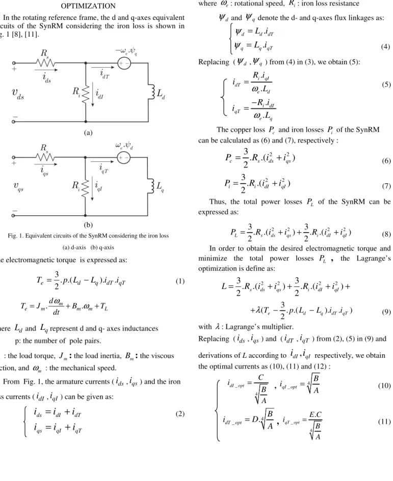
In the rotating reference frame, the d and q-axes equivalent circuits of the SynRM considering the iron loss is shown in Fig. 1 [8], [11].
(a)
(b)
Fig. 1. Equivalent circuits of the SynRM considering the iron loss (a) d-axis (b) q-axis
The electromagnetic torque is expressed as:
3
. .(
).
.
2
e d q dT qTT
=
p L
−
L
i
i
(1) or . m . e m m m L d T J B T dtω
ω
= + +where
L
d andL
qrepresent d and q- axes inductancesp: the number of pole pairs.
L
T
: the load torque,J
m:
the load inertia,B
m:
the viscous friction, andω
m : the mechanical speed.From Fig. 1, the armature currents (
i
ds,i
qs) and the ironloss currents (
i
dI ,i
qI ) can be given as:ds dI dT
i
=
i
+
i
(2)
i
qs=
i
qI+
i
qTIn the steady state, the currents can be expressed as:
.
e dI q ii
R
ω
ψ
−
=
(3) qI e.
d ii
R
ω
ψ
=
where
ω
e: rotational speed,R
i: iron loss resistance
ψ
d andψ
q denote the d- and q-axes flux linkages as:ψ
d=
L i
d.
dTψ
q=
L i
q.
qT(4)
Replacing (
ψ
d ,ψ
q ) from (4) in (3), we obtain (5):.
.
i qI dT e dR i
i
L
ω
=
(5)
.
.
i dI qT e qR i
i
L
ω
−
=
The copper loss
P
c and iron lossesP
i of the SynRM can be calculated as (6) and (7), respectively :2 2
3
.
.(
)
2
c s ds qsP
=
R
i
+
i
(6) 2 23
. .(
)
2
i i dI qIP
=
R i
+
i
(7)Thus, the total power losses
P
L of the SynRM can beexpressed as:
3
.
.(
2 2)
3
. .(
2 2)
2
2
L s ds qs i dI qI
P
=
R
i
+
i
+
R i
+
i
(8) In order to obtain the desired electromagnetic torque and minimize the total power lossesP
L,
the Lagrange’soptimization is define as:
2 2 2 2
3
3
.
.(
)
. .(
)
2
s ds qs2
i dI qIL
=
R
i
+
i
+
R i
+
i
+
3
(
. .(
).
.
)
2
e d q dT qTT
p L
L
i
i
λ
+
−
−
(9) with λ: Lagrange’s multiplier.
Replacing (
i
ds,i
qs) and (i
dT ,i
qT ) from (2), (5) in (9) andderivations of L according to
i
dI,
i
qI respectively, we obtainthe optimal currents as (10), (11) and (12) :
_ 4 dI opt C i B A = , 4 _ qI opt
B
i
A
=
(10) dT_opt.
4B
i
D
A
=
,
_ 4 . qT opt E C i B A = (11)ds_ref ds_opt
.
4B
i
i
D
A
=
=
4 C B A + (12) _ _ 4.
qs ref qs optE C
i
i
B
A
=
=
4B
A
+
with 2 2 23
.(
.
)
2
.
i s s i e dR
A
R
R
R
L
ω
=
+
+
2 2 2 2 2 2
.
.
.
2
.(
) (
.
)
3
.(
).
.
e e d q i s s i d q i e dT
L L
R
B
R
R
R
p L
L
R
L
ω
ω
=
+
+
−
2 2 2. . . . 3. .( ). e e d q d q i T L L C p L L R
ω
= − −,
.
i e dR
D
L
ω
=
,
.
i e qR
E
L
ω
−
=
Finally, three phase optimal currents will be obtained by:
_ _ _ _ _
(
).
a opt ds opt b opt qs opt c opti
i
i
p
i
i
θ
= P
(13)where
P
(
p
θ
)
: Park’s transformation is defined ascos( ) sin( ) 2 2 2 ( ) cos( ) sin( ) 3 3 3 2 2 cos( ) sin( ) 3 3 p p p p p p p θ θ π π θ θ θ π π θ θ − = ⋅ − − − + − + P (14)
The output power
P
out and the efficiency of the SynRMdrive
η
are expressed as :.100%
out out LP
P
P
η
=
+
(15) III. INVESTIGATIONOFARTIFICIALNEURAL NETWORKSFORTHEPARAMETERSESTIMATION
This section presents the investigation of Artificial Neural Networks to estimate the parameters Ld,L Rq, iof the SynRM including magnetic saturation and cross-coupling.
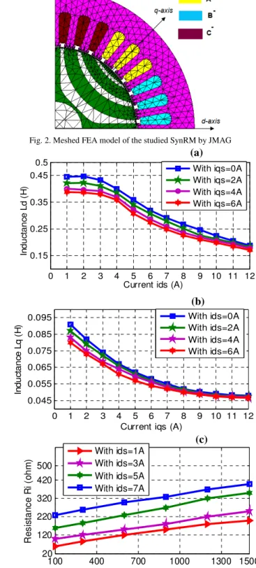
Fig. 2 shows the meshed FEA model of the studied SynRM when using JMAG software in order to calculate the parameters of the machine. The inductances Ld,Lqand iron loss resistance Ri obtained with FEA is shown in Fig. 3. As can be seen, when the currents ids and iqs increase, the inductanceLd,L will be decreased because of the magnetic q saturation and cross-coupling [13], [15]. Fig 3c shows the influence of the iron loss resistance by the current
i
ds and the speed [8].Fig. 2. Meshed FEA model of the studied SynRM by JMAG
0 1 2 3 4 5 6 7 8 9 10 11 12 0.15 0.25 0.35 0.45 0.5
Current ids (A)
In d u ct a n ce L d ( H ) With iqs=0A With iqs=2A With iqs=4A With iqs=6A 0 1 2 3 4 5 6 7 8 9 10 11 12 0.045 0.055 0.065 0.075 0.085 0.095
Current iqs (A)
In d u ct a n ce L q ( H
) With ids=0AWith ids=2A
With ids=4A With ids=6A 100 400 700 1000 1300 1500 20 120 220 320 420 500 Speed (rpm) R e s is ta n c e R i (o h m
) With ids=1AWith ids=3A
With ids=5A With ids=7A
Fig. 3. Parameters of the machine obtained with FEA (a) Inductance Ld(b) Inductance Lq (c) Iron loss resistance Ri
The parameters of the machine including Ld,L Rq, i obtained from FEA were used to train the Neural Network is shown in the Fig.4. This ANN include 3 inputs
i
ds,
i
qs,
ω
rand 3 outputs Ld_es,Lq es_ ,Ri es_ .(a)
(b)
Fig. 4. Neural Networks to estimate Ld,L Rq, i
A two-layer network is used for implementing this net. The training algorithm is Levenberg –Marquardt with trainlm function. The squared error acceptable for training is 10-4.
Number of neurons of the 1st layer is 4 logsig neurons. The 2nd layer has 3 purelin neurons. So, the total number of neurons is 7. The weights of the ANN are updated using an iterative linear LMS (Least Mean Square) algorithm [17] in order to minimize the error between the actual value
, ,
d q i
L L R and the estimated value Ld_es,Lq es_ ,Ri es_ . The weights wor v are adjusted according to:
( 1) ( ) . ( ). ( )i
w k+ =w k +
η
e k x k (16) where xis the input vector (i
ds,
i
qs,
ω
r),η
is a learning rate,e
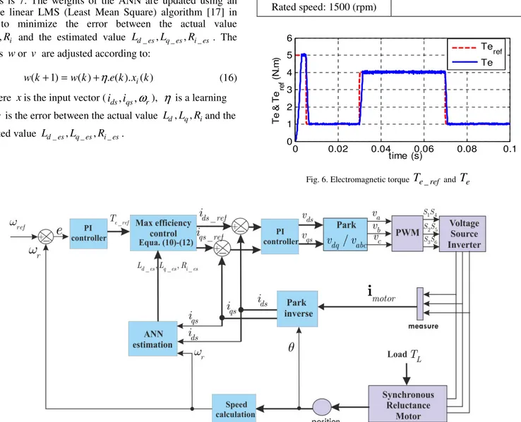
is the error between the actual value Ld,L Rq, iand the estimated value Ld_es,Lq es_ ,Ri es_ .IV. SIMULATIONOFTHEPROPOSEDMETHOD To confirm the validity of the proposed method in the previous sections, a Matlab/Simulink program is used to simulate. The optimal efficiency control of the SynRM with parameters estimation by ANN is presented in Fig. 5. The parameters of the machine for simulation and experimental results are shown in Table I. In this simulation, the reference speed is fixed at 500 (rpm). By changing the load torque, the currents in d-q-axes has been changed. The parameters of the machine will be estimated by ANN to achieve with maximum efficiency.
Table I. Parameters of the SynRM under simulation and experimental test
Rated power: P=1.1 (Kw) 2
0.002( ) m
J = kgm ,
Rated current: In rms− =3A Pole pairs number: p=2 Resistance: Rs =6.2( )Ω Rated torque:
7( . ) N T = N m Rated speed: 1500 (rpm) 0 0.02 0.04 0.06 0.08 0.1 0 1 2 3 4 5 6 time (s) T e & T e re f ( N .m ) Teref Te
Fig. 6. Electromagnetic torque
T
e ref_ andT
e0 0.02 0.04 0.06 0.08 0.1 0 0.5 1 1.5 2 2.5 time (s) id s & id s re f ( A ) idsref ids 0 0.02 0.04 0.06 0.08 0.1 0 1 2 3 time (s) iq s & iq sre f ( A ) iqsref iqs
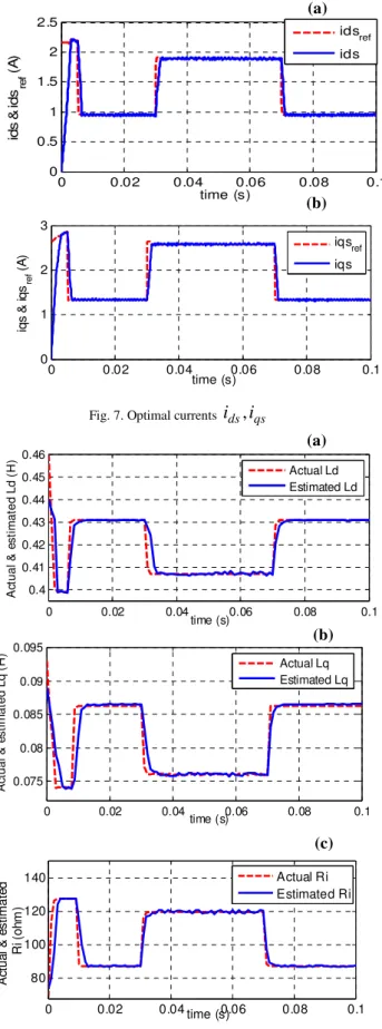
Fig. 7. Optimal currents
i
ds,
i
qs0 0.02 0.04 0.06 0.08 0.1 0.4 0.41 0.42 0.43 0.44 0.45 0.46 time (s) A ct u a l & e s ti m a te d L d ( H ) Actual Ld Estimated Ld 0 0.02 0.04 0.06 0.08 0.1 0.075 0.08 0.085 0.09 0.095 time (s) A ct u a l & e s ti m a te d L q ( H ) Actual Lq Estimated Lq 0 0.02 0.04 0.06 0.08 0.1 80 100 120 140 time (s) A ct u a l & e s ti m a te d R i ( o h m ) Actual Ri Estimated Ri
Fig. 8. Parameters estimated by ANN (a) Inductance Ld (b) Inductance Lq (c) Resistance Ri
300 600 900 1200 1500 60 65 70 75 80 85 Speed (rpm) E ff ic ie n c y ( % )
With optimal currents With constant d-axis currrent
Fig. 9. Efficiency comparison of the proposed with conventional method
Fig. 6 and Fig. 7 show the electromagnetic torque and optimal currents ids,i respectively with the proposed method. qs We can observer that the torque and the optimal currents are good regulation.
Fig. 8 is showing the parameters of the machine including , ,
d q i
L L R estimated by ANN. As can be seen, the estimated inductances and the resistance iron loss converge to real values within a short time.The accurate of the parameters estimation is important to achieve maximum efficiency of the machine.
The efficiency comparison at rated load between the proposed and the conventional method (constant d-axis current) is shown in Fig. 9. As can be seen, the efficiency of the proposed method at rated speed is around 83% while the efficiency of conventional one is around 75%. It is obvious that the efficiency when using the optimal currents is superior than the conventional method [8], [11].
In next section, the experimental results will be presented to confirm the validity of the proposed method.
V. EXPERIMENTALRESULTS
The experimental platform is shown in Fig. 10. A three phase machine SynRM is connected to a three-phase voltage source inverter. The machine parameters are given in Table I. The rotor’s position and the stator currents are measured in real time by using an incremental coder and currents sensors thought by the DSPACE 1104. The ANN Controller has been implemented using kit DSPACE 1104 with Matlab/Simulink.
Fig. 10. Experimental platform setup
(a)
(b)
(c) (a)
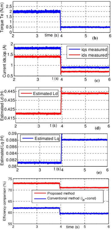
2 3 4 5 6 0 0.5 1 1.5 2 2.5 time (s) T o rq u e T e ( N .m ) 2 3 4 5 6 0.5 1 1.5 2 C u rr e n t id s ,i q s ( A ) t (s) iqs measured ids measured 2 3 4 5 6 0.415 0.425 0.435 0.445 t (s) E st im a te d L d ( H ) Estimated Ld 2 3 4 5 6 0.08 0.082 0.084 0.086 0.088 0.09 t (s) E st im a te d L q ( H ) Estimated Lq 2 3 4 5 6 55 60 65 70 75 time (s) E ff ic ie n c y c o m p a ri so n ( % ) Proposed method
Conventional method (idt=const)
Fig. 11. Experimental results at ωr=70(rad s/ )
Fig.11 shows the experimental results of the proposed method at ωr=70(rad s/ ). We can observer that the good convergence of the ANN for estimating the parameters of the machine and the efficiency of the proposed method is higher about 10% with the conventional one.
VI. CONCLUSIONS
A new idea by using the ANN for estimating the parameters of the machine which can replace an approximation integrator or the look-up table is proposed in this paper. With the proposed method, the optimal currents
will be obtained online in real time which helping to achieve the maximum efficiency and high-precision torque control. The simulation and experimental results clearly show that the efficiency when using the optimal currents is superior than the conventional method. Furthermore, the ANN shows the accurate of the parameters estimation.
REFERENCES
[1] S. Taghavi and P. Pillay, "A Sizing Methodology of the Synchronous Reluctance Motor for Traction Applications," IEEE Journal of Emerging
and Selected Topics in Power Electronics, vol. 2, pp. 329-340, 2014. [2] M. Ferrari, et al., "Design of Synchronous Reluctance Motor for Hybrid
Electric Vehicles," IEEE Transactions on Industry Applications vol. PP, pp. 1-1, 2015.
[3] T. Matsuo, A. El-Antably and T. A. Lipo, "A new control strategy for optimum-efficiency operation of a synchronous reluctance motor," IEEE
Transactions on Industry Applications, vol. 33, pp. 1146-1153, 1997. [4] T. Lubin, H. Razik and A. Rezzoug, "On-line efficiency optimization of
a synchronous reluctance motor," Electric Power Systems Research, vol. 77, pp. 484-493, 2007.
[5] H. F. Hofmann, S. R. Sanders and A.El-Antably, "Stator-flux-oriented vector control of synchronous reluctance Machines with maximized efficiency," IEEE Transactions on Industrial Electronics, vol. 51, pp. 1066-1072, 2004.
[6] I. Kioskeridis and C. Mademlis, "Energy efficiency optimisation in synchronous reluctance motor drives," IEE Proceedings Electric Power
Applications, vol. 150, pp. 201-209, 2003.
[7] C. Mademlis, I. Kioskeridis and N. Margaris, "Optimal efficiency control strategy for interior permanent-magnet synchronous motor drives," IEEE Transactions on Energy Conversion vol. 19, pp. 715-723, 2004.
[8] L. Hyeoun-Dong, K. Seog-Joo and S. Seung-Ki, "Efficiency-optimized direct torque control of synchronous reluctance motor using feedback linearization," IEEE Transactions on Industrial Electronics vol. 46, pp. 192-198, 1999.
[9] H. Abootorabi Zarchi, J.Soltani and G.A. Markadeh "Adaptive Input-Output Feedback-Linearization-Based Torque Control of Synchronous Reluctance Motor Without Mechanical Sensor," IEEE Transactions on
Industrial Electronics vol. 57, pp. 375-384, 2010.
[10] T. Senjyu, T. Shingaki and K. Uezato, "A novel high efficiency drive strategy for synchronous reluctance motors considering iron loss using neural network," 16th Annual IEEE Applied Power Electronics
Conference, vol. 2, pp. 1090-1095, 2001.
[11] T. Senjyu, et al., "High efficiency control of synchronous reluctance motors using extended Kalman filter," IEEE Transactions on Industrial
Electronics, vol. 50, pp. 726-732, 2003.
[12] M. N. Uddin and J. Khastoo, "Fuzzy Logic-Based Efficiency Optimization and High Dynamic Performance of IPMSM Drive System in Both Transient and Steady-State Conditions," IEEE Transactions on
Industry Applications, vol. 50, pp. 4251-4259, 2014.
[13] S. Yamamoto, et al., "Maximum Efficiency Drives of Synchronous Reluctance Motors by a Novel Loss Minimization Controller With Inductance Estimator," IEEE Transactions on Industry Applications, vol. 49, pp. 2543-2551, 2013.
[14] H. Aorith, et al., "A new Loss Minimization Algorithm for Interior Permanent Magnet Synchronous Machine drives," IEEE International
Electric Machines & Drives Conference (IEMDC), pp. 526-533, 12-15 May 2013.
[15] Q. Zengcai, et al., "Minimizing losses of a synchronous reluctance motor drive taking into account core losses and magnetic saturation,"
16th European Conference on Power Electronics and Applications (EPE'14) pp. 1-10, 26-28 Aug 2014.
[16] N. Ronggang, et al., "Maximum Efficiency Per Ampere Control of Permanent-Magnet Synchronous Machines," IEEE Transactions on
Industrial Electronics, vol. 62, pp. 2135-2143, 2015.
[17] B. Widrow and E. Walach, Adaptive Inverse Control. Prentice-Hall, 1996. (a) (b) (c) (d) (e)