This is an author-deposited version published in: https://sam.ensam.eu
Handle ID: .http://hdl.handle.net/10985/13805
To cite this version :
Mario BERMUDEZ GUZMAN, Oleg GOMOZOV, Xavier KESTELYN, Ngac Ky NGUYEN, Eric SEMAIL, Federico BARRERO - Real-time validation of a cascaded model predictive control technique for a five-phase permanent magnet synchronous machine under current and voltage limits - In: ELECTRIMACS 2017, France, 2017-07 - Real-time validation of a cascaded model predictive control technique for a five-phase permanent magnet synchronous machine under current and voltage limits - 2017
R
EAL
-T
IME
V
ALIDATION OF A
C
ASCADED
M
ODEL
P
REDICTIVE
C
ONTROL
T
ECHNIQUE FOR A
F
IVE
-P
HASE
P
ERMANENT
M
AGNET
S
YNCHRONOUS
M
ACHINE
U
NDER
C
URRENT AND
V
OLTAGE
L
IMITS
M. Bermudez
1,2, O. Gomozov
1, X. Kestelyn
1, N. K. Nguyen
1, E. Semail
1, F. Barrero
2 1. Univ. Lille, Centrale Lille, Arts et Métiers ParisTech, HEI, EA 2697 - L2EP Laboratoired’Electrotechnique et d’Electronique de Puissance F-59000 Lille, France.
e-mail: mario.bermudez-guzman@ensam.eu, oleg.gomozov@ensam.eu, xavier.kestelyn@ensam.eu,
ngacky.nguyen@ensam.eu, eric.semail@ensam.eu
2. Departamento de Ingeniería Electrónica, Universidad de Sevilla, Camino de los Descubrimientos s/n, 41092 Sevilla, Spain.
e-mail: fbarrero@us.es
Abstract – Multiphase machines have recently gained importance in the research community for their use in applications where high power density, wide speed range and fault-tolerant capabilities are needed. The optimal control of such drives requires to consider voltage and current constraints imposed by the power converter and the machine itself. If classical three-phase drives have been optimally controlled under such limits for a long time, the same cannot be said in the case of multiphase drives. This paper deals with this issue, where an optimal control technique based on Cascaded Model Predictive Controls (MPC) is presented for a five-phase permanent magnet synchronous machine (PMSM). A Continuous-Control-Set MPC (CCS-MPC) numerically computes optimal current references in real-time in order to exploit the maximum performance for given DC bus voltage and current limits. Then, a Finite-Control-Set MPC (FCS-MPC) is used to carry out the current control in the machine, directly applying the switching state that minimizes a cost function related to the current tracking. Obtained mixed microprocessor-based and FPGA-based real-time simulations prove the interest of the proposal, which ensures the optimal control of the multiphase drive operating under current and voltage constraints.
Keywords – Multiphase drives, Model Predictive Control, current and voltage limits, optimal reference currents.
1.
INTRODUCTİON
Compared to classical three-phase drives, multiphase ones reduce the electrical stresses on machine and power electronic components, since they can manage more power with lower torque pulsation and lower current harmonic content, and have inherent fault-tolerance capabilities [1]. Such advantages make them an ideal candidate for applications where limits can be reached and reliability is of special interest for economical and safety reasons. For example, in traction, power generation or electrical vehicle drives, the high-speed capability of the drive is required and it is often desirable to extract the maximum torque capability over the entire speed range, which depends on the voltage and current constraints of the machine and the voltage source inverter (VSI). Therefore, an optimal control of these machines working under such limits is necessary.
Optimal control of three-phase drives working at their limits is easy to implement. Since only one dq reference frame is used, analytical expressions of optimal reference currents can be easily obtained while respecting the imposed limits. In this case, it is necessary to weak the machine flux (reducing the d-current component) in order to respect the imposed voltage limit, adjusting at the same time the q-current component with the aim of not exceeding the current limit. Many algorithms based on this flux-weakening control have been proposed in literature for three-phase induction machines (IM) [2], [3] and PMSM [4].
Multiphase drives offer the opportunity to increase the torque density by adding a third spatial harmonic in the magnetic field. This feature has been exploited mainly in PMSM [5], [6]. Also, high-torque density control schemes were presented for five-phase IM drives with concentrated windings [7]. However, few research has been done operating in the field weakening region and under current limits. The
reason of the lack of research is due to the multiphase machine that is decomposed in multiple orthogonal dq spaces and, if the limits are taken into account, it is a very difficult problem to obtain analytical expressions of the sets of dq current references for the generation of an expected torque at a given speed. Indeed, the phase peak value of a variable depends on the peak value of each harmonic but also on its respective phase shift. Therefore, simplifications on the expressions of the limits are necessary to get analytical expressions of peak values. One of the most popular assumptions consists in considering that the worst case permanently occurs, i.e. when all harmonics reach the peak values in the same time instant [8], [9]. However, this simplification leads to suboptimal results. Recently, some research works have been focused on the optimal reference currents generation using offline procedures like look-up tables [10], [11], considering only the steady-state of the drive (electrical and mechanical dynamics are not taken into account). One solution to obtain online optimal references could be the use of the MPC technique that presents high flexibility to tackle problems involving multi-input multi-output systems that are subject to constraints, such as current and voltage limits. It is based on an accurate model of the system that is used to predict the future behaviour of the system variables through time, in order to select the optimal value of the control variables by minimizing a cost function [12]. This technique can be divided in two wide categories: Continuous-Control-Set MPC (CCS-MPC) and Finite-Control-Set MPC (FCS-MPC). In CCS-MPC, an average model of the system is defined and controlled with the purpose of generating continuous reference signals [12]. FCS-MPC takes advantage of the limited number of switching states available in the VSI for solving the optimization problem using a simple and easy iterative algorithm [13], [14]. MPC techniques have been widely used for controlling multiphase machines [12]-[14], but there is a lack of knowledge when considering also the limits of the drive. One approach is presented in [15], where optimal reference currents are obtained although the current control is made through classical PI regulators. The main objective of this work is to prove that it is possible to generate online optimal current references by means of a CCS-MPC technique (respecting the imposed voltage and current limits), while using a FCS-MPC method for the current control. The paper is organized as follows. Section 2 analyses the five-phase PMSM drive as well as the limits taken into account in this study. The proposed cascaded MPC technique is detailed in Section 3. Section 4 describes the implementation of such technique in a real-time system and provides some results to show the performance of the multiphase drive working under limits. Finally, conclusions are presented in Section 5.
2.
PRESENTATİON OF THE STUDİED SYSTEM
The system under study is based on a five-phase star-coupled PMSM, supplied by a five-phase two-level voltage source inverter (VSI). A simplified scheme of the drive is shown in Fig. 1. The voltage, flux and torque equations of the drive are obtained assuming some simplifications normally made in the modelling process, in order to facilitate the real-time implementation of the control technique. In this way, the following assumptions are made: i) some effects like magnetic saturation, hysteresis and iron losses are neglected, ii) only first and third harmonic of periodical variables are considered, and iii) slot effects are assumed to be negligible. Taking this into account, the stator voltage equation is given by:e i L i v= + + t R d d (1)
where R is the stator resistance, i and e are the stator current and back-EMF vectors, respectively, and L is the inductance matrix.
The existing magnetic coupling between phase windings makes difficult the control of the five-phase machine in the five-phase frame. One solution to simplify the model consists on introducing a coordinate transformation, which converts the variables into two independent rotating reference frames, called dq1 and dq3. It is possible to link a two-phase fictitious machine to each dq subspace, as it is presented in [16]. The first (second) fictitious machine is called the Main (Secondary) Machine, modelled in the dq1 (dq3) subspace and associated with the fundamental (third harmonic) of the real machine variables. The transformation matrix used in this work is presented in (2), shown at the top of next page. By applying this extended Park transformation, the voltage equations in the new rotating reference frame are:
1 1 1 1 1 1 d d q q d d d d p L i t i L Ri v = + − ω (3) Φ + + + = 1 1 1 1 1 1 1 2 5 d d f d d q q q q p L i t i L Ri v ω (4) 3 3 3 3 3 3 3 d d q q d d d d p L i t i L Ri v = + + ω (5) Φ − − + = 3 3 3 3 3 3 3 2 5 3 d d f d d q q q q p L i t i L Ri v ω (6) where:
• vd1, vq1, id1, iq1 and vd3, vq3, id3, iq3 are projection of the phase voltages and currents in the subspaces dq1 and dq3, respectively.
• Ld1, Lq1, Ld3, Lq3 are the inductances along the d and q axes associated with the first and third harmonic of the air gap flux.
( )
( )
( )
( )
+ + − − + + − − + + − − − − − − + + − − = 2 1 2 1 2 1 2 1 2 1 5 2 3 sin 5 4 3 sin 5 4 3 sin 5 2 3 sin 3 sin 5 2 3 cos 5 4 3 cos 5 4 3 cos 5 2 3 cos 3 cos 5 2 sin 5 4 sin 5 4 sin 5 2 sin sin 5 2 cos 5 4 cos 5 4 cos 5 2 cos cos π θ π θ π θ π θ θ π θ π θ π θ π θ θ π θ π θ π θ π θ θ π θ π θ π θ π θ θ p p p p p p p p p p p p p p p p p p p p 5 2 T (2) ia va -+ Sb Sa A B Sa Sb VDC 2 VDC 2 N N’ ib vb -+ ic vc -+ Sd Sc C D Sc Sd id vd -+ Se E Se ie ve -+Fig. 1. Schematic diagram of the five-phase PMSM drive.
• p is the number of pole pairs.
• Φf1 and Φf3 are the fluxes along the d axis created by the permanent magnets associated with the first and third harmonic of the air gap flux, respectively.
Following this approach, the electromagnetic torque of the real machine is determined as the sum of the torques developed by both fictitious machines, as it is stated down below:
3 1 em em em T T T = + (7)
(
)
Φ + − = 1 1 1 1 1 1 1 2 5 q f q d q d em p L L i i i T (8)(
)
Φ + − = 3 3 3 3 3 3 3 2 5 3 d q d q f q em p L L i i i T (9)being Tem1 and Tem3 the electromagnetic torque created by the first and third harmonic of the air gap flux, respectively.
Once the multiphase drive has been modelled, the limits that will be included in the control strategy are presented as follows. From the physical point of view, maximizing the torque capability depends on the voltage and current constraints of the machine and the VSI. The voltage limit comes from the maximum DC-link voltage that the VSI can apply to the machine (maximum peak phase-to-phase voltage, VDC). On the other hand, current limits are imposed by the VSI’s switches (maximum peak phase current, IVSI) and the copper losses in the machine (maximum RMS phase current, IRMS). For the sake of simplicity, it is considered in this work that the RMS phase current never exceeds its
maximum value. Safety margins are included in both limits for controllability reasons (Imax and Vmax). Then, the electrical constraints that will be taken into account are summarized here:
( )
max VSI phaset I I i ≤ ≤ (10)( )
max DC phase to phase t V V v − − ≤ ≤ (11)3.
DESCRİPTİON OF THE CASCADED MPC
TECHNİQUE3.1.FCS-MPC CURRENT CONTROLLER The current controller is implemented through the FCS-MPC method, where the measured speed and the stator currents are used with all available switching states and the model of the drive to predict the stator current evolution for the next sampling period (k+1). The predictive method is based on dq transformation and direct Euler integration method. The predicted current that minimizes a predefined cost function J defines the next switch configuration (Sopt) to be applied in the VSI. The cost function must be defined according to the control objective, which consists in tracking the current references. In this work, the following expression is employed:
(
) (
)
∑
= − + − = 3 , 1 * * k 2 qk qk 2 dk dk i i i i J (12)3.2.CCS-MPC-BASED GENERATİON OF OPTİMAL REFERENCE CURRENTS
In this paper, it is proposed a CCS-MPC method to generate optimal reference currents, with the objective of getting the expected torque along with the minimization of the copper losses and respecting the defined maximum peak values of currents and voltages. The problem to be solved is presented down below:
(
) (
)
+ + + + − 2 em em T q d q d i i i i i T T minω 21 21 23 23 ω * subject to:(
ia ib ic id ie)
Imax peak , , , , ≤ (13)(
uab uac uad uae)
Vmaxpeak , , , ≤ and respecting equations (3)-(9).
Weighting factors are introduced to give more or less importance to the minimization of the copper losses with respect to the reference torque tracking. In this case, these values are selected empirically with ωi = 1 and ωT = 10000, making possible the best tracking of the reference torque when the drive operates inside a feasible region and generating the maximum possible torque when the reference is not feasible. The model of the drive described in equations (3)-(9) is discretised at each sampling instant and used to obtain the predicted phase currents and phase-to-phase voltages to calculate the peak values in order to respect the constraints. The derivative terms are approximated using a backward Euler method. This optimization problem is rewritten in the standard form of a quadratic programming problem and solved in an iterative manner by the algorithm presented in [17].
4.
IMPLEMENTATİON AND PERFORMANCE OF
CASCADED MPC İN A REAL-TİME SYSTEM
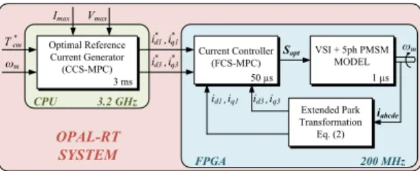
The proposed cascaded MPC technique is implemented in a real-time system (see Fig. 2). The target platform used for this work is the OP5600 real-time simulator complemented with the OP5607 extension module by OPAL-RT. The Xilinx Virtex 7 FPGA of OP5607 is used for both machine simulator and FCS-MPC current controller, and it is running at 200 MHz (frequency of internal clock of the FPGA used for flip-flop triggers). On the other hand, the Intel Xeon CPU of OP5600 is used to communicate with the host PC and to solve the optimal reference generation, sending the obtained results to the FPGA as well as its inputs (such as the reference speed or torque). The CPU performance allows up to 3 ms of sampling time for the optimal reference currents generator for single core mode. Further improvements can be made by parallelizing the solver. In real applications, the switching frequency is limited by the switching losses in the IGBT modules of the VSI. Due to this limitation, the frequency of the FCS-MPC is set to 20 kHz, although the real maximum frequency is higher. This margin can be used to reduce the resource usage in the FPGA by further pipelining the mathematical operations in the predictor of FCS-MPC. The machine simulator is running at 1 MHz with 1 µs of sampling time. Torque, speed, current and voltages signals (the two last ones in dq and phase frames) are available as analog signals from OP5607 and are configured from the host PC. Real-time simulation tests have been carried out in order to validate the proposed approach using the previous described real-time system. Table I summarizes the machine parameters and limitsSopt ωm T * em Vmax Imax Current Controller (FCS-MPC) Extended Park Transformation Eq. (2) iq3 id3, iq1 id1, i* d1i * q1 , i* d3,iq3* CPU 3.2 GHz OPAL-RT SYSTEM 50 µs VSI + 5ph PMSM MODEL 1 µs ωm iabcde FPGA 200 MHz Optimal Reference Current Generator (CCS-MPC) 3 ms
Fig. 2. Proposed cascaded MPC technique.
I. Machine parameters and limits
Parameter Value Resistance R 37 mΩ Inductances Ld1 and Lq1 0.155 mH Inductances Ld3 and Lq3 0.051 mH Flux Φf1 19.4 mWb Flux Φf3 0.675 mWb Pole pairs p 7
Voltage limit Vmax 35 V
Current limit Imax 50 A
Maximum torque Tem,max 19.27 N-m
Base speed ωb 105 rad/s
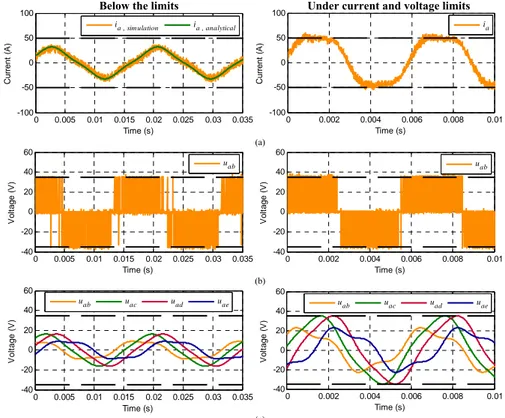
Maximum mechanical speed ωm,max 240 rad/s considered in the tests. Firstly, two different situations have been analysed in Fig. 3 to prove the viability of the cascaded MPC technique: operation below the limits and under current and voltage limits (left and right plots, respectively). In the first (second) case, the machine is maintained at 50 rad/s (150 rad/s), being the reference torque of 10 N-m (20 N-m). Fig. 3a shows the evolution of the current in phase a. In the case of the operation below the limits, the simulation result is compared with the analytical solution, which is easy to obtain imposing the following optimal dq reference currents (from a copper losses point of view) [18]:
0 * = dk i (14) * 3 , 1 2 * em i qi qk qk T i
∑
= = ε ε (15)being εqk the speed-normalized back-EMF. The phase-to-phase voltage uab, obtained from the real-time simulator, is shown in Fig. 3b for both cases. Finally, Fig. 3c depicts all phase-to-phase voltage signals that are filtered offline to be able to see if the voltage limit is reached.
The second test provides the maximum torque versus speed characteristic (see Fig. 4a), with the aim of validating the ability of the cascaded MPC technique to respect the limits over the entire speed range. A speed ramp is imposed to the machine from 0 rad/s (at t=0 s) to the limit speed of 240 rad/s (at t=2 s). The reference torque is set to is maximum value (19.27 N-m), therefore the peak value of phase currents is equal to the limit (50 A) during the whole test. On the other hand, peak values of
phase-to-0 0.005 0.01 0.015 0.02 0.025 0.03 0.035 -40 -20 0 20 40 60 Time (s) V o lt a g e ( V ) uab 0 0.002 0.004 0.006 0.008 0.01 -40 -20 0 20 40 60 Time (s) V o lt a g e ( V ) uab 0 0.005 0.01 0.015 0.02 0.025 0.03 0.035 -100 -50 0 50 100 Time (s) C u rr e n t (A )
ia , sim ulation ia , analytical
0 0.005 0.01 0.015 0.02 0.025 0.03 0.035 -40 -20 0 20 40 60 Time (s) V o lt a g e ( V ) uab uac uad uae 4 6 8 10 12 14 -40 -20 0 20 40 60 V o lt a g e ( V ) uab uac uad uae 0 0.002 0.004 0.006 0.008 0.01 -40 Time (s) (a)
Below the limits
(b)
(c)
Under current and voltage limits
0 0.002 0.004 0.006 0.008 0.01 -100 -50 0 50 100 Time (s) C u rr e n t (A ) ia
Fig. 3. Real-time simulation of an operation below limits (left plots) and under current and voltage limits (right plots). (a) Current in phase a. (b) Phase-to-phase voltage uab. (c) Filtered phase-to-phase voltages.
0 50 100 150 200 250 -5 0 5 10 15 20 25 Speed (rad/s) T o rq u e ( N ·m ) 0 50 100 150 200 250 -100 0 100 200 Speed (rad/s) C u rr e n t (A ) id1 iq1 id3 iq3
Fig. 4. Real-time simualtion of a speed ramp test. (a) Torque-speed characteristic. (b) Evolution in dq1 and
dq3 currents.
phase voltages are always lower or equal to the maximum imposed voltage (35 V). The evolution of dq1 and dq3 currents is plotted in Fig. 4b, showing different behaviours depending on the operating mode. Before the base speed (100 rad/s), the voltage limit is not reached, being id1 and id3 equal to zero (the machine is not flux-weakened). Furthermore, iq1 is positive in order to produce a positive torque with the fundamental of the flux, while iq3 (associated with the third harmonic of the current) is negative to get the maximum peak value for the phase currents, at the price of a negative generated
torque. Once the base speed is reached, id1 and id3 currents become negative (flux-weakening mode) in order to comply with the voltage limit. It is important to note that, from a certain speed, id3 and
iq3 currents are varied (from negative to positive values) in order to maximize the torque produced by the fundamental of the flux while respecting the current and voltage limits.
This analysis proves the optimality of the proposed method, which is only possible because amplitudes and phase shifts of the third harmonics of current and voltage have been optimized in real-time for each operating point, without any simplifications or assumptions as made in other research works present in the literature.
5.
CONCLUSİON
This paper introduces a novel cascaded MPC technique to generate online optimal reference currents in order to get the maximum torque of a multiphase machine while controlling the drive under current and voltage constrains. It is particularly shown how it is important to simultaneously control amplitudes and shifts of current and voltage harmonics to have an optimal solution. More operating modes than for three-phase drives have to be considered, leading to a difficult problem to be analytically solved. The implementation of the technique in a real-time system like OPAL-RT is proposed to numerically solve the problem. Some real-time simulation tests have been carried out to validate the effectiveness of
the proposal. More results will be added in the final version of the manuscript, such as the analysis of the dynamics in the reference currents generation.
ACKNOWLEDGEMENTS
The authors would like to acknowlege the doctoral school of ENSAM and the “Ministerio de Economía y Competitividad” of the Spanish Government under reference DPI2016-76144-R for the financial support of this work.
REFERENCES
[1] E. Levi, “Advances in Converter Control and Innovative Exploitation of Additional Degrees of Freedom for Multiphase Machines,” IEEE Trans. Ind. Electron., vol. 63, no. 1, pp. 433-445, Jan. 2016
[2] X. Xu and D.W. Novotny, “Selection of the flux reference for induction machine drives in the field weakening region,” IEEE Trans. Ind. Appl., vol. 28, no. 6, pp. 1353-1358, Nov./Dec. 1992.
[3] L. Harnefors, K. Pietilainen and L. Gertmar, “Torque-maximizing field-weakening control: design, analysis, and parameter selection,” IEEE Trans. Ind. Electron., vol. 48, no. 1, pp. 161-168, Feb. 2001.
[4] J.M. Kim and S.K. Sul, “Speed control of interior permanent magnet synchronous motor drive for the flux weakening operation,” IEEE Trans. Ind. Appl., vol. 33, no. 1, pp. 43-48, Jan./Feb. 1997.
[5] L. Parsa and H.A. Toliyat, “Five-phase permanent-magnet motor drives,” IEEE Trans. Ind. Appl., vol. 41, no. 1, pp. 30-37, Jan./Feb. 2005.
[6] J. Wang, R. Qu and L. Zhou, “Dual-Rotor Multiphase Permanent Magnet Machine With Harmonic Injection to Enhance Torque Density,” IEEE Trans. Appl. Supercond., vol. 22, no. 3, pp. 5202204-5202204, June 2012. [7] H. Xu, H.A. Toliyat and L.J.Petersen,
“Five-Phase Induction Motor Drives with DSP-Based Control System,” IEEE Trans. Power Electron., vol. 17, no. 4, pp. 524-533, Jul. 2002.
[8] E. Levi, D. Dujic, M. Jones and G. Grandi, “Analytical Determination of DC-Bus Utilization Limits in Multiphase VSI Supplied AC Drives,” IEEE Trans. Energy Convers., vol. 23, no. 2, pp. 433-443, June 2008.
[9] M. Mengoni, L. Zarri, A. Tani, L. Parsa, G. Serra and D. Casadei, “High-Torque-Density Control of Multiphase Induction Motor Drives Operating Over a Wide Speed Range,” IEEE
Trans. Ind. Electron., vol. 62, no. 2, pp. 814-825, Feb. 2015.
[10]L. Lu et al., “Computation of optimal current references for flux-weakening of multi-phase synchronous machines,” IECON 2012 - 38th Annual Conference on IEEE Industrial Electronics Society, Montreal, 2012, pp. 3610-3615.
[11]O. Fall, N.K. Nguyen, J.F. Charpentier, P. Letellier, E. Semail and X. Kestelyn, “Variable speed control of a 5-phase permanent magnet synchronous generator including voltage and current limits in healthy and open-circuited modes”, Electric Power Systems Research, vol. 140, pp. 507-516, Nov. 2016.
[12]P. Cortes, M.P. Kazmierkowski, R.M. Kennel, D.E. Quevedo and J. Rodriguez, “Predictive Control in Power Electronics and Drives,” IEEE Trans. Ind. Electron., vol. 55, no. 12, pp. 4312-4324, 2008.
[13]M. R. Arahal, F. Barrero, S. Toral, M. J. Duran and R. Gregor, “Multiphase current control using finite-state model-predictive control,” Control Eng. Pract., vol. 17, no. 5, pp. 579–587, May 2009.
[14]J. Rodriguez, M.P. Kazmierkowski, J.R. Espinoza, P. Zanchetta, H. Abu-Rub, H.A. Young and C.A. Rojas, “State of the Art of Finite Control Set Model Predictive Control in Power Electronics,” IEEE Trans. Ind. Informat., vol. 9, no. 2, pp. 1003-1016, May 2013.
[15]X. Kestelyn, O. Gomozov, J. Buire, F. Colas, N.K. Nguyen and E. Semail, “Investigation on model predictive control of a five-phase permanent magnet synchronous machine under voltage and current limits,” IEEE International Conference on Industrial Technology (ICIT), Seville, 2015, pp. 2281-2287.
[16]X. Kestelyn, E. Semail and J.P. Hautier, “Vectorial multi-machine modeling for a five-phase machine,” Proc. Int. Conf. Electrical Machines (ICEM), Bruges, 2002, CD-ROM, Paper 394.
[17]O. Gomozov, J.P. Trovao, X. Kestelyn and M. Dubois, “Adaptive Energy Management System Based on a Real-Time Model Predictive Control with Non-Uniform Sampling Time for Multiple Energy Storage Electric Vehicle,” IEEE Trans.
Veh. Technol., DOI:
10.1109/TVT.2016.2638912.
[18]X. Kestelyn and E. Semail, “A Vectorial Approach for Generation of Optimal Current References for Multiphase Permanent-Magnet Synchronous Machines in Real Time,” IEEE Trans. Ind. Electron., vol. 58, no. 11, pp. 5057-5065, Nov. 2011.