Any correspondence concerning this service should be sent to the repository administrator:
[email protected]
To link to this article
: DOI:10.1016/j.matchemphys.2012.09.049
http://dx.doi.org/10.1016/j.matchemphys.2012.09.049
This is an author-deposited version published in:
http://oatao.univ-toulouse.fr/
Eprints ID: 8491
To cite this version:
Alexis, Joël and Gaussens, Clélia and Etcheverry, Bernard and Bonino,
Jean-Pierre Development of nickel phosphorus coatings containing micro particles of
talc phyllosilicates. (2013) Materials Chemistry and Physics (n° 137 ). pp.
723-733. ISSN 0254-0584
O
pen
A
rchive
T
oulouse
A
rchive
O
uverte (
OATAO
)
OATAO is an open access repository that collects the work of Toulouse researchers and
makes it freely available over the web where possible.
Development of nickelephosphorus coatings containing micro particles of talc
phyllosilicates
Joël Alexis
a,*, Clélia Gaussens
a, Bernard Etcheverry
b, Jean-Pierre Bonino
caUniversité de Toulouse, INPT-ENIT, Laboratoire Génie de Production, Ecole Nationale d’Ingénieurs de Tarbes, 47 avenue d’Azereix, BP 1629, 65016 Tarbes cedex, France bALSTOM TRANSPORT, BP4, Rue du Docteur Guinier, 65601 SEMEAC cedex, France
cCIRIMAT-CNRS (UMR n5085), Université Paul Sabatier, 118 route de Narbonne, 31062 Toulouse cedex 4, France
h i g h l i g h t s
<Nickel phosphorus composite coatings NiP-talc particles are developed.
<The content of particles increase with talc content of the bath and are distributed randomly on the coatings. <A significant decrease in rigidity is observed by adding small amounts of particles of talc.
<The toughness increases with the insertion of talc when the deposit is heat treated at 420 C <Rough or heat treated at 600 C deposits have a ductile behavior unlike the treated at 420 C deposits.
Keywords: Mechanical properties Coatings Adhesion Composite materials Hardness
a b s t r a c t
The present work aims to characterized nickel phosphorus coatings co-deposited with talc particles on steel. The NiP-talc composite deposits were developed to serve as hard coatings with a lubricating effect at 600 C. This process, which is free of hexavalent chromium, could provide a reliable substitute for the electrodeposition of hard chromium coating used in industrial applications. Local responses to static and dynamic mechanical loading have been obtained by and microhardness, microtensile and nano-scratch testing. The hardness and stiffness values slightly decrease when the amount of talc increases for untreated coatings. In contrast, a 420 C heat treatment leads to high hardness and Young’s modulus values due to crystallization. Moreover, a 600 C heat treatment lowers these values through overageing. A 420 C heat treatment greatly improves the adherence and the cohesion of the coatings containing talc.
1. Introduction
Nickel electroless plating is an autocatalytic deposition process in which nickel ions in aqueous solution are reduced at the catalytic surface of the substrate by a reducing agent that has also been added to the solution. The reducing agents used are phosphorus salts, such as NaPH2O2 [1], and the coatings obtained on the substrate are
metallic solid solutions of nickel and phosphorus. By comparison with electroplating, electroless deposition offers the advantage of obtaining a quite uniform thickness, regardless of the roughness of the substrates. After heat treatments of the NiP solid solutions
involving the precipitation of nickel phosphides in a nickel matrix
[2], an increase in hardness and wear resistance is induced; this behavior is one of the major reasons for the widespread use of electroless NiP coatings. Composite coatings containing hard or lubricating particles have also received attention for tribological applications[3]. In this case, the process consists of incorporating particles into the NiP matrix from an electrolyte containing particles in suspension. The particles adsorbed on the substrate during the growth of the matrix are definitely incorporated into the coating.
The insertion of particles in the NiP matrix is intended to increase the hardness and wear resistance, to reduce friction or to increase the resistance to corrosion. Their nature and shape differ depending on the goals. The reinforcement of the second phase can be hard oxides (Al2O3and TiO2)[4]or carbide particles (SiC[3], WC
[5], B4C[6], diamond[7]and nitride[8]). Solid lubricants (PE[9],
PTFE [10], graphite [11] and MoS2 [12]) can reduce the friction
coefficient. Nanoparticles (SiO2, CeO2[13], Zn3(PO4)2, ZnSnO3and
* Corresponding author. Tel.: þ33 0 562442723; fax: þ33 0 562442708. E-mail addresses: [email protected] (J. Alexis), [email protected] (C. Gaussens), [email protected] (B. Etcheverry), [email protected](J.-P. Bonino).
ZnSiO3[14]) have been deposited to improve the corrosion
resis-tance. Some electroless nickel co-deposits, such as Ni-PTFE, have been developed by the industry because of their significant resis-tance to corrosion and wear, but most co-deposits are still at the experimental stage [8,15e18]. The aim of this study was to obtain amorphous electroless nickelephosphorus (NiP) coatings containing talc micro-particles (formula: Mg3Si4O10(OH)2) and
to investigate both the coating structure and its mechanical prop-erties. The effect of the talc particle content on hardness and adherence was particularly analyzed, before and after various 1-h heat treatments. The influence of the phosphorus rate is cited but is not the subject of this study because it is well known[19e21]. The deposits are developed for tribological high-temperature applica-tions to replace hard chromium. Talc was chosen because it is resistant until 900 C. The goal is to develop a hard (1000 HV) and lubricating coating [22]. Indeed, the first tribological tests have shown the beneficial role of talc on the reduction of the friction coefficient for heat-treated deposits[23].
2. Experimental procedure 2.1. Coatings and sample preparation
The composite electroless NiP-talc coatings were deposited on low-alloy steel substrates (36NiCrMo16). The substrates were heat-treated to obtain a hardness of 450 HV10. The samples were
polished and pretreated in an alkaline bath (pH ¼ 10) and acetone
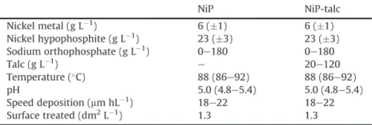
and then pickled in a diluted hydrofluoric acid bath with inter-mediate water rinses. The samples are either round sheets with a 1.7 cm2surface area or standardized microtensile samples. The bath composition (Europlate Ni216 commercial bath) and opera-tion condiopera-tions used for preparing the NiP-talc composite coatings are given inTable 1. This bath was chosen because it yielded the optimal hardness. The bath was stirred by a rotating stirring rod (to keep particles from settling) with a rate of 500 rev min"1. The talc
particles employed were pretreated with carboxyl methyl cellulose
(CMC) (long-chain polysaccharide), a well-known polymer
depressant, to reduce the floatability of talc[24]. Talc is a 2:1 layer clay (phyllosilicate family) that links two tetrahedral sheets with one octahedral sheet. The average diameter when diluted in osmosed water was measured by photon correlation spectroscopy (Zetasizer 4, Malvern Instrument
) at 1.3
m
m, and the talc particle concentrations in the bath varied from 20 to 120 g L"1talc. Thedeposition process was carried out for 2 h at a constant tempera-ture of 88 C with a fixed pH of 5 with or without talc particles. The electroless composite NiP-talc layers and the NiP layers were deposited to a thickness of approximately 30e40
m
m. The number of incorporated particles by unit area was evaluated by image analysis (with Imagetools software) of micrographs obtained by Scanning Electron Microscopy (SEM). InFig. 1, an increase in the number of particles incorporated into coatings with an increase in the talc content of the bath can be observed, while the phosphorus contained in the NiP matrix simultaneously increased slightly from 4.69 to 5.65 wt. % for 120 g L"1 of talc in the bath. Indeed, forother electroless and electroplating composite coatings, such as NiPeSi3N4, CeO2, or TiO2, it has been shown by Balaraju[25]that an
effective factor for trapping particles in the coating matrix is the particle content of the bath. The samples were heat-treated for 1 h at 420 C or 600 C under a controlled atmosphere and then were allowed to cool down in a high-vacuum environment for at least 20 min prior to their exposure to the atmosphere.
2.2. Observations and measurements
The surface morphology of both NiP and NiP-talc layers was examined by means of scanning electron microscopy (Philips SEM
Table 1
Composition and deposition parameters of the electroless NiP (Europlate Ni216) commercial bath used.
NiP NiP-talc
Nickel metal (g L"1) 6 (#1) 6 (#1)
Nickel hypophosphite (g L"1) 23 (#3) 23 (#3)
Sodium orthophosphate (g L"1) 0e180 0e180
Talc (g L"1)
e 20e120
Temperature (C) 88 (86e92) 88 (86e92)
pH 5.0 (4.8e5.4) 5.0 (4.8e5.4)
Speed deposition (mm hL"1) 18e22 18e22
Surface treated (dm2L"1) 1.3 1.3
515
) equipped with an electron dispersive spectrometer that was used for the determination of the chemical composition of the deposits. An X-ray diffraction analysis has also been performed using a Cu Ka X-ray source (Philips X’Pert MRD) to study the
coatings’ structure changes and the residual stresses. A VYCO NT1100 optical profiler (Veeco
) was employed to provide rough-ness data. Five replicate scans were performed on different zones. The average roughness parameter (Sa) and the Surface Area Ratio (Sdr) were measured. The Surface Area Ratio, Sdr, is the ratio between the surface area (taking the z height into account) and the area of the flat x-y plane. This parameter, also called the Developed Interfacial Area Ratio, is expressed as the percentage of additional surface area contributed by the texture compared with an ideal plane the size of the measurement region. Nanohardness tests were
performed with the MTS XP
nanoindenter in dynamic mode, making it possible to obtain the Hardness and Young’s Modulus values of the coatings. The indenter used is a Berkovitch pyramidal indenter. Nanoindentation tests were also performed on deposits treated at 600 C to determine the influence of over-aging. For this study, two types of adhesion tests were used, the well-known and common microscratch test and a microtensile test. The
micro-scratch tests were realized with a CSM
microscratch tester equipped with a diamond Rockwell indenter with a 200
m
m radius. The technique involves generating a controlled scratch with a dia-mond tip on the sample under test. The tip, either made of diadia-mond or sharp metal, is drawn across the coated surface under a progressive load. At a certain critical load, the coating will start to fail. The critical loads are very precisely detected by means of an acoustic sensor connected to the load arm together with observa-tions from a built-in optical microscope. The critical load data are used to quantify the adhesive properties of different filmesubstrate combinations. Three scratches are made on each coating with the following parameters: initial load: 0.1 N; final load: 20 or 30 N;scratch length: 2 mm; scratch speed: 1 mm min!1; acoustic
emission threshold: 9; space between two scratches: 2 mm. Physicoechemical analyses by X-ray energy spectrometry are made to determine the type of rupture (adhesive or cohesive).
The microtensile test is used on systems made up of a ductile, coated substrate to analyze the mechanical stability and the damage to the deposits[26,27]. These tests require various experimental measurements, such as the tensile strength and spacing inter-crack characteristic of film split up. During the tensile tests, a low rate of
deformation equal to 0.06 mm min!1 has been implemented.
According to the Agrawal and Raj model[28], the maximum inter-facial shearing force,
s
, developed for the interface between thedeposit and the metal, is related to the tensile strength of the coating,
s
, by equation(1), wheres
¼E3f, with 3frepresenting thestress corresponding to the beginning of cracking of the deposit. E and
d
are, respectively, the Young modulus and the thickness of the coating. Finally,l
is the wavelength of the sine function that definesthe maximum interfacial shearing force. It is equivalent to a virtual spacing inter-crack characteristic of saturation in transverse cracks, in spite of the increase in the tensile stress. This equation is valid for a system film/coating free from residual stresses. This model was then modified to extend its validity for a thicker and harder deposit with residual stresses
s
r(equations(2) and (3))[29].s
¼pds
fl
; (1)s
e ¼s
fþs
r; (2)s
¼pds
el
; (3)3. Results and discussion 3.1. Morphology & topography
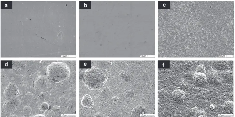
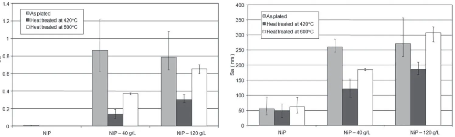
The SEM micrographs of representative NiP and NiP-talc deposits are presented inFig. 2. The presence of talc particles in the NiP layer induced modifications of the surface morphology and an increase in the roughness of the deposits (Fig. 3). The nodule quantity increased with the presence of talc in the coatings. Moreover, it would seem
Fig. 2. Surface morphology of (a) as-plated NiP, (b) NiP heat-treated at 420 C, (c) NiP heat-treated at 600 C, (d) as-Plated NiP-120 g L!1talc, (e) NiP-120 g L!1talc heat-treated at
that the insertion of talc particles is responsible for the lower cohesion of the coatings. Indeed, micro-porosities are present at the surface of the deposits containing talc particles. The surface exam-ination after heat treatments shows that the deposits become slightly smoother (Fig. 3). The heat treatments have a slight effect on the morphology (Fig. 2); only the 600 C heat treatment tends to increase the sub-micron pores observed on the untreated deposits. 3.2. Microstructure
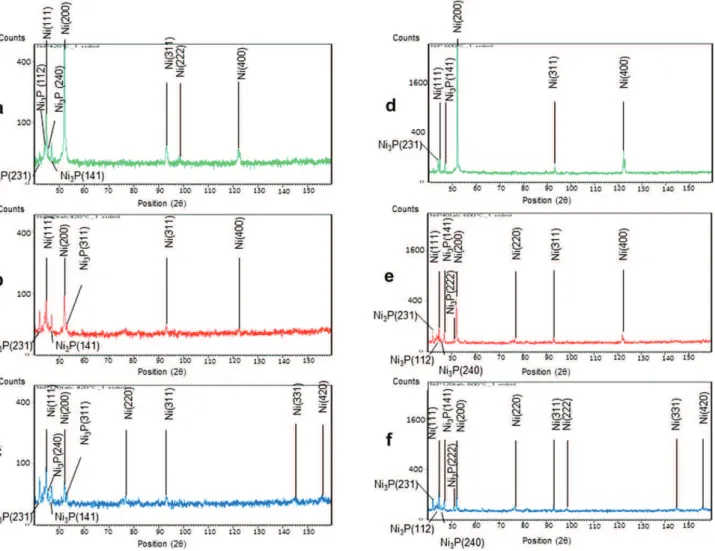
The diffractograms of the various deposits according to their content of talc particles are shown inFig. 4. These measures show that whatever the content of talc, the deposits are poorly crystalline
due to their phosphorus content (z5 wt. %) (Table 2). With the increase of the talc content of the bath, a slight modification of the expansion or location of the diffraction peaks is observed. The plane (200) gradually disappears. The intensity of the peak (111) is larger for rough deposits without talc particles, and the peak width at half height is less important; this is a sign of greater crystallinity. Therefore, the particles of talc appear to play a role in the crystal-linity of the coatings. Indeed, the addition of talc in coatings is accompanied by a very slight increase of phosphorus in coatings that become increasingly amorphous.
It has been confirmed by several studies that structural changes from an amorphous state to a crystalline state can be obtained in NiP electroless coatings over 300 C[30,31]. Controlled atmosphere heat treatments (420 Ce1 h and 600 Ce1 h) of both NiP-talc and NiP lead to rapid crystallization of the amorphous matrix. Based on the DSC and TEM analysis, many authors have shown that the thermal stability of low-phosphorus coatings seems superior to that of high-phosphorus coatings, but the formation of Ni3P and the
crystallization is completed at 450 C[32e34]. The introduction of talc in the coating does not alter the nature of the phases present but seems to have an effect on texture (Fig. 5). It has been observed in these composite deposits that there are no other phases except Ni and Ni3P. The intensity ratio between the diffraction peaks varies
with the insertion of talc particles. Similar structural changes have been reported for NiPeSiC electroless composite coatings[35]. 3.3. Mechanical properties
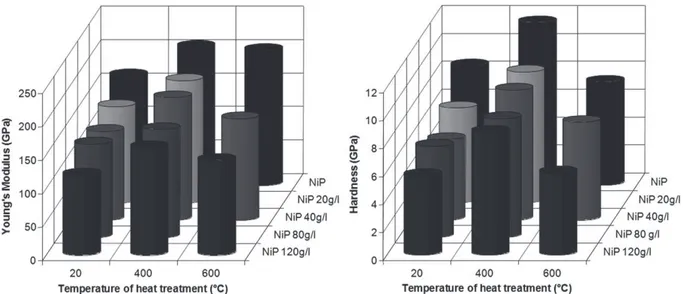
Nanoindentation tests are performed to determine the hardness and the rigidity of the coatings. The loading-unloading curves (Fig. 6) do not vary significantly according to the talc content. Only the load reached for an imposed displacement of 2000 nm decrease with the insertion of talc. The springback of approximately 450 nm is the same regardless of the amount of talc coating present. A significant decrease in rigidity is observed by adding small numbers of particles (Fig. 7). Beyond 20 g L!1of talc in the bath, the rigidity continues to decline to E ¼ 120 GPa for the NiP-120 g L!1talc. A similar trend was observed for hardness, which decreases sharply
Fig. 3. Roughness measurements for the as-plated and heat-treated NiP and NiP-talc composite coatings.
Fig. 4. XRD patterns of as-plated (a) NiP coating, (b) NiP-40 g L!1talc coating and (c)
NiP-120 g L!1talc coating.
Table 2
Deposit composition as a function of the talc content of the bath. Talc content of the bath (g L!1) Coating composition (wt. %)
Ni P Mg Si O
0 95.31 4.69 e e e
40 88.09 5.46 1.28 1.17 4.00
with the insertion of a small quantity of talc (HNiP¼ 8.5 GPa and HNiP-20¼ 6.7 GPa). The hardness then decreases slowly beyond this concentration in the bath (HNiP-Talc120¼ 5.7 GPa). This decrease can be explained only by the incorporation of particles with very low mechanical properties (H and E), such as talc (Fig. 8), and not by the slight increase in the phosphorus content in the matrix. Indeed, some authors [36]have reported that an increase of phosphorus involves a hardening of the NiP solid solution.
The heat treatments have a significant influence on the hardness and rigidity of the coatings. Indeed, the curves of loadinge unloading vary depending on the heat treatment (Fig. 6). The springback is greater after treatment at 420 !C and lowest after
treatment at 600!C. Furthermore, the load reached for an imposed
displacement of 2000 nm increases after treatment at 420!C and
decreases after treatment at 600 !C. Note the large dispersion of
measurements recorded for deposits treated at 600!C. The
varia-tion of Young’s modulus and the hardness as a funcvaria-tion of temperature treatment are presented inFig. 7. As noted earlier, the deposit without talc is noteworthy. However, Young’s modulus and the hardness increase when the rough as-deposited coating is treated at 420!C, irrespective of the talc content. These hardness
curves are typical of a precipitation hardening because the
hard-ness H increases up to a maximum (420 !C-aging) and then
decreases (600!C-overageing). The increase in hardness and
stiff-ness are due to the precipitation of nickel phosphides (Ni3P) and
crystallization of the Ni matrix.
Beyond 420!C and until 600!C, Young’s modulus of the coating
produced without talc fell slightly but remained above that of the rough deposit. The small reduction shows that no significant change in structure occurs between these two temperatures. The same is not true for deposits containing talc. The hardness also decreases between a deposit treated at 420!C and another treated
at 600!C. This sharp decrease in hardness is due to grain growth, to
Fig. 5. XRD patterns of (a) NiP, (b) NiP-40 g L"1talc and (c) NiP-120 g L"1talc coatings heat-treated at 420!C and (d) NiP, (e) NiP-40 g L"1talc and (f) NiP-120 g L"1talc coatings
heat-treated at 600!C.
Fig. 6. Nanoindentation loadedepth (Peh) curves of NiP and NiP-120 g L"1talc
the coalescence of the precipitates and/or to degradation or debonding of mineral fillers.
The toughness of the coatings was determined from Vickers hardness tests. The crack length was measured as a function of the applied load[37,38]. The method of successive surface polishing is used to confirm that the cracking is Palmqvist-type cracking, i.e., the beginning of the crack deviates from the edge of the footprint as clarified by the polishing steps. The Palmqvist-type cracking justifies the choice of the model of Shetye, Wright, Mincer and
Clauer for determining the toughness (equation (4)) [39]. This model was used because it has the advantage of not being a func-tion of Young’s modulus or the hardness of the sample.
Kc ¼ 0:0319 P.!al1=2"
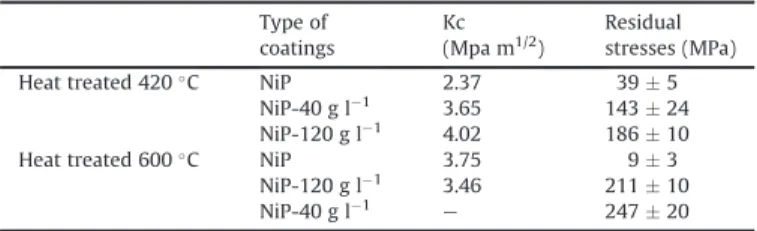
(4) The toughness increases with the insertion of talc when the deposit is heat-treated at 420 !C (Table 3). In addition, heat
Fig. 7. Young’s modulus and hardness of NiP coating and NiP-talc coatings as deposited and treated at various temperatures.
Fig. 8. Evolution of the hardness and Young’s modulus measured on a macro-particle of talc according to the orientation of the layered structure (0!, 45!and 90!with regard to the
treatment at 600 C increases the coating’s toughness. The pres-ence of talc does not affect the toughness of deposits processed at
600 C. A. Roman et al. [40] found comparable values:
K ¼ 1:5 MPa ffiffiffiffiffipmfor the 300 C heat treatment and 2:1 MPa ffiffiffiffiffipmfor the 600 C heat treatment.
The residual stresses in the heat-treated coatings have been determined by X-ray diffraction. Evaluation of the residual stresses by the sin2
j
method was performed. A copper anode X-ray tubewas used, and measurements were made on the (420) nickel diffraction peak at a 2
q
angle of approximately 155.6 with anirradiated area of approximately 4 mm2. Seven
j
offsets were measured for the two principal in-plane stress directions. A Gaussian function was used to fit the diffraction peaks. The parameters are S1 ¼ 1/TPa and S2 ¼ 6.32/TPa. All types of deposits are tested in a slight state of tension (Table 3). Talc tends to increase this state of tension.The curves and optical observations of scratches are presented inFig. 9. The response of the coating and substrate depends on the heat treatment and the amount of talc in the bath. Two mechanical behaviors stand out: ductile behavior for as-deposited coating and deposits heat-treated at 600 C and fragile behavior for deposits treated at 420 C (Fig. 10). The ratio between the thickness of the deposit at the side of the track and at the center is a discriminating parameter for ductile (ratio> 1.4) and brittle behavior (compared to 1). The influence of heat treatment is determined on coatings with 120 g L#1talc; a ratio of 1.61 is obtained for the untreated coating,
a ratio of 1.07 for the heat-treated at 420 C and a ratio of 1.44 for the coating heat-treated at 600 C. These results show that the
untreated and treated coatings at 600 C are more ductile.
The plastic deformation is absorbed mainly by the coating. For the coating treated at 420 C, the coatings’ thickness remains constant, regardless of the zone observed; the plastic deformation is located
Table 3
Toughness and residual stresses of NiP, NiP-40 g L#1and NiP-120 g L#1coatings after
treatment at 420 C and 600 C. Type of coatings Kc (Mpa m1/2) Residual stresses (MPa)
Heat treated 420 C NiP 2.37 39 $ 5
NiP-40 g l#1 3.65 143 $ 24
NiP-120 g l#1 4.02 186 $ 10
Heat treated 600 C NiP 3.75 9 $ 3
NiP-120 g l#1 3.46 211 $ 10
NiP-40 g l#1
e 247 $ 20
Fig. 9. Curves and optical observations of scratches on NiP and NiP-120 g L#1coatings, respectively, as deposited (a, b), after treatment at 420 C (c, d) and after treatment at 600 C
in the substrate rather than in the fragile coating. The deposit only transmits the mechanical stress introduced by the indenter. The influence of the amount of talc is determined from the surfaces treated at 600 C; the values are 1.57, 1.46 and 1.44 for 0, 40 and
120 g L!1of talc, respectively. These values decrease slightly when
the amount of talc is increased. To determine the critical loads, the parameters used were the acoustic emission, depth and residual optical observations. All critical loads are determined depending on
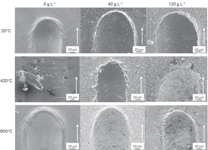
Fig. 10. SEM observations of the scratches on NiP, NiP-40 g L!1talc and NiP-120 g L!1talc coatings as deposited, after treatment at 420 C and after treatment at 600 C.
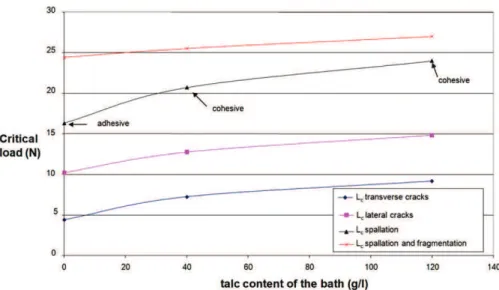
Fig. 12. Critical loads as a function of the talc content in the bath (g L 1) for coatings heat-treated at 420!C.
Fig. 13. Graphic representation showing the various scratch test failure modes that dominate as a function of the coating and the substrate hardness of the coatings (Hc and Hs, respectively) for the different NiP and NiP-talc coatings.
the type of coating: talc content and heat treatment. Moreover, scanning electron microscopy observations were performed to attribute physical phenomena to each critical load (Lc): simple cracking (LC1&2: lateral or transverse), multiple cracking (LC3:
fragmentation) and spalling (LC4&5: adhesive or cohesive). The
results are summarized in Fig. 11. For coatings heat-treated at 420 C, the talc particles delay the onset of phenomena such as spalling (Fig. 12). This behavior is due to a better mechanical accommodation. For coatings heat-treated at 600 C, talc seems to provide some stress accommodation, and plastic deformation is slightly less important. These behaviors are consistent with the fracture map patterns describing the hardness of the coating and the substrate provided by Bull (Fig. 13)[41].
From the tensile tests (Fig. 14), the crack density due to the strain rate was measured during the test by video acquisition. Talc seems to modify the adherence of the coatings. It was shown that the rate of cracking to saturation increases with the talc content for untreated coatings. Moreover, the cracks are deviated on coatings containing talc. The observations by SEM of the rupture surface confirm this result and attest to the brittle fracturing of the coat-ings. The rupture is adhesive for untreated deposits without talc and becomes mixed with the insertion of talc. The cohesion of the particles/matrix seems less strong than that of the deposit/ substrate. The crack density due to the rate of deformation increases significantly after a heat treatment. The observations made in situ by an optical microscope and made post mortem by SEM confirm the increase in the adherence of the heat-treated deposits. The coatings remain adherent close to the rupture zone of the substrate (Fig. 14). The influence of talc on the deviation of the cracks is less obvious because of the better cohesion of the particles/matrix but more importantly because of the improved rigidity of the deposits. The ruptures of coatings are adhesive without talc and are cohesive with talc. The interfacial shear stress was thus given by the model of Agrawal and Raj without taking into account the residual stresses (
s
AeR ands
res) of the coatings(Table 4). Note that for the studied coatings,
s
AeRands
residualarealmost identical because the values of
s
residual(a few hundreds of MPa) are negligible compared withs
applied(on the order of GPa). The heat treatment increases the adherence of the deposit considerably. It also seems that the talc addition improves the behavior of the coating. These results confirm preceding experi-mental results and testify to the relevance of using the model to quantitatively investigate the adherence of the studied coatings.4. Conclusion
The present investigation has demonstrated that talc powder could be incorporated successfully in a NieP. The observations
carried out with optical microscopy showed good homogeneity of the deposits. The roughness of the deposits increases with the incorporation of talc particles in the bath due to an important morphological change observed by scanning electron microscopy. In fact, the NiP structure changes radically to a globular structure with the addition of dispersoids in the solution. The heat treat-ments do not significantly influence the roughness but do modify the microstructure. This study highlights several interesting mechanical properties of the composite NiP coatings with talc dispersoids. The values of the hardness and Young’s modulus decrease slightly with the increase in talc content when the coating was not treated thermally. In contrast, with a recrystallization heat
treatment at 420 C, the hardness and Young’s modulus remain
quasi-constant, regardless of the content of dispersoids (20e 120 g L!1 in solution). This treatment produces desirable
hard-ness and Young’s modulus values (from 8 to 11 GPa for nano-hardness and Young’s modulus values from 160 to 210 GPa as a function of the talc content) due to the Ni3P precipitation. Finally,
a 600 C treatment degrades these parameters considerably. The hardness increases with the insertion of talc when the deposit is heat-treated at 420 C or with a heat treatment at 600 C. Two separate mechanical behaviors are shown by a scratch test as a function of the intrinsic properties of the coatings: ductile behavior for rough deposits and those heat-treated at 600 C and fragile behavior for deposits treated at 420 C (Fig. 10). The
microtensile tests showed that a 420 C treatment causes an
important improvement in the adhesion level of the coating, more precisely, of the matrix NiP. The talc content also increases the adhesion of the untreated or heat-treated coatings. The rupture is cohesive when the coatings contain talc dispersoids.
Acknowledgments
This study received the financial support of the “Conseil Régional de Midi Pyrénées” under the project heading “multipur-pose composite Coatings for the industry of transport”.
References
[1] T.S.N. Sankara Narayanan, S. Selvakumar, A. Stepen, Surface and Coatings Technology 172 (2) (2003) 298e307.
[2] A. Brenner, P. Couch, E. Williams. Research paper n2061, Journal Research National Bureau of Standards 44 (1) (1950) 109e122.
[3] I.R. Aslanyan, J.P. Bonino, J.P. Celis, Surface and Coatings Technology 200 (2006) 2909e2916.
[4] J.N. Balaraju, Kalavati, K.S. Rajam, Surface and Coatings Technology 200 (12e 13) (2006) 3933e3941.
[5] A. Zoildis-Karathanasis, E.A. Pavlatou, N. Spyrellis, Electrochimica Acta 54 (2009) 2563e2570.
[6] S.M.M. Vaghefi, A. Saatchi, M. Ebrahimian-Hoseinabadi, Surface and Coatings Technology 168 (2003) 259e262.
Table 4
Critical stresses (sAeR) determined by the model of Agrawal and Raj for each type of coating.
Treatments Coatings ef(mm) l0(mm) Ef(Gpa) 3 f(%) sR(GPa) sAeR(GPa) srés(GPa) Rupture mode
Untreated NiP 35.4 1562 164 1.37 e 0.08 e Adhesive
NiP-20 g l!1 38.6 200 140 3.75 e 0.28 e Mixed NiP-40 g l!1 35.4 451 134 1.94 e 0.32 e Mixed NiP-80 g l!1 39.3 100 130 3.51 e 3.03 e Cohesive NiP-120 g l!1 47.8 44 119 4.34 e 9.96 e Cohesive
Heat treated at 420 C NiP 34.3 27 201 0.4 0.039 1.1 1.14 Cohesive
NiP-20 g l!1 37.5 10 180 1.67 e 3.89 e Cohesive NiP-40 g l!1 36.8 31 181 2.06 0.143 4.45 4.59 Cohesive NiP-80 g l!1 39.4 15 160 1.24 e 2.45 e Cohesive NiP-120 g l!1 47.7 34 172 2 0.186 6.35 6.54 Cohesive
Heat treated at 600 C NiP 36.8 148 202 1.54 0.009 1.21 1.22 Adhesive
NiP-40 g l!1 42.2 299 152 2 0.211 0.8 1.01 Adhesive
[7] V.V.N. Reddy, B. Ramamoorthy, P.K. Nair, Wear 239 (2000) 111e116. [8] O.A. Leon, M.H. Staia, H.E. Hintermann, Surface and Coatings Technology 108
(1998) 461e465.
[9] Z. Abdel Hamid, I.M. Ghayad, Materials Letters 53 (2002) 238e243. [10] M.D. Ger, B.J. Hwang, Materials Chemistry and Physics 76 (2002) 38e45. [11] Y.T. Wu, L. Lei, B. Shen, W.B. Hu, Surface and Coatings Technology 201 (2006)
441e445.
[12] G. Straffelini, D. Colombo, A. Molinari, Wear 236 (1e2) (1999) 179e188. [13] R. Xu, J. Wang, Z. Guo, H. Wang, Journal of Rare Earths 26 (4) (2008)
579e583.
[14] M.H. Ma, J.X. Chen, X.H. Li, Journal of Inorganic Chemistry 17 (1) (2001) 101e107.
[15] Q. Zhao, Y. Liu, H. Muller-Steinhagen, G. Liu, Surface and Coatings Technology 155 (2002) 279e284.
[16] E. Pena-Munoz, P. Berçot, A. Grosjean, M. Rezrazi, J. Pagetti, Surface and Coatings Technology 107 (1998) 85e93.
[17] P. Berçot, E. Pena-Munoz, J. Pagetti, Surface and Coatings Technology 157 (2002) 282e283.
[18] Y.S. Huang, X.T. Zeng, I. Annergren, F.M. Liu, Surface and Coatings Technology 167 (2003) 207e211.
[19] D.B. Lewis, G.W. Marshall, Surface and Coatings Technology 78 (1996) 150e156.
[20] C.C. Hu, A. Bai, Materials Chemistry and Physics 77 (2003) 215e225. [21] M.H. Seo, J.S. Kim, W.S. Hwang, D.J. Kim, S.S. Hwang, B. Sun Chun, Surface and
Coatings Technology 176 (2004) 135e140.
[22] B. Etcheverry, PhD thesis, Institut National Polytechnique de Toulouse, 2006. [23] B. Etcheverry, F. Le Coz, J. Alexis, J.Y. Paris, J.A. Petit, Proceeding of the 18th International Conference on Surface Modification Technologies, 2006, 355e363.
[24] P. Bacchin, J.-P. Bonino, F. Martin, M. Combacau, P. Barthes, S. Petit, J. Ferret, Colloids and Surfaces A Physicochemical and Engineering Aspects 272 (2006) 211e219.
[25] J.N. Balaraju, PhD thesis, IIT Madras, Chennai, 2000.
[26] A. Mezin, J. Lepage, N. Pacia, D. Paulmier, Thin Solid Films 172 (2) (1989) 197e209. [27] P.H. Wojciechowski, M.S. Mendiola, Journal of Vacuum Science Technology A7
(3) (1989) 1282e1287.
[28] D.C. Agrawal, R. Raj, Acta Metallurgica 37 (1989) 1265e1270.
[29] B.F. Chen, J. Hwang, I.F. Chen, G.P. Yu, J.H. Huang, Surface and Coatings Technology 126 (2000) 91e95.
[30] S. Vaillant, PhD thesis, Institut National Polytechnique de Toulouse, 2002. [31] G. Jiaqiang, W. Yating, L. Lei, S. Bin, H. Wenbin, Materials Letters 59 (2005)
1665e1669.
[32] I. Apachitei, F.D. Tichelaar, J. Duszczyk, L. Katgerman, Surface and Coatings Technology 149 (2002) 263e278.
[33] Th. Hentschel, D. Isheim, R. Kirchheim, F. Muller, H. Kreye, Acta Materialia 48 (2000) 933e941.
[34] B. Farber, E. Cadel, A. Menand, G. Schmitz, R. Kirchheim, Acta Materialia 48 (2000) 789e796.
[35] J. Alexis, B. Etcheverry, J.D. Beguin, J.-P. Bonino, Materials Chemistry and Physics 120 (2010) 244e250.
[36] C.C. Hu, A. Bai, Materials Chemistry and Physics 77 (2002) 215e225. [37] C.B. Ponton, R.D. Rawlings, Materials Science Technology 5 (1989) 865e872. [38] C.B. Ponton, R.D. Rawlings, Materials Science Technology 5 (1989) 961e976. [39] D.K. Shetty, I.G. Wright, P.N. Mincer, A.H. Clauer, Journal of Material Science 20
(1985) 1873e1882.
[40] A. Roman, D. Chicot, J. Lesage, Surface and Coatings Technology 155 (2002) 161e168.