Journal of Fundamental and Applied Sciences is licensed under aCreative Commons Attribution-NonCommercial 4.0 International License.Libraries Resource Directory. We are listed underResearch Associationscategory.
THE INFLUENCE OF CO2+CONCENTRATION ON THE ELECTRODEPOSITION OF ZNNI FILMS TO OBTAIN THE ZNNI–CO COMPOSITE COATINGS
M. Diafi1*, K. Degheche2, H. Ben Temam1
1
Physic Laboratory of Thin Films and Applications, University of Biskra, 07000, Algeria 2
Departement of chemical industry, University of Biskra, 07000, Algeria
Received: 28 Octobre 2016 / Accepted: 17 December 2016 / Published online: 01 January 2017
ABSTRACT
In this work we have done an experimental study of Zinc- Nickel composite coatings. For this, the influence of the cobalt concentration was the principal object in order to improve the resistance of the corrosion of the coatings, which has been made by electroplating on steel substrates previously treated, have been studied by several characterization methods, as the X-ray diffraction, micro-hardness measurement and scanning electron microscopy (SEM), protection against corrosion properties studied by potentiodynamic polarization measurements (Tafel) and electrochemical impedance spectroscopy (EIS) to the potential of corrosion free . The parameters wich characterize the corrosion behavior; can be determined from the Nyquist plots. It has been observed that the ternary Zn–Ni–Co alloy is characterized by enhanced the resistance of corrosion compared to the binary Zn–Ni alloys. and the addition of Co in the Zn-Ni increases the micro-hardness, XRD and SEM results and identify any coatings Zn-Ni-Co alloy composition reveals that γ-Ni5Zn21 phase, Co matrix phase and pure zinc phase.
Keywords: Alloy, Nickel, Zinc, Microhardness, Electrodeposition, Corrosion resistance.
Author Correspondence, e-mail:diafimalika@gmail.com doi:http://dx.doi.org/10.4314/jfas.v9i1.7
1. INTRODUCTION
The use of coating as anticorrosive for metal substrates depends mainly on the sacrificial and the protection mechanisms barrier. In industry the main demand is coating substances with the highest resistance of corrosion and smallest thickness, which Zn coatings cannot provide, hence scientists replaced Zn coatings by Zn alloy coatings [1-6] Electroplated binary Zn–Malloys, where metals are an Fe group such as Ni, Co and Fe, exhibit improved properties compared to pure Zn . It is well known that zinc alloys can provide protection of steel against corrosion, with Zn–Ni, Zn–Co and Zn–Fe being most commonly used [7]. A better mechanical property was attended by decreasing the manganese content in coating for automotive applications as well as steel protection in different aggressive environments [6]. It sensed that it will be important to accumulate the Zn-Ni binary alloys properties in one alloy through the electroplating of Zn-Ni-Co ternary alloy.The first aim of our study is to electrodeposite Zn–Ni–Co alloy coatings on two steel substrates with useful form in sulphate bath. The second aim is to make a comparison between Zn–Ni and Zn–Ni–Co alloys for structural phases, morphology of surface and the resistance of corrosion. The ternary alloys are prepared under similar electrolysis conditions like the Zn–Ni binary alloy, the composite coatings have been characterized, morphological (SEM), structural (XRD), and electrochemical properties of the composite coatings have been studied by potentiodynamic polarization and electrochemical impedance spectroscopy in a solution of 3 % NaCl.
2. EXPERIMENTAL 2.1. Coating processes
The electroplating of Zn–Ni coatings was carried out on steel substrates, under conditions at operating current density of 30 A cm−2and a temperature of 30°С. The chemical composition
of the used bath is given in Table 1 [8]. Electrodeposits Zn–Ni were obtained by varying the Cobalt sulfate concentration (CoSO4·7H2O) in the bath (0, 30, 50 g·L−1).
2.2. Coating characterization
XRD characterization of samples was carried out with a D8 Advance-Brucker using a Cu Kα radiation with the wavelength λ= 0.1540 nm and 0.02° step.
Table. 1. Electrolyte I composition and conditions for alloy plating Electrolyte I Concentration (g·l−1) Plating parameters ZnSO4·7H2O 57.5 30 °C and pH=3-4,5 current densities at 30 mA cm−2for 60 s NiSO4·7H2O 52.5 H3BO3 9.3 Na2SO4 56.8 Na3C6H5O7 56.8
Scherrer’s formula is used for the determination of the Crystallite sizes of the coatings from
the X-ray peak broadening of the (330) diffraction peak [9, 10,11,19]:
where D is the grain size, is the X-ray wavelength (λ = 1.5406 A), β is the corrected peak full width at half-maximum intensity(FWHM), and θ is Bragg angle position of peak.
The deposits surface morphology was studied by scaning electron microscope( A JEOL model JSM6390LV), Microhardness of coatings were measured by the use of 100 g load in holding time of 15 s using a Vickers hardness tester (Wolpert Wilson Instruments ,model 402UD) [12].
2.3. Electrochemical measurements
The corrosion behavior and the protection performance of Zn–Ni and Zn–Ni–Co alloy coatings were studied by using of electrochemical impedance spectroscopy (EIS) and electrochemical Tafel extrapolation in 3 % NaCl solution. The tests were performed using a potentiostat galvanostat (a Volta Lab 40 model), the electrode of work was a coated sample, the counter electrode was platinum with a surface of 1 cm2 and the Hg/HgO/ 1 M KOH is used as reference electrode. Whereas the impedance data were obtained at the open-circuit potential and the measurements were carried out over a frequency range of 100 KHz–10 MHz using an amplitude of sinusoidal voltage (10 mV). The potentiodynamic polarization was carried out at a scan rate of 5 mV/s and the scanning potential ranged from −0.25 V to +0.25 V of open circuit potential. The corrosion current density and corrosion potential were
identify the nucleation mode of Zn–Ni and Zn–Ni–Co composite coatings at potentials E=500mv. This potentiostatic technique is a powerful tool for evaluation of the nucleation mode by electrocrystallization.
3. RESULTS AND DISCUSSION 3.1. X-ray diffraction
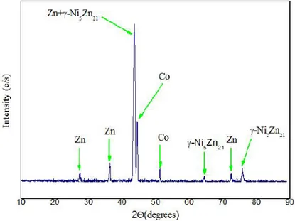
Figure (1) exhibits the diffractograms of Zn-Ni-Co alloys obtained at current densities 30 mA/cm2. The X-ray diffraction reveals that γ-Ni5Zn21 phase, Co matrix phase and pure zinc phase [13], are observed in the electroplating of Zn–Ni–Co alloy. Moreover, some new peaks appear at the which are the peak at 2θ of 44.59 ͦ and 51 ,37 ͦ that corresponds to Co phase, the peaks at 2θ of 43.69 ͦ and 64.36 ͦ and 75.88 ͦ that correspond to γ- Ni5Zn21[13], phase and the peaks at 2θ of 27.37ͦ and 36.4 ,43.6 ͦ and 72 .61 ͦ that correspond to pure Zn phase. from γ-Ni5Zn21 phase increases for the electroplating of Zn–Ni–Co in comparison with Zn–Ni alloy deposition. [14]. the γ-Ni5Zn21phase showed a preferential (330) and (411) crystal orientation as confirmed by previous work [15].
3.2.Surface morphology of coatings
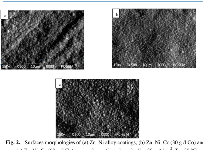
The plated coatings morphologies of the different compositions are illustrated in Fig. 2, The Zn-Ni alloy coatings showed a homogenous structure, It is clear that the grains size is decreased with the increase of cobalt content in the ternary Zn-Ni-Co deposits [16]. Consequently, the compactness, adherence and hardness increase with elevation of the Cobalt content .the three coatings were cover the substrate completely without cracks. It is noticeable that the greatest homogeneity and uniformity of the surface morphology of the Zn-Ni-Co coating with 50g/l Co,
Fig. 1. XRD patterns of electrodeposit Zn–Ni–Co alloy on steel from at 30 mA cm−2at 30.0 °C.
3.3. Effect of Cobalt content of the bath on coatings microhardness
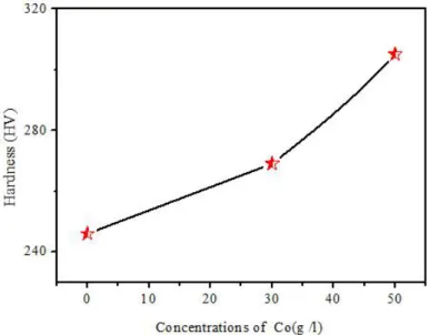
The microhardness results are showed in Fig. 3 and Table 2, showing the change in hardness of Zn–Ni alloy coating and the Zn–Ni–Co composite coatings with the variation of the cobalt concentrations, indicates that the microhardness of all Zn-Ni-Co composite coatings is considerably high than the Ni–Zn alloy coatings[16], The hardness increased from 246 Hv for Zn–Ni [8], alloy to 350 and 383 Hv for 30 and 50 g /l Co composite coating respectively, Hardness enhancement with Co content can be correlated to the (i) formation of solid solution, (ii) phase composition (formation of two phase structure), and (iii) reduction in alloy grain size [17-19].
Table. 2.Values of micro-hardness Vickers hardness (HV) registered different composite coatings Coating Dureté (HV) Steel 167.7 Zn -Ni 246 Zn-Ni-Co (30 g /l) 269 Zn-Ni-Co ( 50 g /l) 305
Fig. 2. Surfaces morphologies of (a) Zn–Ni alloy coatings, (b) Zn–Ni–Co (30 g /l Co) and (c) Zn–Ni–Co (50 g /l Co) composite coatings deposited by 30 mA/cm2, T = 30 °C, and
pH 3-4,5 for 60 s. 3.4. Corrosion studies
Fig. 4 shows the Tafel plots of Zn–Ni alloy and Zn–Ni–Co composite coatings,Data on the
corrosion potential (Ecorr), corrosion current density (icorr) and polarization resistance Rp of Zn–Ni and Zn–Ni–Co alloys is summarized in Tables 3 , The corrosion resistance of the electrodeposited Zn–Ni alloy was also studied[8] , increasing the Co2+ concentration in Zn–Ni-Co alloys increases the corrosion resistance of the deposit ,This may be due to the
increase in the γ-phase ,In general, the ternary Zn-Ni-Co deposits showed higher corrosion
resistance in comparison with Zn-Ni deposits[16, 20,21].
Table. 3.The electrochemical parameters of Zn-Ni alloy and Zn-Ni-Co composite coatings
Ecorr corrosion potential, icorr corrosion density current, βa anodic Tafel slope, βc cathodic Tafel slope, Rp polarization resistance Coating Ecorr (mV) ICorr (mA/cm2) βa (mV) βc (mV) Rp (Ω cm2) Zn Ni Zn-Ni-Co (30 g /l) Zn-Ni-Co ( 50 g /l) -930,5 -916,7 -854,8 129,39 114,23 109,376 352,5 430,9 377,2 -233,5 -283,3 -319,6 524.43 491.63 501.47 a b c
Fig. 3. The effect of cobalt contents in the composite coatings on the hardness of deposits. Zn–Ni alloy and Zn–Ni–Co composite coatings
Fig. 4. Tafel plots of Zn–Ni alloy and Zn–Ni–Co composite coatings at different concentrations of Cobalt
3.5. Electrochemical impedance
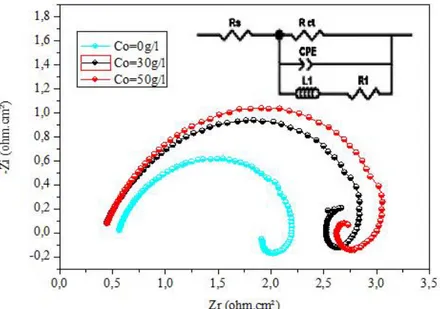
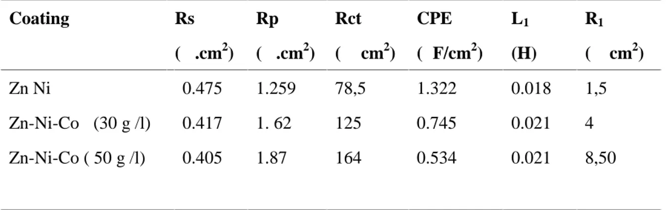
The electrochemical impedance spectre of Zn-Ni alloy coatings and Zn-Ni-Co alloys composites, as used for the potentiodynamic polarization experiments. Impedance measurements were made at open circuit potential applying an AC signal of 10mV in the frequency range 100KHz to 10MHz. The impedance results obtained from Nyquist plots for the samples used for corrosion tests in 3% NaCl solution are shownin Table 5 and Fig. 5. From Fig. 5, it is clearly seen that the cobalt concentration significantly affects both the high
and low frequency loops. The Nyquist plots indicate that the nature of electrical double layer and the adsorbed intermediate ions involved in electrodeposition process is changed by different cobalt concentrations of some researchers baths [22] In CPE is the constant phaseelement, Rctis the charge transfer resistance, R1and L1are elements associated with the inductive loop, and RS is the uncompensated solution resistance.The results show Zn-Ni-Co composites coating with 50 g/l concentration in the bath possesses a maximum value of Rct, thus it would show the high corrosion resistance . These results are compatible with the result of Tafel polarization measurements. The formation of a high nickel γ-alloy phase and codeposition of cobalt increase the corrosion resistance of the Zn-Ni-Co alloys composites. Cobalt codeposition in the alloy also tends to produce a fine grains size, as observed by SEM. [16]
Fig. 5. The Nyquist plots of Zn–Ni alloy coatings and Zn–Ni–Co alloys composite in different concentrations of cobalt.
3.6. Chronoamperometry studies
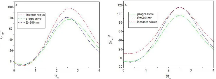
Chronoamperometry was used to study the electrocrystallization process of Zn–Ni and Zn–Ni–Co alloys composite. at potentials E=500mv . Fig. 7, the transients can be divided into two zones. We observe that the current density have a maximum value in the first zone, which is typical for the crystal nucleation and growth processes. During this stage, the nuclei develop diffusion zones around themselves. The second zone corresponding to the abrupt
drop in the current density, which is typical of a diffusion-controlled process , expressions for multiple nucleation phenomena followed by diffusion-controlled growth of three-dimensional islands developed by Scharifker and Hills. The resulting expressions for the normalized current densities allow distinguishing between instantaneous nucleation and progressive nucleation [23-27] according to Eq. (2) for instantaneous nucleation and Eq. (3) for progressive nucleation:.
The experimental and theoretical data for Zn–Ni alloy coatig and Zn–Ni–Co alloys composite shown in Fig. 7a and 7b. In these figures, Zn-Ni alloy coating deposition corresponds to three-dimensional progressive nucleation growth process with diffusion-controlled growth (Fig. 7a). For the Zn–Ni-Co alloys composite, the nucleation mode was closer to instantaneous nucleation (Fig. 7b).This difference may be explained by the adsorption of cobalt on the cathode surface which created additional active nucleation sites during electrodeposition on the mild steel substrate.
Table 5 Extracted fitted data from the equivalent circuit of Zn–Ni alloy coating and Zn-Ni-Co alloys composite in a 3 % NaCl solution
Coating Rs (Ω.cm2) Rp (Ω.cm2) Rct (Ω·cm2) CPE (μF/cm2) L1 (H) R1 (Ω cm2) Zn Ni Zn-Ni-Co (30 g /l) Zn-Ni-Co ( 50 g /l) 0.475 0.417 0.405 1.259 1. 62 1.87 78,5 125 164 1.322 0.745 0.534 0.018 0.021 0.021 1,5 4 8,50
Fig 6. Chronoamperograms of Zn–Ni alloy coating and Zn–Ni–Co alloys composite at potentials E=500mv, vs. Hg/HgO in a 3 % NaCl solution
Fig 7. Non-dimensional curves for electrocrystallization of (a) Zn–Ni alloy coating and (b) Zn–Ni–Co alloys composites (30 g /l Co), with instantaneous and progressive
4. CONCLUSION
The following conclusions were drawn:
XRD spectres illustrate the phase structure of composites coating was single γ -Ni5Zn21 phase and incorporation of cobalt in the Zn–Ni alloy coating decrease the grain size.
From the SEM images of the compsites coating morphologies the grains size decreases with the increase of cobalt content in the ternary Zn-Ni-Co deposits
The deposited coating with 50g/l Co showed the maximum value of hardness 305HV, because the increase of the Co2+concentration in the plating bath increases of micro-hardness
from Tafel plots the values of the corrosion current density (Icorr) decreases, the
corrosion potential (Ecorr) and the polarization resistance (Rp) increase with increasing
of Cobalt content in the electrolyte bath.
The data obtained from electrochemical impedance spectroscopy (EIS) assumes that Zn-Ni-Co composite coating with 50 g/l concentration in the bath possesses a maximum value of Rct, thus it would show the high corrosion resistance
Nucleation and growth proceesses are determined by Chronoamperometry electrochemical processes in the first moments following three-dimensional progressive nucleation growth processes with diffusion-controlled growth.
5. ACKNOWLEDGEMENTS
I would like to thanks “Responsible of laboratory of thin films and applications” for their assistance in the preparation of this work.
6. REFERENCES
[1] . C. Muller, M. Sarret, T. Andreu : Electrochimica Acta , V .48, No 17, 2003, p. 2397–2404, doi.org/10.1016/S0013-4686(03)00253-6
[2] . M. E. Bahrololoom, D. R. Gabe and G. D. Wilcox : Journal of The Electrochemical Society, V. 150, No. 3, 2003, C144-C151, doi: 10.1149/1.1545460
[3] . J. B. Bajat, V. B. Mišković-Stanković, M. D. Maksimović and D. M. Dražić : Electrochimica Acta, V. 47, No. 25, 2002, p. 4101–4112, doi .org /10.1016 /S0013-4686(02) 00418-8 .
[4] . H. Ashassi-Sorkhabi, A. Hagrah, N. Parvini-Ahmadi , J. Manzoori :Surface and Coatings Technology, V . 140, No.3, 2001, p.278–283.
[5] . R. Ramanauskas, L. Gudavičiūtė,,A. Kaliničenko, R. Juškėnas : Journal of Solid State Electrochemistry, V. 9, No .12, 2005, p. 900–908, doi:10.1007/s10008-005-0049-z. [6] . F. H. Assaf, A. M. A. El-Seidy, M. M. Abou-Krisha, A. A. Eissa; Journal of
Electrochemical Science , V. 10, No.7, 2015, p .5465 - 5478.
[7] . M. Diafi , S. Benramache ,E. Guettaf Temam, M. L .Adaika , B. Gasmi :Acta Metallurgica Slovaca, Vol. 22, 2016, No. 3, p. 171-180, doi: 10.12776/ams.v22i3.706. [8] . M. Diafi, N. Belhamra, H. Ben Temam, B.Gasmi, S. Benramache: Acta Metallurgica
Slovaca, Vol. 21, No. 3, 2015, p. 226-235, doi: 10.12776/ams.v21i3.472 .
[9] . M. Diafi, M. Omari: Boletín de la Sociedad Española de Cerámica y Vidrio, Vol. 51, No. 6, 2012, p. 337-342, doi: 10.3989/cyv.462012 .
[10] . R . Sekar , K . K . Jagadesh, G. N. K. Ramesh bapu: , Transcations of Nonferrous Metals Society of China, Vol.25, N.6 ,2015, p.1961−1967, doi:
10.1016/S1003-6326(15)63804-3
[11] . S. H. Mosavat, M. H. Shariat, M. E. Bahrololoom: Corrosion Science, Vol. 59, 2012, p. 81–87, doi:10.1016/j.corsci.2012.02.012.
[12] . W. Chen, W. Gao: Electrochimica Acta, Vol. 55, 2010, No. 22, p. 6865–6871, Doi:10.1016/j.electacta.2010.05.079.
[13] . M.M. Abou-Krisha , H.M. Rageh, E.A. Matter : Surface and Coatings Technology, Vol. 202, 2008, No. 15 , p .3739–3746, doi:10.1016/j.surfcoat.2008.01.015.
[14] . R. Noumi, H. Nagasaki, Y. Foboh, A. Shibuya : SAE Technical, Pap. Series No 820332, Detroit, Michigan, 1982, p. 22–26, doi:10.4271/820332.
[15] . S .Micin, S.Martinez, B.N. Malinovic, V. Grozdanic : journal of Chemical Technology and Metallurgy, V.51, 2016, No .5, p .556-562 ,
[16] . M.M. YOUNAN : Journal of Applied Electrochemistry, January , Vo. 30, 2000,No. 1, p. 55–60, doi: 10.1023/A:1003840519591
[17] . B. Bakhit, A. Akbari :Journal of Coatings Technology and Research , Vo . 10, 2013, No. 2, p .285–295, doi: 10.1007/s11998-012-9437-3
[18] . L .Wang, Y.Gao, Q .Xue, H. Liu, T. Xu : Applied Surface Science, Vo . 242, 2005, No. 3–4, p. 326–332, doi.org/10.1016/j.apsusc.2004.08.033
[19] . O. Hammami, L. Dhouibi, P. Bercot, E M. Rezrazi : Journal of Applied Electrochemistry, Vo.44, 2014, No.1, p. 115–121, doi:10.1007/s10800-013-0613-7 [20] . M. M. Abou-Krisha : Materials Chemistry and Physics, Vo. 125, 2011, No 3,
p.621–627, doi:10.1016/j.matchemphys.2010.10.007
[21] . N. Eliaz, K. Venkatakrishna, A. Chitharanjan Hegde: Surface and Coatings Technology, Vo. 205, 2010, No. 7, p.1969–1978, doi:10.1016/j.surfcoat.201.08.077 [22] . M. Zamani, A. Amadeh, S. M. Lari Baghal : Transactions of Nonferrous Metals
Society of China, Vo, 26, 2016, p. 484−491, doi: 10.1016/S1003-6326(16)64136-5 [23] . Z . Feng, Q. Li, J. Zhang, P. Yang, M. An, Journal of The Electrochemical Society,
V. 162, N (9), p .412-422, 2015, doi: 10.1149/2.0121509jes
[24] . S. Ghaziof, P. A. Kilmartin, W.Gao: Journal of Electroanalytical Chemistry, Vol .755, 2015, p. 63–70, doi: org/10.1016/j.jelechem.2015.07.041
[25] . B. Scharifker, G. Hills: Electrochim Acta, Vol. 28, No. 7, 1983, p. 879–889, doi:10.1016/0013-4686(83)85163-9
[26] . N. Eliaz, M. Eliyahu: Journal of Biomedical Materials Research Part A, 2006, p. 621–634, doi: 10.1002/jbm.a.30944
[27] . K. Raeissi, A. Saatchi, M.A. Golozar: Journal of Applied Electrochemistry, Vol. 33, 2003, No. 7, p. 635–642, doi: 10.1023/A:1024914503902
How to cite this article:
Diafi M, Degheche K, Ben Temam H. The influence of CO2+ concentration on the electrodeposition of znni films to obtain the ZNNI–CO composite coatings. J. Fundam. Appl. Sci., 2017, 9(1), 74-101.