Development of a Mesoscopic Cell Modeling the Damage Process in Steel at
Elevated Temperature
Sylvie Castagne, Marc Remy and Anne Marie Habraken
M&S Department, University of Liège, Chemin des Chevreuils 1, BE-4000 Liège, Belgium
Abstract
An on going project whose goal is the development and identification of a mathematical model of steel at elevated temperature using a mesoscopic approach is presented. The research aims to study the damage process at elevated temperature using information from the macroscopic and mesoscopic scales. As a final application our results will be used to study the industrial process of continuous casting of low carbon steel.
Keywords : Crack propagation ; creep ; damage ; high temperature ; steel
Introduction
This research studies steel at high temperature and aims to model damage using a numerical mesoscopic approach identified by experimental measurements obtained from the mesoscopic and macroscopic scales. Constitutive laws have been implemented into a finite element code. They will be applied to study the initiation and propagation of cracks in the industrial process of continuous casting.
For the studied low carbon steel, transverse cracking is recognized as a major problem in this process. Hot tensile tests have demonstrated that steel has a ductility gap in the temperature range from 1000°C to 600°C. This loss of ductility is responsible for the appearance of cracks during the bending and unbending operations of the strand. The austenitic grain boundary is a favorable place for cracks to begin. They appear by strain
concentration and microvoid coalescence at grain boundaries and by grain boundary sliding. The influence of creep, controlled by diffusion, is important in the studied temperature range.
The mathematical model development begins with a representative mesoscopic cell which is loaded by stress and strain fields determined by macroscopic experiments. Such an approach allows the identification of the
mesoscopic damage law. Mesoscopic cell
In order to represent intergranular creep fracture, the developed model contains solid finite elements for the grains and interface elements for their boundaries (see also [1]). Inside the grains, an elasto-visco-plastic law without damage is used, and at its boundaries, a law with damage is preferred.
Solid finite elements and grain representation.
The grains are modeled by thermomechanical 4-nodes quadrilateral solid elements BLZ2T of mixed type [2]. Fig. 1 shows an example of the mesoscopic representative cell. On the right part, a zoom on three grains allows to visualize the meshing of these grains and their interfaces.
Metallographic and texture analysis combining optical microscopy, scanning electron microscopy and
orientation image microscopy, as well as various chemical etching and visual observation on steel samples, have been performed at room temperature to determine the previous austenitic grain size and morphology. Hence the geometry of the mesoscopic cell is defined taking into account the results of this micrographic study.
A law of Norton-Hoff type (Eq. 1) is used to quantify the visco-plastic behavior inside the grain for the studied steel:
Compression tests of cylindrical samples have been performed after a thermal treatment aiming to reproduce the thermal cycle in continuous casting. Various strain rates and temperatures have been tested and compared with simulations in order to identify the parameters p1 to p4 dependant of temperature in this mechanical law.
Fig. 1. Mesoscopic cell with solid and interface elements.
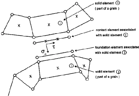
Fig. 2. Interface element: contact element, associated foundation, linked solid elements. The dots symbolize
nodes and the crosses represent integration points.
Interface finite elements and grain boundary representation.
The solid elements modeling the grains are connected by interface elements to account for cavitation and sliding at the grain boundary. As its thickness of the grain boundary is small in comparison with the grain size, the grain boundary is represented by one-dimensional interface elements. These elements are associated with a
constitutive law which includes parameters linked to the presence of precipitates, voids, etc. The damage variable explicitly appears in this law.
The interface element is composed of a modified contact element and a foundation element (see Fig. 2). For each integration point of the contact element, the program determines the associated foundation segment as well as the solid element to which the foundation is associated. The state variables for the interface element are computed using pieces of information of the two solids elements in contact (elements i and j in Fig. 2). The state variables in the interface element are the corresponding mean values at the integration points of elements i and j. This is obviously a rough approximation. Better schemes will be tested in the near future.
The original contact element is described in [3] and is usually combined with a Coulomb friction law. This element has been modified in order to introduce a new interface law and a cohesion criterion. The stress components of the interface element are represented in Fig. 2, their evolution is described by the following viscoeleastic-type relationships:
This is a penalty method where penalty coefficient ks and kn, are very large to keep the deviations ( ) and
( ) small, and are respectively the relative sliding velocity of adjacent grains due to shear stress τ and the average separation rate, normal to the interface and the foundation, due to damage growth. These variables are directly computed from nodal displacements. The evolution of (Eq. 3) and of (Eq. 13) are computed in the next section.
Interface law: evolution of the damage variable
The relevant damage mechanisms at the mesoscale are viscous grain boundary sliding, nucleation, growth and coalescence of cavities leading to microcracks. The linking-up process subsequently leads to the formation of a macroscopic crack.
Grain boundary sliding.
According to Ashby [4], grain boundary sliding is governed by:
where is the relative velocity between two adjacent grains, w is the thickness of the grain boundary and ηBis
the grain boundary viscosity. However in [1], ηB/w is expressed in term of the strain-rate parameter defined as
follows:
with d a length parameter related to the grain size, n the creep exponent. σ0, are reference stress and strain-rate.
Grain boundary cavitation.
In the context of damage at high temperature, the mechanism of voids nucleation, growth and coalescence is established.
In most engineering alloys, cavities have been observed to nucleate continuously. The following experimental relation has been suggested [5]:
where N is the average number of cavities per unit length of grain boundary, is the effective creep strain rate, σn the normal stress, introduced to allow a faster nucleation on those grain boundaries which are perpendicular to
the loading direction, and β a material constant. For the second formulation, Fn is the nucleation parameter of the
material and ∑0 a normalization constant. Fn is the microstructural parameter which influences the nucleation
rate at the grain boundary. Through this parameter, we can introduce zones where the nucleation is more important, to take into account the precipitation state for instance. According to Eq. 5, the nucleation will begin with the plastification. Nevertheless, experimentally, nucleation appears sometimes later, that is why we have to introduce a threshold to indicate the beginning of the nucleation. We define the parameter S which combines the stress and the cumulated strain:
This parameter S characterizes the state of the material before nucleation. It will grow with the strain and when the threshold value is reached, nucleation begins and the parameter S has no more utility. To define the threshold value Sthr, we suppose that it is related to a minimum cavity density Nl from which nucleation can be observed
and a factor Fn indicating the importance of the nucleation activity of the material:
Finally, experience shows that the cavity density tends to saturate for large creep strains, thus we will suppose that nucleation of new cavities stops when N reaches the value Nmax. If 2b is the cavity spacing, N is related to it
by N=1/π b2
The nucleation rate is related to the internal state of the material N as well as to the stress σn and strain rate
states on the grain boundary. With a one-dimensional element, this nucleation rate N can be interpreted as a measure of the rate of evolution of the cavity spacing . This equation can be used to compute the decrease rate of b due to continuous nucleation of cavities.
A detailed formulation of the cavity growth under diffusion and creep deformations can be found in [6]. A summary is proposed in Liu et al. [7] and reported hereafter. An idealized formulation of the grain boundary geometry is used: the cavities are supposed to be uniformly distributed with an average spacing of 2b and a diameter of 2a. For the proposed idealized boundary geometry with a cavity tip angle 2Ψ ≈ 75°, the cavity growth rate is:
where h(ψ)= [(1 + cosψ)-1 -0.5cosψ]/sinψ (shape function of the cavity) and is the total cavity volume growth rate, which is divided into diffusion growth and creep deformation :
where D is a constant related to the material diffusion, n the creep exponent, σn, σe and σm are respectively the
normal, effective, and mean stresses applied to the grain boundary. The variable f is defined as follows:
The coupling between diffusive and creep contribution to void growth is introduced trough the length scale L: for small values of a/L, cavity growth is dominated by diffusion while for larger values, creep growth becomes more and more important. Finally the discrete cavity distribution is replaced by a continuous distribution on each facet of the grain boundary so that the cavity volume V and the average separation between two grains δC evolve
in a continuous way on the facet. Then, the separation rate is given by:
The coalescence takes place when cavities are sufficiently close to each other to collapse. At this moment, the crack begins to propagate and the interface elements are no more in contact. For Onck [1], the parameter used to define the coalescence activation is the ratio a/b. We call it a damage variable in our model. When this ratio reaches the value 0.7, coalescence is triggered and crack appears.
First application
The growth of a crack for the simple model of Fig. 3a has been simulated as a first application. With this first example, the stability of the code when a crack is propagating has been analyzed. Up to now, the parameters for the interface law are issued from [1] but we have at our disposal results of a damage experimental study allowing the identification of the interface law for our steel [8], this work is in progress. For the continuous zone we simply used an elastic law with an elastic modulus of 32400 MPa which correspond to the elastic modulus of steel at 900°C.
Fig. 3. a) Loads and fixations. Stress maps (σy): b) without interface element, c) with interface elements ks = kn =
100000 (MPa/mm), d) and ks = kn = 10000 (MPa/mm).
The three other pictures of Fig. 3 illustrate the effect of the penalty coefficients ks and kn. In each of them, the
stress σy (MPa) in the direction perpendicular to the interface zone is represented. At this moment, no crack has
appeared but voids are already growing in the interface. Fig. 3b is a reference case with no interface element. In Fig. 3c interface elements have been introduced, ks = kn = 100000 (MPa/mm) and in Fig. 3d ks = kn = 10000
(MPa/mm). The presence of interface elements introduces a softer zone in the mesh. Of course, this effect increases if the penalty coefficients decrease. For the small penalty coefficients, the perturbation is more important and introduces a stress concentration even when the interface is still in contact. The interface seems to be already open but this is only due to the penalty method, the criterion which indicates crack appearance has not yet been reached. In conclusion, we have to take the first values for the penalty coefficients, keeping in mind, however, that too high coefficients could introduce convergence problems.
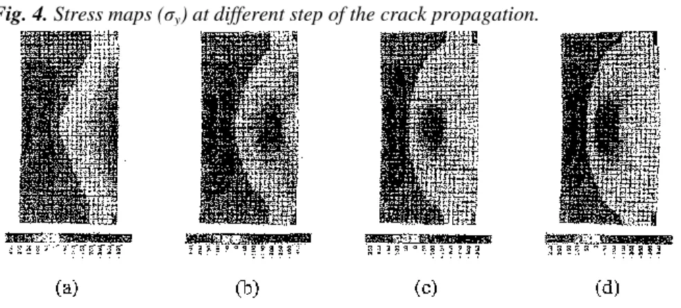
Fig. 4. Stress maps (σy) at different step of the crack propagation.
Fig. 4 shows the evolution of the crack for ks = kn = 100000 (MPa/mm). Fig. 4a is identical to the one presented
in Fig. 3b. In Fig. 4b the crack has propagated on 4 elements. In Fig. 4c the propagation extends on 8 elements. In Fig. 4d all the interface elements are opened. The stress concentrates around the crack tip and decreases in the right half part as the crack propagates.
Conclusions
The research is dedicated to a mesoscopic study of damage at high temperature of micro-alloyed steel for continuous casting. The development of the damage model is progressing in parallel with the analysis of the experimental tests.
We have succeeded in using our interface element to model crack propagation in a simple test and the results were very encouraging. The next step is to apply it to more complex cases and to identify the damage parameters using the damage experimental study.
Acknowledgements
S. Castagne and A.M. Habraken thank the National Fund for Scientific Research of Belgium (FNRS) for its support. Industrial partners ARCELOR and its research teams IRSID and the Technical Direction of Cockerill Sambre are acknowledged.
References
[1] P. Onck and E. van der Giessen: J. Mech. Phys. Solids Vol. 47 (1999), p 99 [2] Y. Zhu and S. Cescotto: Int. J. Num. Meth. Eng. Vol. 38 (1995), p 685
[3] A.M. Habraken and S. Cescotto: Mathl. Comput. Modelling, Vol. 28 (1998), p 153 [4] M.F. Ashby: Surface Sci. Vol. 31 (1972), p 498
[5] E. van der Giessen and V. Tvergaard: Acta Metall. Vol. 42 (1994), p 959 [6] V. Tvergaard and V. Needleman: Acta Metall. Vol. 32 (1984), p 157
[7] Y. Liu, Y. Kageyama and S. Murakami: Int. J. Mech. Sci. Vol 40 (1998), p 147
[8] S. Castagne, Damage in continuous casting of steel: towards a microscopic representative cell (DEA Graduation Work, University of Liège, 2001)