STUDIU ANALITIC ASUPRA REZISTENȚEI LA ÎNTINDERE A BETONULUI
ANALYTICAL STUDY ON TENSILE STRENGTH OF CONCRETE
RAHMAT MADANDOUST , MOSTAFA KAZEMI, SEDIGHE YOUSEFI MOGHADAM
Department of Civil Engineering, University of Guilan, P.O. Box 3756, Rasht, Iran
In the present numerical study, an attempt is made at a comparative analysis, in terms of tensile strength of concrete, among the modulus of rupture test, Brazilian splitting test and concrete direct tension test. In direct test method, two aligned steel bars were placed in a cylindrical specimen to transmit the uniaxial force to the concrete specimen. The tensile strength of concrete affects the behavior of concrete structure. Drawing on this, estimating true tensile strength, as one of the basic properties of concrete, is headed by researchers. The present study intends to analyze tensile strength tests of concrete by means of finite element (FE) method employing ABAQUS software. The accuracy of the FE models is confirmed using outputs of previous experimental studies. Results indicate that although all these tests are usually used to estimate the tensile strength of concrete, modulus of rupture and Brazilian splitting tests investigate better behavior of concrete in tension and the results of which are also more reliable than those of concrete direct tension test. Furthermore, it seems that the steel bars in direct tension test affect the stress distribution.
Keywords: tensile strength of concrete, FE analysis, fracture zone, tensile damage 1. Introduction
Nowadays, there exist several methods to determine strength of concrete. The fracture mechanics of concrete can be investigated by using each of these methods and can estimate the strength of concrete. On the other hand, concrete materials have been known for their abilities in compressive strength and have lower tensile strength and even though it is avoided to apply tensile load in design of concrete structures, the propagation of tensile stress sometimes is not negligible and even the concrete behavior is dominated by tensile cracking. Tensile strength, as an important property of concrete, plays a key role in the structural safety. The presence of cracks or flaws is the leading cause of high stress concentrations and is the reason why tensile strength is far less than compressive strength. Many factors have been known to affect the tensile strength of concrete for instance size, age, the level of stress and so forth. In order to assess tensile strength of concrete, some methods have been proposed. Concrete direct tension test is known as a method for directly measuring tensile strength of concrete. In this method, load was applied along the longitudinal axis
of the concrete cylindrical specimen via two#6steel
bars which are embedded in test specimen and it causes failure, perpendicular to load direction. Although this method evaluates direct tensile strength of concrete, Modulus of rupture and Brazilian splitting tests have been accepted as
indirect methods for estimating tensile strength of concrete in ASTM C78 [1] and ASTM C496[2], respectively. A review of past studies indicates that numerous works were conducted on tensile strength tests of concrete, but little attention has so far been paid to compare them numerically. The present study comprises numerical modeling of concrete to better understand concrete behavior in tension using direct and indirect methods.
2. Description of models properties
Three crack models are available in ABAQUS software for simulating concrete elements including concrete smeared cracking, brittle cracking, and concrete damaged plasticity (CDP) [3]. Of these three models, since the CDP model is suitable for both nonlinear compressive and tensile behaviors, this technique was selected in the present study. Concrete behavior considered by this model is shown in Figure 1. Some properties were defined for establishing CDP model in ABAQUS as shown in Table 1. [4-6]. In order to define the concrete compressive behavior in ABAQUS, the modified Hognestad stress-strain formulation [7] was used. (Fig. 2) The compressive strength of concrete was 40MPa, while elastic modulus was 35.2 GPa. On the other hand, for all of numerical models,
three-dimensional (3D) hexahedral element, with 8nodes
and reduced integration(C3D8R)was used for the ABAQUS analysis.
Autor corespondent/Corresponding author, E-mail: [email protected]
Fig. 1- Concrete response under uniaxial loading in tension(a) and compression(b) [8]
Table 1 Parameters Used in CDP
Dilation angle Eccentricity F /F K Viscosity parameter
31° 0.1 1.16 0.67 0.0001
Fig. 2 - Modified Hognestad stress-strain model for concrete.
Fig. 3.- Mesh configuration for concrete direct tension test.
2.1. Concrete direct tension test
In this part, as shown in Figure 3, a 3D finite element (FE) model of a concrete cylindrical specimen and two steel bars were modeled with ABAQUS. According to the experimental method, the concentrated load should be applied at both
ends of concrete cylindrical specimen via two steel bars. Based on the study done by Lin et al. [9], the dimensions of concrete direct tension test specimen are 150 mm in diameter and 300 mm in length, used in ABAQUS model.
2.2. Modulus of rupture test
Five sections were generated in this model composed of the concrete specimen, two steel rollers as supports and also two semi-cylindrical steel samples, shown in Figure 4. The constraint of tie was determined the interaction between different parts. The uniform surface load was applied on semi-cylindrical steel samples. Also dimensions of concrete specimen used in ABAQUS model are510mm× 150mm × 150 mm following ASTM C78 [1].
2.3. Brazilian splitting test
The concrete cylindrical specimen, a steel plate and also thin steel, for applying load, were generated in this model and it is shown in Figure 5. The property “Tie” was used for the relationship between concrete specimen and other sections. The distributed load was applied on thin steel
according to ASTM C496[2].In order to mesh
concrete cylindrical specimen, first, the approximate
global size of the elements was considered 10 mm on the edge of circular cross-section. Later on, the mesh was refined automatically for FE analysis.
Fig. 5 - Mesh configuration for Brazilian splitting test method.
10 percent. Also, both curves nearly have a similar slope. Furthermore, in Figure 7, the contour plot of tensile damage variable (DAMAGET) shows that the crack propagation is the same location as Lin et al. [9] observed.
Fig. 6 - Comparison of laboratory measured and 3D numerical model of concrete direct tension test.
3.2. Modulus of rupture test
The experimental test, done by Siringi et al. [10], was used to validate the developed FE model based on the modulus of rupture-displacement curve. Figure 8 shows that failure load and displacement in experimental study are about 2 and 7 percent, respectively, more than those in numerical model. Furthermore, although the curve
Fig. 7 - Comparison of failure mechanism of concrete direct tension test in experimental and numerical specimen
3. Verification of FE model 3.1. Concrete direct tension test
To verify numerical model, the products of experimental study, performed by Lin et al. [9], were used. A plot of tensile strength against strain is shown in Figure 6, comparing numerical and experimental studies. Not only do both numerical model and experimental specimen have the same maximum tensile strength, but also differences in ultimate strain between two results were less than
slope of the numerical results, at the beginning of applying load, is a bit more than that of experimental results, later on, the numerical curve shows the same trend as experimental curve. Minor differences between numerical and experimental curves might be due to the increased initial stiffness of the numerical model which can be overlooked. In addition, the manner of propagation of damage is shown numerically as Siringi et al. [10] witnessed experimentally (Fig. 9). 0 0.5 1 1.5 2 2.5 3 3.5 4 0 100 200 300 Experimental Numerical
Strain (10¯⁶)
Te
ns
ile
st
re
ss
(M
Pa
)
Fig. 8 - Comparison of laboratory measured and 3D numerical model of modulus of rupture test.
Fig. 10 - Comparison of laboratory measured and 3D numerical model of Brazilian splitting test method.
Fig. 9 - Comparison of failure mechanism of modulus of rupture test in experimental and numerical specimens
Fig. 11 - Comparison of failure mechanism of Brazilian splitting test in experimental and numerical specimens 3.3. Brazilian splitting test
Based on an experimental study done by Indriyanto and Nuroji[11], as presented in Figure 10, experimental results and numerical model were compared to each other. Numerical results are indicative of the fact that the failure load is 201 KN, and the corresponding displacement is 0.151 mm, while for the experimental model, the failure load is 210 KN, and the corresponding displacement is 0.161 mm. As shown in Figure 10, at the beginning of applying load, the numerical results slightly overestimate the strength of the concrete specimen
compared to experimental results, but later on, the curve of numerical results gradually gets closer to that of experimental data. This might be due to increased initial stiffness of the numerical model at the beginning of applying load. Regarding this, the numerical curve has a good compatibility with experimental curve. In addition, the damage of FE model was observed at the same region as expected in experimental study (Fig. 11).As a result, both experimental and numerical specimens behaved similarly. 0 1 2 3 4 5 6 0 0.25 0.5 0.75 1 1.25 1.5 Experimental Numerical
Displacement (mm)
M
od
ul
us
o
f R
up
tu
re
(M
Pa
)
0 50 100 150 200 250 0 0.05 0.1 0.15 0.2 Experimental NumericalLo
ad
(K
N
)
Displacement (mm)
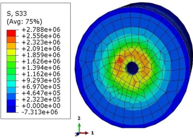
Fig. 12 - Stress distribution of concrete direct tension test in the middle cross-section using FE model.
Fig. 13 - Stress distribution of modulus of rupture test using FE model.
Fig. 14 - Stress distribution of Brazilian splitting test using FE model.
4. Investigation of tensile strength values in concrete tensile tests
Figures 12 through 14 give
allstresscontours related to tensile strength tests of
concrete in MPa. According to middle cross-section of concrete direct tension test (Fig. 12), in the first step, maximum tensile stresses happen in the center of concrete cylindrical specimen where the steel bars are located. In the next steps, surrounding area of the center of concrete section participates in carrying some of the bearing forces. According to Figure 12, the maximum tensile stress occurred in the middle portion of the specimen was found to be roughly 2.8 MPa. This value was also obtained from
Philips and Zheng [12] equation, predicted in experimental study. The investigation of contours of the modulus of rupture test (Fig. 13) shows that at first, the maximum stresses happen at the base of the middle of span. Following that, the value of stresses increases in the same region. Finally, with increasing the force and happening damage, the specimen is interrupted in middle span. As per ASTM C78[1],the measured modulus of rupture is about 10 to 15 percent of compressive strength, depending on strength level. Also, according to numerical studies (Fig. 12),the maximum tensile stress by modulus of rupture is 4.25 MPa. In Brazilian splitting test (Fig. 14), at the beginning of applying load, compressive stresses are generated in the upper and lower part of concrete cylindrical specimen. Later on, with increasing load, tensile stresses increase in the center of concrete cylindrical specimen more and more and this process causes the failure through applying load. The results of splitting tensile test of concrete, generated perpendicular to fracture zone, is 3.01 MPa. Stress distribution for Brazilian splitting test at in fracture zone is in accordance with ASTM C496[2] where a significant compressive stress in the transverse direction is observed at the top and bottom of cross-section and it equals to 15 MPa approximately. According to results mentioned above, as it is expected, failure zones can be predicted
properly usingstresscontours.
5. A comparison of FE modeling among concrete tensile tests
According to numerical studies, the direct tensile strength was found to be about 7% of compressive strength where the ratio of the flexural and splitting tensile strengths to the compressive strength was determined to be about 11 and 8 %, respectively. These results show that flexural and splitting tensile strengths were higher than the direct tensile strength.
To study the tensile strength of concrete, it should be considered as the concrete is a brittle material, a test will be more reliable if by means of which the stresses could be propagated better and concrete specimen in failure zone prevented from stress concentration. As shown in Figure 12, in concrete direct tension test, it seems that the steel bars affect the value of tensile strength of concrete because of the stress concentration near the center
of concrete specimen in failure zone. This matter
seems to account for why the tensile strengths estimated by Zheng et al. [13], Philips and Zheng [12] and Li et al. [14] vary noticeably. The results obtained from the FE model show that, although modulus of rupture and Brazilian splitting tests, as two methods in ASTM standard test methods [1,2],
investigate tensile strength of concrete indirectly,
the value of tensile strength of concrete in this two methods is more reliable than concrete tested in directly.
6. Conclusion
In this paper, three concrete tensile test methods containing concrete direct tension, modulus of rupture and Brazilian splitting tests were investigated numerically for estimating tensile strength of concrete and their behaviors were considered numerically. The following conclusions can be drawn from this investigation:
1. All data are indicative of the fact there exists a fair
agreements between numerical and
experimental results. Furthermore, the results demonstrate that FE models can predict the
fracture zones similar to experimental
observations and the contours of damage reveal that the fracture mechanisms of concrete tensile tests involve tensile damage evolution modes. 2. The result indicated that the ratio of the maximum
tensile stress by modulus of rupture test and Brazilian splitting test to concrete direct tension test was determined to be 1.5 and 1.1, respectively.
3. In concrete direct tension test, the steel bars cause the stress concentration near the center of concrete specimen in failure zone. This matter causes the perimeter of section in failure zone seems not to be effectively participate in load-carrying capacity of concrete specimen.
4. In modulus of rupture test and Brazilian splitting test, the maximum values of tensile stresses take place away from the places of loading. Therefore, loading equipment of indirect methods do not cause stress concentration in failure zones. 5. Modulus of rupture and Brazilian splitting tests,
being operated efficiently to estimate tensile strength of concrete, were proved to outperform concrete direct tension test.
REFERENCES
1. ASTM Standard C78, Standard test method for flexural stre ngth of concrete (using simple beam with third-point loading), Annual Book of ASTM Standards, American Society for Testing and Materials, 2009, West Conshohocken, PA.
2. ASTM Standard C469, Standard test method for splitting ten sile strength of cylindrical concrete specimens, Annual Book of ASTM Standards, American Society for Testing and Materials, 2002. West Conshohocken, PA.
3. D. Hibbitt, B. Karlsson and P. Sorensen, ABAQUS Theory and user’s manual, 2011, Version 6.11.3.
4. K.E. Barth, H. Y. Wu, Efficient nonlinear finite element modeling of slab on steel stringer bridges, Finite Element Analysis Design, 2006, 42 (14-15), 1304.
5. T. N. Huu, S.E. Kim, Finite element modeling of push-out te sts for large stud shear connectors, Journal of Constructio- nal Steel Research, 2009, 65 (10–11), 1909.
6. J. Lee, G. L. Fenves, Plastic- damage model for cyclic loading of concrete structures, Journal of Engineering Mechanics, 1998, 124 (8), 892.
7. E. Hognestad, A study on combined bending and axial load in reinforced concrete members, University of Illinois Engineering Experiment Station, Report: University of Illinois Engineering Experiment Station, No.399, 1951.
8. J. Lubliner, J. Oliver, S. Oller and E.Onate, A plastic- damage model for concrete, International Journal of Solids Structures, 1989, 25 (3),299.
9. Wei-Ting. Lin, An. Cheng, Ran. Huang and Tsan-Ching Cheng, A method for testing the strength of concrete using uniaxial direct tension, Journal of the Chinese Institute of Engineers, 2013, 36(3), 295.
10. Gideon. Siringi, Ali. Abolmaali and Pranesh B. Aswath, Properties of Concrete with Tire Derived Aggregate Partially Replacing Coarse Aggregates, The Scientific World Journal, 2015, 1
11. Bobby Rio. Indriyantho and Nuroji. Finite element modeling of concrete fracture in tension with the Brazilian splitting test on the case of plane-stress and plane-strain, Procedia Engineering Journal, 2014, 95, 252.
12. D. Phillips and B. Zheng, Direct tension tests on notched and un-notched plain concrete specimens, Magazine of Concrete Research, 1993, 145(162), 25.
13. W. Zheng, K.H. Kwan and P.K. Lee, Direct tension test of co ncrete, ACI Materials Journal, 2001, 98(1), 63.
14. Q. Li, Y. Duanand G. Wang, Behavior of large concrete specimens in uniaxial tension. Magazine of Concrete Research, 2002, 54 (5), 385.
![Fig. 1- Concrete response under uniaxial loading in tension(a) and compression(b) [8]](https://thumb-eu.123doks.com/thumbv2/123doknet/5654854.137003/2.892.170.749.100.357/fig-concrete-response-under-uniaxial-loading-tension-compression.webp)