Abstract
Since the early seventies, potential health risks from Extremely Low Frequency (ELF) exposure (50 Hz) have
been extensively treated in the literature (more than 1000 references registered by WHO
1, 2007). After 30 years
of worldwide research, the major epidemiological output is the possible moderate increased risk (by a factor 2)
of childhood leukaemia in case of a long exposure to an ambient magnetic flux density (B-field) higher than 0.4
µT. However, this fact has not been confirmed by in vivo and/or in vitro studies. Moreover it has not been
validated by any adverse health biological mechanisms neither for adults nor for children. Nobody knows
precisely what happens inside the body and what could be a hazardous health effect of the ELF fields at 50 Hz.
International recommendations (ICNIRP
2) are currently, for general public, not to exceed a B-field of 100 µT (50 Hz)
and an E-field of 5 kV/m (50 Hz).
The authors are looking for a signal generated in the biological process under electric interactions.
Herein, a rough overview of typical values of ELF fields will be presented followed by a brief literature survey
on childhood leukaemia and ELF. The potential carcinogenic effect of ELF would be linked to electrical
distur-bances in cell behaviour. The major concern linking childhood leukaemia and ELF is thus to determine the
res-ponse of bone marrow cells under ELF fields. With that purpose, transmembrane potential will be targeted and
linked to the E-field at that level.
This paper is three-folded:
First, the electric interactions between ambient ELF fields and the body are studied both qualitatively and
quantitatively. Though no adverse health field threshold is defined, a minimum field level is fixed in order to
discriminate inherent random noise, in agreement with NIEHS
3. This is based on the fact that mechanisms
become only plausible under field exposure above a certain strength.
Different sources of internal E-field are analysed and classified according to their potential risk.
Second, the hypothesis of contact current is detailed.
Finally, key actions to undertake are highlighted. Based on the current state of the art and some authors’ own
developments, this paper proposes simple low cost modifications of private electrical installations in order to
annihilate the major source of potential effects of ELF.
Particular emphasis is paid to the situation in Belgium as the authors are part of the BBEMG (see end note)
and perform numerous measurements in Belgian residential homes.
Effects of extremely low frequency
electromagnetic fields (ELF) on
human beings
An electrical engineer viewpoint
J. L. Lilien, Pr., P. Dular, Research Fellow, R. V. Sabariego, Dr., V. Beauvois, Ir., P. P. Barbier, R. Lorphèvre, PhD Students University of Liège - Dept. of Electrical Engineering and Computer Science, Institut Montefiore – Sart Tilman B28 – B-4000 Liège (Belgium)
1 WHO: World Health Organisation.
2 ICNIRP: International Commission on Non-Ionising Radiation Protection. 3 NIEHS: National Institute for Environmental Health Sciences (USA).
Samenvatting
Sinds het begin van de jaren zeventig werden de mogelijke gezondheidsrisico’s te wijten aan zeer lage frequentie
(ELF) velden (50 Hz) uitgebreid in de literatuur behandeld (meer dan 1000 referenties geregistreerd door
de WGO
1in 2007). Na 30 jaar wereldwijd onderzoek, leidt de meest bepalende epidemiologische output tot
de mogelijkheid van een gering toenemend risico (met een factor 2) bij kinderleukemie in geval van lange
bloot-stelling aan een magnetische fluxdensiteit (B veld) van meer dan 0,4 µT. Nochtans werd deze vastbloot-stelling niet
bevestigd door in vivo en in vitro studies. Bovendien werd ze niet gevalideerd door een of ander schadelijk
biologisch mechanisme noch bij volwassenen noch bij kinderen. Niemand weet wat er exact gebeurt in het
lichaam en wat een schadelijk effect van ELF velden op 50 Hz zou kunnen zijn.
Internationale aanbevelingen (ICNIRP
2) m.b.t. de blootstelling aan het publiek zijn, vandaag, de waarde van
100 µT (50 Hz) voor het B veld en van 5 kV/m (50 Hz) voor het E veld niet te overschrijden.
De auteurs zoeken naar een signaal in het biologische proces opgewekt door elektrische interacties.
Eerst wordt een ruw overzicht van typische waarden van ELF velden voorgesteld, gevolgd door een beknopte
literatuurcompilatie over kinderleukemie en EMF
3.
Het mogelijke kankerverwekkende effect van ELF EMF zou gekoppeld zijn aan elektrische storingen in het
celgedrag. Voorzover kinderleukemie betrokken kan worden, is het zeker de moeite waarde zich op beenmergcellen
te focussen. Er zal, meer bepaald, op het transmembraan potentiaal verbonden met het E veld gemikt worden.
Dit artikel bestaat uit drie delen:
Eerst worden de elektrische interacties tussen de bestaande ELF velden en het lichaam zowel kwalitatief als
kwantitatief bestudeerd. Hoewel er geen schadelijke velddrempel gedefinieerd is, wordt er een minimaal
veld-niveau bepaald om, in overeenkomst met NIEHS
4, de achtergrondruis te elimineren. Dit is gebaseerd op het feit
dat mechanismen pas geloofwaardig worden vanaf het moment dat de veldblootstellingen een bepaald niveau
overschrijden. Verscheidene bronnen van inwendig E veld worden geanalyseerd en gerangschikt in functie van
hun potentiëel risico.
In een tweede stap wordt de hypothese van de contactstroom gedetailleerd.
Uiteindelijk worden de te ondernemen “key actions” onderstreept. Op basis van de huidige stand van zaken en
van eigen ontwikkelingen door sommige auteurs, worden in dit artikel eenvoudige aanpassingen van de elektrische
installaties van particulieren voorgesteld met de bedoeling de meeste bronnen van mogelijke effecten van ELF
velden te elimineren.
Bijzondere aandacht wordt besteed aan België, wetende dat de auteurs aan de BBEMG deelnemen (zie eindnota)
en veel metingen uitvoeren in Belgische woonhuizen.
1 WGO : Wereldgezondheidsorganisatie
2 ICNIRP: International Commission on Non-Ionising Radiation Protection 3 EMF : ElectroMagnetic Fields
4 NIEHS: National Institute for Environmental Health Sciences (USA).
Résumé
Depuis le début des années septante, les risques potentiels sur la santé résultant d'une exposition aux champs
électromagnétiques à basse fréquence (50 Hz) (ELF) ont largement été traités dans la littérature (plus de 1000
références répertoriées par l’OMS
1depuis 2007). Après 30 années de recherche, les études épidémiologiques ont
principalement mis en évidence une relation possible entre l’augmentation des leucémies infantiles (d’un facteur
2) et une exposition prolongée au champ magnétique ambiant supérieur à 0,4 µT. Pour l’instant, ces résultats n’ont
pas encore été confirmés ni par des études in vivo ni par des études in vitro.
A ce jour, aucun mécanisme biologique pathologique n’a pu être mis en exergue, que ce soit pour les adultes ou
pour les enfants. En fait, personne ne sait avec précision ce qui se produit à l'intérieur du corps et quel pourrait
être un effet des champs électromagnétiques à 50 Hz sur la santé.
L’ICNIRP
2recommande pour le grand public, de ne pas être exposé à des valeurs supérieures à 100 µT pour le
champ d’induction magnétique et à des valeurs supérieures à 5 kV/m pour le champ électrique.
Introduction
Ambient ELF fields
Origin of ELF fields
50 Hz electric (E) and magnetic flux density (B) fields are linked to any human activity as electricity has become the best energy vector in many applications with a relatively high global efficiency from well to wheel approach. Particularly, the transmission and distribution of electrical energy is done with about 95 % efficiency over thousands of kilometres.
The generation, delivery and use of electricity to transfer energy cannot be done without the presence of E- and B-fields. E is linked to the voltage and topology. B is linked to the load current and the topology. Three-phase 50 Hz AC (alternative) high voltage networks are used to optimise the type of material (aluminium or copper) and the size of the ROW (Right Of Way) for a given power transfer. 50 Hz is the AC fre-quency of these fields, that has been
chosen at the early beginning of elec-tricity (with two major actors, one having chosen 50 Hz in most of the world and the other 60 Hz mainly in America) as being close to the technical-economic optimum of transformer size and easy to manage at the power generation for the electrical machines. The frequency is closely linked to voltage drop which is also a key point along the line to ensure customers’ supply is in the 10 % range around the nominal value.
ELF fields order of amplitude near power lines and cables
It thus results in E- and B- fields in and around the lines and cables. E-field is extremely low inside conductors them-selves but both fields are very strong near conductors and then progressively decrease with the distance. The fields at a given point in the space are obviously the combination of the (vector) fields generated by any source in the vicinity, certainly including the major contribu-tion of each of the three phases of the network system. As the sum of the voltages and the sum of the currents
are zero in a balanced three phase transmission, the resulting far field is zero.
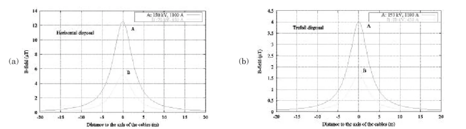
Fig. 1 shows values of B-field near the ground in the proximity of under-ground cables (E-field above the under-ground is obviously zero in such a case). Figs. 2 and 3 show specific data in Belgium for power lines (Hoeffelman et al., 2004). Of course, the loading of the line strongly influences the B-field value. The “max (calculated)” curve has been calculated for contingency limits (so called “N – 1” situation), an extremely rare case. We recommend taking into account the yearly mean values for health effect as long time exposure is concerned.
The value of B-field may be higher for underground cables at zero location (just over the path), as cables are buried at about 1.2 meter under the ground (compared to distance from ground about ten times more for aerial power lines) but decreases much quicker compared to aerial lines because of the proximity of the three phases.
Les auteurs de ce papier tentent de mettre en évidence les causes potentielles d’un signal significatif qui pourrait
être produit dans le processus biologique humain, soumis à des interactions électriques à basse fréquence.
Nous commencerons par exposer les valeurs types des champs électromagnétiques ambiants à basse fréquence puis
nous ferons un bref survol de la littérature traitant le sujet qui nous occupe, à savoir le risque potentiel de
leucé-mie infantile en relation avec les champs ELF. Les effets carcinogènes liés aux champs ELF sont alors reliés au
comportement électrique de la cellule et à sa perturbation potentielle. Les cellules de la moelle osseuse sont ciblées
prioritairement et le potentiel transmembranaire sera analysé en rapport avec le champ électrique interne (au
niveau de la cellule) résultant d’actions externes de champs ELF ou d’autres stimuli.
Ce document est divisé en trois parties:
D'abord, nous allons étudier les interactions électriques entre les champs électromagnétiques ambiants et le corps
humain. Bien qu'aucun seuil pathologique ne soit défini pour ces champs, nous allons considérer comme valeur
minimale les valeurs supérieures au bruit biologique, en accord avec le NIEHS
3. Ceci est basé sur le fait que les
mécanismes deviennent plausibles uniquement au-delà d’une certaine contrainte.
Différentes sources extérieures peuvent provoquer un champ électrique interne, ces sources seront analysées et
clas-sifiées selon leur risque potentiel.
En second lieu, l'hypothèse du courant de contact sera détaillée.
Finalement, des actions simples mais déterminantes seront mises en évidence pour limiter ces effets. En effet
l’état actuel de la recherche permet de proposer des modifications simples à faible coût à réaliser dans les
instal-lations électriques domestiques pour supprimer les effets potentiels des champs ELF.
Une attention particulière est apportée à la situation en Belgique car les auteurs font partie du BBEMG (voir note
de fin de papier, «end note») et ont réalisé un grand nombre de mesures dans le parc résidentiel belge.
1 OMS : Organisation mondiale de la santé
2 ICNIRP : Commission internationale de protection contre les rayonnements non ionisants 3 NIEHS : Institut national des sciences de santé environnementale (USA)
More details about curves for power lines and cables can be found in stan-dard IEC 62110.
A value of 1 m over the ground (or 1.5 m as in Fig. 1 to 3) is generally used in the literature as a reference level linked to actual values of the field in a place near the heart of any human being that could be there.
ELF fields in residential environment
E- and B-field sources may also be resi-dential installations as conductors going through the walls to the loads carry current (limited generally to max 25 A) and (generally phase to neutral) voltage (in Europe about 230 V). These two values are much lower (but their source is also much closer to human
beings) than those imposed by major power lines and cables as the latter are managing the whole flux into several ten thousands kilometres of distribu-tion line feeders. But a relatively strong B-field (several µTs) may be generated near the electricity counter or near large load in service, due to proximity, which is not the case in the middle of rooms.
Fig. 1: Typical B-field over underground cables, measured at 1.5 m over the ground
(A at 150 kV, 1100 A - B at 70 kV, 450 A) (a) horizontal disposal (0.25 m separation) (b) trefoil
(a) (b)
Fig. 2: Typical values for B-field in Belgium near HV lines as deduced from actual measurements (at 1.5 m above ground) and extrapolated to virtual values at different loading conditions (Hoeffelman et al., 2004).
Fig. 3: (a) Typical values for E-field in Belgium near HV lines (mid-span) as deduced from actual measurements (arithmetic mean and max values) (Hoeffelman et al, 2004), (at 1.5 m above ground). (b) Typical E-field pattern near power lines (at 1.5 m above ground).
Inhabitants may be either far (most likely) or close to power lines and cables and are thus subjected to different ambient fields.
Figs. 4 and 5 show the results of large measurement campaigns in residential houses in several countries.
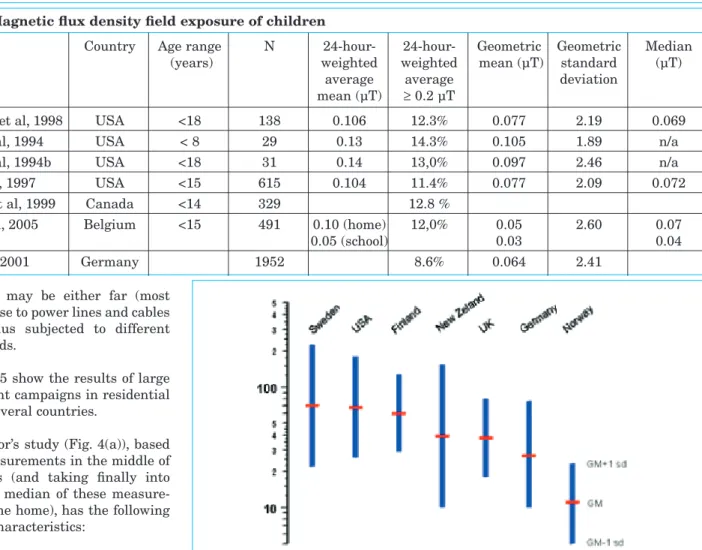
In the author’s study (Fig. 4(a)), based on spot measurements in the middle of some rooms (and taking finally into account the median of these measure-ments for one home), has the following statistical characteristics:
– Median1: 0.03 µT,
– Arithmetic mean value: 0.12 µT, – Geometric mean2value: 0.04 µT. The 24-hour exposition of children is of particular importance. Table 1 compiles the outputs of international studies (Foliart et al, 2001, WHO, 2007). These values have been obtained using dosimeters which are accompanying the children during the day and installed closed to their bed during the night.
Therefore, most of population in these countries is daily exposed to a mean B-field of about 0.1 µT (or 1 mG).
It must be pointed out that the authors’ study (Fig. 4 (a)), using spot measure-ments in the middle of the rooms, has found values that are of the same order of magnitude as those compiled in
Fig. 4: Residential magnetic fields in (a) Belgium (author’s study, 90 homes currently) (in µT, 1 mG = 0.1 µT) and in (b) USA (Syfers. 2006, taken from EPRI 1000 homes study) (in mG)
Fig. 5: Residential magnetic fields in some countries (in nT) (Swanson & Kaune, 1999). GM stands for “geometric mean” and sd stands for “standard deviation”.
Table I: Magnetic flux density field exposure of children
Study Country Age range N 24-hour- 24-hour- Geometric Geometric Median
(years) weighted weighted mean (µT) standard (µT)
average average deviation
mean (µT) ≥ 0.2 µT
Zaffanella et al, 1998 USA <18 138 0.106 12.3% 0.077 2.19 0.069
Kaune et al, 1994 USA < 8 29 0.13 14.3% 0.105 1.89 n/a
Kaune et al, 1994b USA <18 31 0.14 13,0% 0.097 2.46 n/a
Linet et al, 1997 USA <15 615 0.104 11.4% 0.077 2.09 0.072
McBride et al, 1999 Canada <14 329 12.8 %
Decat et al, 2005 Belgium <15 491 0.10 (home) 12,0% 0.05 2.60 0.07
0.05 (school) 0.03 0.04
Brix et al, 2001 Germany 1952 8.6% 0.064 2.41
1 The median is a number separing the higher half of a sample and from the lower half, in list of numbers arranging from the lowest value to the highest value, the median correspond to the middle one. 2 The geometric mean indicates the central tendency or typical value of a set of numbers. The geometric mean
is calculate using:
ln(
M
)
ln( )
x
n
G=
iΣ
(Decat et al, 2005) for “home” environ-ment (Table I).
Though such data is not available for the E-field, its value is generally limited to a few tens of V/m.
The population living near power lines is exposed to higher values, about a few µT for B-field and a few kV/m for E-field outside home; however the amount of people subject to such field levels is extremely limited. Also people living in the very near proximity of an electrical installation (i.e. distribution trans-former) may also be exposed to a few µT for distances smaller than about 5 m (as measured by the authors in many situations for distribution transformers up to 400 kVA). Farther than 5 m, the influence of the transformer can be neglected with regard to other sources. A side problem is linked to electric appliances, which may cause high fields. As stated by Leitgeb et al, 2008, the analysis of groups of devices showed a wide span of emission values of up to two orders of magnitude with only weak associations to power consumption. Many devices exceeded significantly ICNIRP’s reference levels (ICNIRP, 1998). A closer analysis is required to demonstrate conformity within reasonable limits.
Very few children are exposed in average to residential 50 Hz B-fields that exceed the field level linked to an increased incidence of childhood leukaemia, viz only 1 to 2 % are subject to field values higher than 0.4 µT (WHO, 2007).
Childhood cancer
This section is based on litterature survey (Wertheimer et al., 1979; Ahlbom et al., 2000, 2001; Brain et al., 2003; Dickinson, 2005; Greenland et al., 2000; Tenforde, 2000; WEB.11)
A cancer can be defined as an uncon-trolled growth of cells that may invade and disrupt surrounding tissues and spread through the body via the blood and lymphatic vessels. Carcinogenesis is a multi-stage process and is classically divided into two principal stages: initia-tion (mutainitia-tions in genes, irreversible) and promotion (reversible). The promo-tion needs to be sustained by repeated stimuli to the initiated cell. Promotion
then stimulates further development into a tumor (WHO, 2007, page 255). The aetiology of childhood leukemia is not yet fully understood. Nevertheless, there is a reasonably certainty indicating that often DNA damage before birth is often involved – probably in response to infection, chemicals, ionising radiations or other environmental factors. These pre-leukaemic cells are converted into overt disease after birth if children are susceptible – because of their genetic make up and early protection from infection – and experience one or fur-ther events (Dickinson, 2005).
The two types of cancer of concern in ELF field exposeure are childhood leukemia, namely acute lymphocytic leukemia (ALL) and brain cancer. There is a considerable epidemiological research on the association between power-frequency ELF and childhood leukemia dating from 1979 (Wertheimer and Leeper, 1979). Two relatively recent studies performed pooled analyses of magnetic fields and childhood leukemia (Ahlbom et al. 2000; Greenland et al. 2000). The highest exposure category was > 0.4 µT in the Ahlbom et al. study and > 0.3 µT in the Greenland et al. study. Both concluded that residential exposure in the highest exposure category increased the risk of childhood leukemia by about a factor of two. The control by several potentially confounding variables made little difference in the risk estimation.
IARC and US NIEHS concluded that the scientific evidence, in particular that related to childhood leukemia, sug-gests that power-frequency ELF is pos-sibly carcinogenic (category 2B). This conclusion was based on the evaluation that there is limited evidence of car-cinogenicity in humans and less than sufficient evidence of carcinogenicity in experimental animals.
Nevertheless, a cause-effect relationship cannot be inferred. For such moderate epidemiologic associations, data from laboratory studies is usually critical to determine whether a causal link exists. Laboratory evidence should also be complemented by an understanding of the mechanisms via which exposures interact with biological tissues. This has not been identified for ELF exposure.
The review of the epidemiological evi-dence of a link between exposure to ELF and childhood brain tumors allows concluding that there is no support for an overall association (Portier and Wolfe 1998; Kheifets et al 1999).
“The current epidemiological data represents the baseline, namely, an indication of a weak association only between ELF exposure and childhood leukaemia. The way forward to the resolution of this epidemiology uncer-tainty lies on defining a mechanism by which very weak ELF could induce a biological response, and with a clear demonstration of actual reproducible biological responses. To the best of our knowledge, there is nowadays satisfying experimental evidence that corrobo-rates that ELF do induce such responses” (said by M. J. Crumpton, Scientific Advisory Committee of the ELF Biological Research Trust).
Concerning ALL and its promotion (NOT initiation), repeated stimuli on initiated cells have to be located in the bone marrow.
Studies have shown (Cone, 1970, 1975, 1985) a modification of electrical properties of cancer cells in relation to the normal tissues that surround them. Many authors (Hazelwood et al, 1974; Cone, 1975; Cope, 1978; Brewer, 1985) have reported that cancerous cells are characterised by higher intracellular sodium, higher content of unstructured water, lower intracellular potassium, magnesium and calcium concentra-tions, and more negative charges on their cell surface. These abnormalities result in cancerous cells with lower transmembrane potentials (TMP) than normal cells and altered membrane permeability.
As a direct influence of typical external E- and B-field can hardly explain internal E-field over threshold, the hypothesis of indirect effects, through e.g. contact currents, is currently under evaluation.
Other diseases
Studies on miscarriage, neurodegenera-tive diseases (such as Alzheimer and Parkinson), breast cancer, and various cancers other than leukaemia have pro-duced either inconsistent or negative results.
Part 1: Electric interactions
between ambient ELF fields
and body - Qualitative and
quantitative approaches
Potential origins of biological effects
At 50 Hz and within the considered field levels, there are neither thermal effects nor any ionising radiation effects (WHO, 2007; WEB.13). Induced heat has been evaluated (WEB.13), for 100 µT and 1 kV/m 50 Hz ambient, near a very small fraction of µW (compared to endogenous 100 W generation). Ionising radiations (like X ray, gamma ray) are electromagnetic radiations that cause atoms to release electrons and become ions, owing to energy transfer from a photon3. That energy E (eV) is given by the formula E = h ⋅ f where “h” is the Planck constant4and f the frequency (Hz) of the electroma-gnetic wave (electromaelectroma-gnetic waves propagate in the air and vacuum at the speed of light). E is close to 1 eV5for the visible light (obviously non-ionising) and may reach billions of eV for X Ray (wavelength 1 nm). If the same formula is applied with f equal 50 Hz (wave-length 6000 km), the amount of energy is at least one billion times lower than for visible light, thus 50 Hz waves are non ionising radiations.
Electromagnetic fields can only act in human body through biological mecha-nisms, though.
When people are exposed to electric and magnetic fields created by power systems, imperceptible electric currents are induced in their bodies (see part III).
There are a lot of biological interactions linked to endogenous alternative cur-rents in the body, as electrocardiogram or electroencephalogram may easily show. The frequency content of the body signals is below 50 Hz (Alpha rhythms from 8 to 12 Hz, Beta rhythms 13 to 30 Hz, others (Delta, Theta) at much lower frequencies). The most well known is heart beat around 1 Hz.
In general, these signals are complex and far from being completely under-stood. Signals are exchanged between
cells owing to the change of TMP (transmembrane potential6). And this may be one source of disturbance due to non-endogenous signal (WHO, 2007, page 94; Wang et al, 2005; Chiu et al, 2005).
TMP may be disturbed by the internal E-field in the tissues and the latter is thus a key value to estimate potential disturbances. Concerning leukemia, the internal E-field in the bone marrow is of essential importance.
The spontaneous opening and closing of voltage-gated channels7 cannot occur for internal E-field lower than 10 mV/m (WHO, 2007, page 101).
Chiu & Struchly, 2005 determined that a local body internal E-field of 1 V/m (1000 mV/m, hundred times the WHO threshold) can produce 0.2 mV across the gap junction8 connecting two bone marrow stromal cells. These cells orchestrate hematopoiesis that includes lymphocyte precursor cellular9 prolife-ration (LeBien, 2000; Bertil et al, 2001). Thus, internal E-field, whatever the original source is, must be over several tens of mV/m to get a potential biologi-cal effect (which obviously would not necessarily come along with adverse health consequences).
There is nowadays no biological evi-dence indicating that such internal E-field within the bone marrow is either carcinogenic or stimulates the prolife-ration of initiated cells. However, there are some clues supporting the proposed hypothesis.
There is a secondary issue, concerning the duration of application of the “dis-turbance”. Up to now, we have no clear answer to that. Certainly a few seconds exposure would have no biological con-sequences as the auto-regulation mecha-nism is able to control most external attacks. Taking this phenomena into account, there are few ways to study transient short time effects, like ESD (electrostatic discharge) and electro-magnetic transient (due to switching impulse, lightning impulse...).
It is a recognized fact that even during ionising radiations; several hours are needed to provoke irreversible effects excepted for extremely high levels. It seems reasonable to consider at least a
similar duration to get potential effects with non ionising radiations.
We do not know if there is a dose-response effect and how to combine dif-ferent excitations at difdif-ferent time. More research on the subject is needed. Current investigations on epidemiolo-gical observations are based on mean 24 h exposure. A minimum of 8 h corre-sponding to sleep time is particularly concerned and thus bedrooms are the location where precautionary measures could be taken.
It must also be pointed out that it is extremely easy, for laboratory purposes, to apply a given E-field to Petri boxes with appropriate biological material. Unfortunately, only few labs performed such experiments.
First potential source of internal E-field: the human body response to direct effect of ELF fields
As just explained, the inside body locally induced internal E-field (due to either external E- or B-field) is of particular interest because it is related to the stimulation of excitable tissues.
E-field
Alternative external E-field, generally vertical (near ground) in typical situa-3The photon is the elementary particle
res-ponsible for electromagnetic phenomena. It is the carrier of electromagnetic radiation of all wavelengths.
4h = 6,6 10-34J.s = 4,1 10-15eV.s 51 eV = 1,602 10-19J
6Transmembrane potential is the difference
of potential between the outside and the inside of a cell. Human cells are delimited with a thin membrane. On that surface there are a lot of proteins, some of them com-pact together to form a small tube called connexine. When a cell with connexine meets another cell with connexine, they attach to form a small channel. Some ions and small molecules may diffuse through that small junction. Between the two connections, there is a little space called gap junction. This small canal may be open or close depending on the concentration of cal-cium and on the electric potential applied to this junction.
7Permeable membrane of a cell to ions, wich
is very sensitive to potential differences.
8Junction between cells allowing the
diffu-sion of small molecules and ions.
9 Cells that are the base of production of
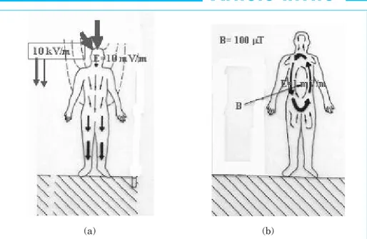
tions, induces alternative current paths (mainly vertical) in the body (Fig. 6(a)). Indeed alternative external E-field is strongly influenced by the presence of a body into the field. As a body is much more conductive than the surrounding air, there are charge distributions on its surface which partially annihilate the field inside the body. The internal E-field is quasi-null due to the joint effect of the external field and the induced surface charges. Due to the frequency (50 Hz), there is a permanent migration of charges which produces an alterna-tive current within the body. As these charges, and hence the current, depend on external conditions, there exist an internal E-field which corresponds merely to an ohmic voltage drop due to the resistivity (inverse of the conduc-tivity) of the body parts. The so-called “electrostatic induction current” follows more or less vertical paths through the body. Some of these paths go through the bone marrow.
In fact the E-field inside the body is about six orders of magnitude (1 mil-lion times) smaller than the external E-field: kV/m outside, mV/m inside. The order of amplitudes in the bone marrow (see later for further details) is of 10 mV/m for a body embedded in an external E-field of 10 kV/m.
B-field
Alternative external B-field induces a current in the body and thus an internal E-field (given by Ohm’s law) as in any conductive material. External B-field, horizontal in typical situations, induces current loops in the body (Fig.6 (b)). The order of amplitudes (see later for further details) of induced internal E-field is 1 mV/m for external B-E-field around 100 µT.
The order of amplitude of internal E-field (V/m) may be given by basic elec-tric laws. In a simple case of a circle of radius R (m), embedded in a perpendi-cular B-field (T) at a given frequency f (Hz), the induced E-field is determined by the following formula:
Ei=π ⋅ R ⋅ f ⋅ B
Corresponding current density J (A/m2) is given by Ohm’s law (σ being the con-ductivity in S/m):
J =σ ⋅ Ei
Both these values (due to E- and B-field) can be combined. The resultant is an internal E-field of some mV/m.
Could external ELF fields be directly linked to biological effects?
This is impossible in a typical situation in Belgium, even below a 400 kV power line (the maximum power line voltage level in Europe) at its maximum load transfer (typically 2.2 kA), or even over a 150 kV underground cable at its maxi-mum load transfer (typically 1.1 kA). Indeed these lines, as stated above, generate a maximum of rated B field (2.2 kA for 400 kV power lines) of 15 µT and a maximum of E-field of 9 kV/m, thus creating a combined value of inter-nal E-field lower than 10 mV/m. Even lower if we consider the recommended annual average values, for health effects.
A literature review of human beings in these situations is discussed in a next section in order to better quantify the internal E-field.
Other source of internal E-field: the contact currents
To limit the existence of internal E-field to external E-field and/or B-field is not exhaustive. There is another source
which has been first pointed out by Kavet et al, 2000, 2002, 2004, 2005; Bowman et al, 2006: the contact cur-rent.
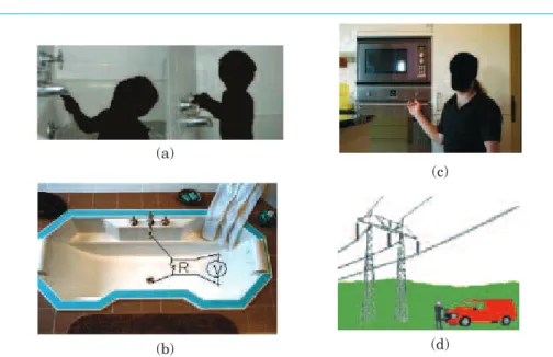
When a person simultaneously touches two conductive objects that are at dif-ferent potentials, a so-called contact current flows through his/her body. This is something very common though, most of the time, we do not even notice. Indeed the current is so weak that it is under the human level current percep-tion, near 0.5 mA (Hilert et al, 2002; Leitgeb, 1998, Fig. 7). For instance, when taking a shower or a bath (Fig. 8), you need to touch the faucet handle, the spout or the water stream. A voltage difference (50 Hz value) may appear between the object in contact (with one
(a) (b)
Fig. 6: External E-field (a) and B-field (b) effects on a human being and resul-tant internal currents and E-field due to current densities in the body. The large arrows over the head (a) indicate a significant increase of the external E-field (compared to the ambient field) due to peak effect (about 10 times higher).
Fig. 7: Distribution of the cumulative probability perception threshold cur-rent (Leitgeb, 2003)
hand for example) and your feet. As your body has an impedance close to 500-3000 Ω, just 100 mV difference, allows a current of 0.2 mA to flow through your body during the contact (depending on the source impedance). That current may flow through the body via the easiest paths, like the bone marrow which is a very good conductive material, particularly for children. That current creates local current densities and thus generates also internal E-field. Dawson et al., 2001 estimated that a 50 µA exposure produces about 650 mV/m in 5 % of the bone marrow (bone marrow conductivity not uniform) in the lower arm of an 18 kg child, 4-year old (more details in next section). The origin of the contact voltage is manifold. It may arise from either return current in the grounding system and/or as a result of Faraday induction in any circuit, including electrical cir-cuit, metallic circuit. The latter can be influenced by the proximity of power lines and even can propagate far away owing to particular metallic ducts and/or earthing networks in dense habitat.
With a contact current of 0.1 mA, the order of amplitudes of the E-field in the bone marrow (see later for further details) is several hundreds of mV/m for the arm and several tens of mV/m for the spinal backbone.
Contact currents can give rise to possibly hazardous internal field levels higher than the established safety threshold (ref: part 1.1) and seems thus to be the only potential source of biolo-gical effects. This contact current, which may induce relatively large internal E-field, cannot be detected by most of the population as its level is lower than the perception level, though, except for hypersensitive people. Furthermore, the occurrence of contact currents is relatively limited, but when they appear, that may happen for several hours every day, which is particularly delicate for foetus, babies or small children.
It must also be pointed out that there is no epidemiological evidence linking the risk of childhood leukemia and contact currents. Nevertheless, such epidemio-logical study would be particularly dif-ficult to be performed due to the com-plexity of the measurements involved.
Evaluation of internal E-field in the bone marrow for ELF fields and contact current cases
From 1996, many authors evaluated internal E-fields in different configura-tions (Barchanski et al, 2006; Struchly et al., 1996, 2005; Dawson et al., 1997, 1998, 2001, 2002, 2003; Dimbylov, 1998, 2000, 2005; Cech et al., 2007, 2008; Caputa et al., 2002; Jart et al., 1998). Currently, we are not aware of any measurements done inside the body of a living human, thus results are obtained by numerical simulations. Different human models can be found worldwide, from children to adults, and including even pregnant women. Available software allows accounting for detailed models of the whole body, with different electrical characteristics (e.g. conductivity, permeability) for the different tissues.
Finite difference and finite element models are mostly used. The 3-D model is discretized in so-called “voxels”, of about 3 mm size. Sources may be initial B-field, or E-field or both, or contact current between any parts of the body. The output of interest for our purpose is, namely, the internal E-field in the bone marrow.
The conductivity of the bone marrow (there are yellow and red marrows) changes with age. Most common values as stated by Reilly, 1998 vary between 0.05 S/m to 0.2 S/m (foetus).
Eventually, the calculated effects of E-field, B-field and contact currents may be summarized as follows:
1) as the “material” is considered as linear, everything is proportional to the value of the external fields. A double external field generates a double inter-nal field.
2) An E-field of 10 kV/m generates an internal E-field of about 30 mV/m in the bone marrow (adult).
3) A B-field of 100 µT gives rise to an internal E-field of 1 mV/m in the bone marrow (adult).
4) A contact current of 0.1 mA pro-duces an internal E-field up to 500 mV/m in the arm for adult and up to 1500 mV/m for foetus.
It must be pointed out that these values depend strongly on the condu-ctivity so that only an order of magni-tude has to be considered. Moreover, working power frequency is either 50 Hz or 60 Hz, but 20 % shift in either ways has no significance here.
Based on previous physical observa-tions, we may argue the following: (a)
(b)
(c)
(d)
Fig. 8: Examples of contact current at 50 Hz : (a) potential faucet to drain through the body contact current (b) faucet to drain contact voltage measurement (R = 1 kΩ), (c) touch voltage of metallic apparatus which may generate contact current, (d) contact voltage on a car placed in an ambient electric field, which may also generate contact current.
1) Concerning external E-field and/or B-field effects on bone marrow internal E-field:
– as WHO considers 10 mV/m as a basic minimum level able to potentially disturb biological mechanism (WHO, 2007, page 116, “…based on current evi-dence threshold values around 10-100 mV/m seem more likely”),
– as maximum E-field (just under a 400 kV line) is close to, and most gene-rally lower than, 10 kV/m,
– as maximum B-field (just under a 400 kV line) is close to 20 µT, then, there is no way to consider any more direct effects of E-field or B-field on any mechanism which could be the source of childhood leukemia.
Indeed, E-field in critical situations, i.e. close to a threshold value, is very much influenced inside home by the walls, metallic tubes or plates; there is no way to observe a value as high as 10 kV/m inside residential houses. It is just a few tens of V/m, what means 1000 times lower than the potential threshold. 2) Concerning contact currents effect on bone marrow internal E-field: – Contact currents may induce a signi-ficant internal E-field in the bone marrow and must be more deeply investigated.
Part 2: The contact current
hypothesis - A deeper
analysis
Origin of contact currents in residential homes
Definition of contact current
The contact current is a current flowing through the body that appears when two members of the body are in contact with two metallic parts subject to a different potential. It is thus linked to a potential difference called contact voltage. The contact current cannot be simply calculated as the ratio between the “open circuit” contact voltage and the body impedance. In fact, the whole elec-tric circuit behind the two contact points (Thevenin equivalent) has to be considered. Indeed, the voltage source behind the two contact points has an internal impedance which may be huge and in that case, no significant current would be generated.
Therefore, a suitable evaluation of such risk requires two measurements: (i) the open circuit voltage and (ii) the short-circuit current value. For practical rea-sons, the short-circuit measurement is replaced by the measurement of the voltage applied at a very high
resis-tance (in practice, the body impedance is taken in the range 0.5 to 3 kΩ) placed between the two contact areas (see Fig. 8b). In many cases, this second mea-surement gives a quasi-null value, which means that internal global impedance of the circuit is extremely large (several MΩ), thus with no conse-quences (too low contact current). The contact current is not related to the electrostatic discharges (ESD). The latter is a transient current (a few ns) due to charge equilibration between two “objects”. In this paper, this phenomenon is not taken into account. ESD is generally considered as no source of any long-term pathologic consequences, despite its very distu-rbing, but instantaneous effect.
Grounding systems in residential distribution circuit
Ground and neutral are closely related. Ground provides a low impedance path to earth to prevent the appearance of transient hazardous voltages. Normally, a grounding conductor does not carry current. Neutral is a circuit conductor that may carry current and which is usually connected to ground. The basic rule in a distribution circuit is that neutral is mostly isolated from ground. The neutral is often connected to the earth at the transformer or
sub-Table II: Different models found in the literature, sources and observed effects (50 Hz or 60 Hz)
Model External sources Effects
Dawson, 1997 voxel of 3.6 mm for E field ~20 mV/m in bone marrow
man of 76 kg, 1.77 m 10 to 20 kV/m (current density of 1 mA/m2)
Dawson, 1998 B-field 1 µT ~10 µV/m in bone marrow
Hart &Gandhi, E-field of 10 kV/m ~3 mV/m in spinal liquid
1998 B-field of 33 µT
Dawson, 2001 virtual child contact current of 0.1 mA up to 500 mV/m in arms
(18 kg, 1.1 m) up to 45 mV/m in spinal backbone marrow
Caputa, 2002 “Brooks man” B-field of 1 µT 0.02 to 0.29 mV/m in bone marrow (104 kg, 1.8 m)
Dimbylov, 2005 “Naomi” B-field of 1 mT 6 to 48 mV/m in bone marrow
(60 kg, 1.63 m)
E-field of 1 kV/m 3 to 56 mV/m in the bone marrow Cech, 2007 “SILVY” pregnant B-field of 100 µT 3 mV/m in the foetal bone marrow
and 2008 women 30 weeks (current density of 0.6 mA/m2)
(89 kg, 1.8 m)
E-field of 5 kV/m 20 mV/m in foetal bone marrow (current density of 3.3 mA/m2) Combination of both 20 mV/m in the foetal bone marrow
station which supplies the low voltage line.
Different systems are used to minimize the voltage difference between neutral and local ground. There are two main approaches: the TT system (widely spread in Europe and in particular in Belgium) and the TN system (common in USA). In the TT system, the neutral is connected to the earth at several points along its length, but it is NOT connected to the earth inside homes. In the TN system, the neutral is connected to the earth inside home. Every time the neutral conductor is earthed, the neutral current can divert out of the line into the earth itself (through e.g. water pipes) and return to the transformer via a different path (closing the circuit). Any diverting cur-rent out of the neutral, inside home, is susceptible of generating potential contact currents, as they give rise to contact voltage at any location
(particu-larly on water arrival, radiator, earth plug…).
Another source is linked to faulty house wiring or faulty appliance. This case occurs roughly in 20 % of the homes and provokes an unintended phase con-nection to the earth. In a TT network, too large diverting current from phase to earth will force the differential pro-tection to open the circuit, this last being generally tuned at 30 mA on water rooms and about 300 mA at the origin of the electrical installation. So contact current up to either 30 mA or 300 mA can flow freely without any action of the protection. This allows fault current to divert out of the line. This current limit has been imposed by regulation, taking into account safety aspects linked to potential heart hazard. Establishing a lower limit is not possible as most installations have some diverting current and such a
reduction of the differential protection would cause frequent circuit interrup-tions every day.
Origin of contact current
The contact current sources may either come from external source (like B-field and E-field induced by power lines, cables, transformers…, Fig. 10(a)) or internal source (treated later on) (Fig. 10(b)).
In Fig. 10 (a), the feeder includes neu-tral and active wire going to distribu-tion box inside home. This box has a dedicated earth bar linked to the local earth (through earth switch (or breaker) for measurement purposes). All domestic circuits are then distributed to any local load from there by a feeder of three conductors, including one (green and yellow in Belgium) conductor which is the protective conductor (PE).
(a) (b)
Fig. 9: (a) Typical residential ground loop, earth isolator, earth bar, water and gas ducts links, and earth distribution in TT schema. With example of one phase and three phase loads. (b) Typical earthing
(a) (b)
Fig. 10: (a) Typical model to evaluate induced voltages and currents in homes near power lines (b) US typical TN-S residential connection, including water pipe links. Inet loadis the net current load coming “back” from the load in the “neutral” conductor (active conductor not drawn).
The local earth may be (as shown on the Fig. 9) a local closed loop around the house installed during the construction phase. In older houses, local earth is replaced by 2 m long rods in the garden. Water and gas arrivals are also repre-sented and must be connected to local earth by equipotential bonding. As water or gas arrivals are corrosion pro-tected in the ground, their earth resis-tance is relatively high (bad contact with earth) and the local earth link with a good electrical network earthing is needed to impose equipotentiality between most of the metallic circuits at home. Some of these last recommenda-tions (imposed by the law since 1981 in Belgium) may be missing or of bad quality.
A contact voltage may then appear, typi-cally between faucet and water evacua-tion. Depending on the material used for ducts, bathtub, heating system..., the internal impedance of the global circuit seen from the two contact points may be low enough to allow significant contact currents to flow through the body.
In Fig. 10 (b), typical for TN system, the net load current (resulting from any load inside home) coming back to the distribution feeder may divert at the panel where the local earth is linked to the neutral. As water pipes are also linked to the earth, any load current (not only faulty ones as for the TT scheme) may partially divert to the earth and water pipes, creating thus systematic contact voltage.
In both cases, the proximity of power lines (as shown on Fig. 10 (a)) may
induce a voltage in any existing circuit, including earthing and any metallic ducts. That voltage has to be superim-posed to the further explained case. Obviously, the induced voltage in the circuit loops depends on their size and orientation with regard to the power line B-field.
This may be a potential link between the B-field and possible effects on human.
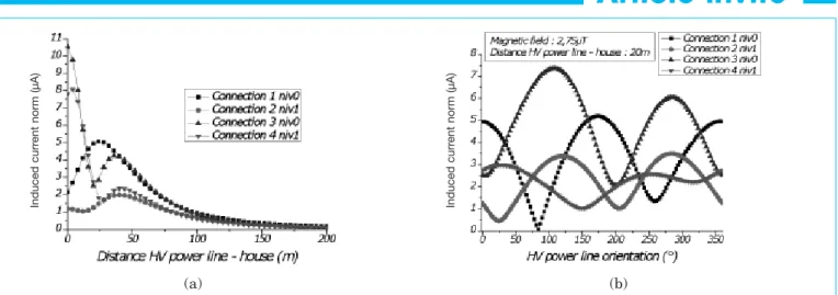
The part of the contact voltage (and contact current) due to power lines may be quantified by numerical simulation. Fig. 11 shows such evaluation. A limited 10 µA contact current has been observed in the most critical cases (large loop well oriented, coupled with strong B-field).
Most significant contact currents (larger than a few tens of µA) are thus due to bad installations. This will be confirmed later on by the absence of correlation between B-field and contact currents, as recently evidenced in a 90-homes measurement campaing in Belgium (Fig. 13). Further measure-ments are still performed to improve the data base size and are under inves-tigation.
Fig. 8 a, c and d as well as Fig. 10 b represent typical every day activity with potential contact currents. Following remarks concerning contact currents may finally be detailed: 1) In a TT scheme, typical in Belgium, the return current from any
unba-lanced or single phase circuit is going back to the transformer via the neutral conductor (and thus not via the earth). 2) In a TN scheme, typical in USA, the return current from any circuit is par-tially going back to the transformer through the local earth and partially through the neutral or PEN wire. 3) In a TT scheme, there is, theoreti-cally, no current in the local ground for compliant installations. However, loss of insulation in some circuit or in elec-trical appliance (fault) may allow part of the load to go through the earth link, if any. As earth resistance is in the range of 6 to 30 Ω (earth of the exposed-conductive-parts), a 1 mA loss of cur-rent will impose a global 30 mV on all earth rods in every socket. In an IT scheme, the earth return path for diverted currents, to the transformer is obviously more impedant and these currents will be limited in amplitude. 4) There are rules of installations which force all metallic tubes (water feed, gaz, domestic hot water heating installation...) to be linked to the earth switch (or breaker). This last is very often missing in installations older than 1981 (Belgium).
5) If no earth link exists for some loads (e.g. washing machines, hair dryer), the partial loss of insulation on active cir-cuit will give rise to some voltage on the machine metallic parts.
6) In the three last cases, a voltage exists on some metallic parts and, when a human being touches it, a new return path for the current appears: through the body impedance and impedance from the feet to the earth and finally back to the transformer. The body con-tact resistance to ground is very small in case of nude humid feet, as may be
(a) (b)
Fig. 11: Induced contact current in conductive loops in a house in function of the 400 kV HV power line (a) distance and (b) orientation.
In d u c e d c u rr e n t n o rm (µ A ) In d u c e d c u rr e n t n o rm (µ A )
the case in bathrooms, the corresponding contact current may be quite high; yet no protection would open any circuit below a certain level.
7) In a TN scheme, even if the installa-tion complies with the regulainstalla-tion, the earth arrival at each socket is poten-tiated, which clearly favours contact currents.
8) Human being impedance is in the range of 0.5 to 3 kΩ (voltage dependent). If there are no other impedance in series, a contact voltage of 50 mV is enough to obtain a 0.1 mA contact current. 9) The most obvious sources of contact current are (i) the faucet to the drain in shower and bath, which would limit body impedance to its minimum near 500 Ω and (ii) contact with machines or radiator to the feet on a wet surface. 10) Sources of contact current exist also in the environment of power lines, for example, when touching a pylon or a car. Voltage difference occurs between these large metallic objects and the feet. But these situations are rare and cannot be considered as long-term exposure.
Belgian residential homes: level and protection
Contact current in Belgium private homes
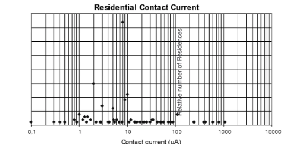
Fig. 12 shows the authors’ recent overview on 90 randomly chosen houses in Belgium. The mean level of contact current is limited to tens of µA. But several hundreds of µA have been detected in some of these houses. Only 6 houses out of the 90 considered have contact currents higher than 100 µA.
Potential correlation between contact currents and external B-field
The measured contact currents and internal B-field in the Belgian residen-tial homes is observed in Fig. 13. Up to now and from the authors’ study, no correlation has been observed in Belgium between the contact current level and the B-field.
Global overview of current electrical installation protections in Belgium
In Belgium (governmental statistics by FPS Economy, DG Energy), there are about 4 million residences (either house or apartment). They can be classified as: – type 1: 1.7 million very old-fashioned (before 1945);
– type 2: 1.5 million old-fashioned resi-dences (1945 to 1981);
– type 3: 800.000 residence post-1981 (year when national RGIE regulations appeared).
The experience of an authorized company10 shows that, about 50 % of Type 1 residences have no earthing. Most of the rest have at least one kind of earthing, but only 50 % of them have a differential at 300 mA at the origin of the installation.
Belgian residential park has mainly a TT scheme. But in some large areas (Bruxelles, Charleroi), there are still installations with an IT scheme (WEB.12).
It is known by certification utilities that Belgium park of residential houses and apartments have about 40% of bad earthing, but only part of it may be sub-ject to relatively large contact currents. This is most probably due to the non-conductive tubes used more and more in the installations.
In modern installations, conductive tubes for water and gas have disap-peared. In older installations, such con-ducts are progressively substituted. Therefore, most of the described problems will be clearly reduced in the coming years.
Part 3: Key actions to
undertake
Let first summarize the facts:
1) The values of external E- or B-field are never high enough to induce a cor-Fig. 12: Contact current level in residential park in Belgium (90 homes),
authors’ study.
Fig. 13: Ninety homes authors’ study in Belgium. Maximum contact current versus median B-field measured in each home.
10 Personal communication by SGS (Guy Lourtie). SGS Statutory Services Belgium ASBL/VZW
Business Riverside Park, Boulevard International, 55/D, B1070 Bruxelles -Belgium R e la ti v e n u m b e r o f R e s id e n c e s C o n ta c t c u rr e n t in th e b a th ro o m (µ A )
responding internal E-field in the body (direct effect) higher than the biological threshold limit fixed from 10 mV/m to 100 mV/m (WHO, 2007, p116) for ELF fields (50 Hz).
2) Some houses of the Belgian residen-tial park may have significant, yet non perceptible, contact currents, which may induce internal E-field in the bone marrow over the threshold. The time of exposure is limited, though.
3) Contact currents may appear either from ageing and/or bad installations and/or from the proximity of power lines and other large load installations. 4) There is currently no scientific evi-dence of any adverse health effect of ELF fields but a potential actor may be linked to a significant contact current. Based on former observations and analyses, we should apply the so-called “precautionary principle” (PP) based on epidemiological observations, with potential correlation to health effect, based on the sole ambient B-field ? What can be advised to avoid contact currents ?
Precautionary principle (PP)
European Commission policy has emphatically stated that application of the PP has to be based on (1) a careful analysis of the scientific literature, (2) an identified hazard, and (3) it cannot be used for risks that are speculative or not established by scientific evidence. PP must not be confounded with the zero risk.
WHO has been developing a Precautio-nary Framework which establishes both general principles for applying the PP, and specific guidance on its particu-larization to ELF fields. The latest draft Framework was released in October 2004. The key conclusions are:
“Under the WHO Precautionary Frame-work, childhood leukaemia warrants a thorough consideration of precaution-ary measures including detailed cost-benefit or cost-effectiveness analyses” and “…even after fully allowing for the legitimate desire by society to err on the safe side, it seems likely that only very low-cost measures will be justified.”
Both industry and government would benefit by improved practices in risk
communication. In the absence of fore-seeable health benefit, “precautionary” measures are both scientifically unjus-tified and legally problematic (WHO, Web.9; Foster et al, 2000).
Keeping this in mind, what kind of actions could be undertaken?
Solving the problem of contact currents
It is relatively easy and of extremely low cost to limit contact currents to insignificant values.
Residential park in countries like Belgium (with either a TT or IT system for distribution network), must all have a link between earthing of the electrical installation and metallic circuits like water and gas conducts. This is a sim-ple, no/low cost measure that is imposed to new installations (since 1981) but rarely fulfilled in old installa-tions. Houses where plastic tubes are used for water and gas do not need such links.
Obviously a compliant installation, including earthing is imperative as well as differential protection. Certification companies can help to verify the instal-lation efficiency and conformity. Particular situations (appartment located above or in the vicinity of a sub-station) may find local ways of protec-tion (such as B-field screens) to limit contact current by induction into circuit loops.
For those particularly sensitive to EM fields and for houses with no self pro-tection (no metallic parts in the struc-ture), in-house E-field in situation just next to 400 kV power lines, may easily be reduced. The installation of a simple very thin sheet of metallic material on their roof (inside) would annihilate external effects on their in-house E-field and limit it to the in-house generated field. The modern anti-lightning roof protection (a rough meshed network on the whole roof, linked to the ground), if any, may also serve to that aim.
Conclusions
Exposure to external ELF electric and magnetic fields induces electric fields inside the body.
As mechanisms become only plausible with fields above certain strength, in agreement with NIEHS, we just fix a minimum of several tens of mV/m of internal electric field inside bone mar-row. This level is required to be able to discriminate from inherent random noise.
In Europe, such a level of internal E-field cannot be due to direct effect of any ambient ELF magnetic or electric field generated by high power lines or cables.
Such a level of field can however be pro-voked by particular contact currents that depend on the local electrical installation.
Simple modifications of these installa-tions may easily help to limit and/or avoid contact current level in any resi-dence.
Following WHO recommendations, it is thus strongly advised:
– To enforce wiring regulations to reduce unintentional ground current, while ensuring safety.
– To do more research to assess the capa-bility of residential electrical grounding and plumbing practices to give rise to contact currents in residences.
– To adopt low cost precautionary mea-sures to reduce exposure and do not compromise the health, social and eco-nomic benefits of electricity.
There is a considerable potential to reduce fields without loss of perfor-mance of many electric appliances in every day life, which has to be recom-mended.
Last but not least, large epidemiologic studies pointing out a possible moderate increase of the risk (factor 2) for ALL in small children, being based on external B-field higher than 0.4 µT, have few chances to have had looked at the appropriate data (external B-field) as that data is, for sure, a negligible direct effect for potential adverse health effects. It must nevertheless be admit-ted that there are no other clear data to easily look at.
The replica of the conclusions by different studies is nevertheless disturbing. It suggests that indirect links, like con-tact current could be a hypothesis to
take into account. That may be consis-tent with some domestic distribution rules in some countries. But in a situa-tion like in Belgium, a fortiori with pro-posed changes in the give rise to instal-lations, there will be no way to find any effect, direct or indirect, due to the B-field.
This paper, based on both a literature survey and authors’ own measure-ments, seems to orientate research in another direction, first suggested by Kavet et al: everybody should have his/her installation verified and modi-fied to ensure conformity, if necessary before looking for an external source of the problem. However, manufacturers and power line owners should also care-fully study how to reduce ambient fields at any frequency.
References
Ahlbom, A., Cardis E., Green, A., et al, ICNIRP Standing Committee on Epidemiology, 2001. Review of the epidemio-logic literature on EMF and health. Environmental Health Perspectives, Vol. 109, pp. 911-933.
Ahlbom, A., Day, N., Feychting, M. et al, 2000. A pooled analysis of magnetic fields and childhood leukaemia. British Journal of Cancer, Vol. 83, pp. 692-698.
Barchanski A., M. Clemens, H. De Gersem, Thomas Weiland, 2006. Efficient calculation of current densities in the human body induced by arbitrarily shaped low-frequency magnetic field sources. Journal of Computational Physics, Vol. 214, pp. 81-95. Bertil Hille. Ion Channels of Excitable Membranes. Third Edition. 2001. Sinauer Associates, Sunderland Massachusetts USA. Bowman J., Niple J., Kavet R., 2006. Pilot Measurement of ELF Contact Currents in Some Electric Utility Occupations. Journal of Occupational and Environmental Hygiene, Vol. 3, pp. 323-333.
Brain J.D., Kavet R., McCormick D.L. et al, 2003. Workshop Summary: Childhood leukemia: electric and magnetic fields as pos-sible risk factors. Journal of Environmental Health Perspectives, Vol. 111, pp. 962-970. Brewer A.K., Passwater R., 1976. Physics of the cell membrane. Mechanisms involved in cancer. American Clinical Lab, Vol. 10, pp. 37-45.
Brix J. et al, 2001. Measurement of the individual exposure to 50 and 16 2/3 Hz magnetic fields within the bavarian popula-tion. Bioelectromagnetics, Vol. 22, N 5, pp. 323-332.
Caputa K., Dimbylow P. J., Dawson T. W. and
Stuchly M. A., 2002. Modelling fields induced in humans by 50/60Hz magnetic fields: reliability of the results and effects of model variations. Physics in Medicine and Biology, Vol. 47, pp. 1391-1398.
Cech R., Leitgeb N. and Pediaditis M., 2007. Foetal exposure to low frequency electric and magnetic fields. Physics in Medicine and Biology, Vol. 52, pp. 879-888.
Cech R., Leitgeb N. and Pediaditis M., 2008. Current densities in a pregnant woman model induced by simultaneous ELF electric and magnetic field exposure. Physics in Medicine and Biology, Vol. 53, pp. 177-186.
Chiu S., Stuchly M.A., 2005. Electric Fields in Bone Marrow Substructures at Power-Lines Frequencies. IEEE Transactions on Biomedical Engineering, Vol. 52, N 6, pp. 1103-1109.
Cone C.D., 1975. The role of surface electri-cal transmembrane potential in normal and malignant mitogenesis. Annals of the New York Academy of Sciences, Vol. 238, pp 420-35.
Cone C.D., 1985. Transmembrane Potentials and Characteristics of Immune and Tumor Cells. Boca Raton, Florida: CRC Press. Cope F.W., 1978. A medical application of the Ling Association-Induction Hypothesis: The high potassium, low sodium diet of the Gerson cancer therapy. Physiological Chemistry and Physics, Vol. 10, N 5, pp. 465-468.
Dawson T. W., Caputa K. and Stuchly M. A., 1997. A comparison of 60Hz uniform magnetic and electric induction in the human body. Physics in Medicine and Biology, Vol. 42, pp. 2319-2329.
Dawson T. W., 1998. High-Resolution Organ Dosimetry for Human Exposure to low-fre-quency Magnetic fields. IEEE Transactions on Magnetics, Vol. 34, N 3, pp. 708-718. Dawson T. W., Caputa K., Stuchly M. A. and Kavet R., 2001. Electric fields in the human body resulting from 60Hz contact currents. IEEE Transactions on Biomedical Engineering, Vol. 48, N 9, pp. 1020-1026. Dawson T. W., Caputa K., Stuchly M. A. and Kavet R., 2002. Pacemaker Interface by 60 Hz Contact Currents. IEEE Transactions on Biomedical Engineering, Vol. 49, N 8, pp. 878-886.
Dawson T. W., Caputa K., Stuchly M. A. and Kavet R., 2003. Comparison of Electric fields induced in humans and Rodents by 60 Hz Contact Currents. IEEE Transactions on Biomedical Engineering, Vol. 50, N 6, pp. 744-753.
Decat G., Van den Heuvel I., Mulpas L., 2005. Monitoring survey of the 50 Hz magne-tic field for the estimation of the proportion of Belgian children exposed to the epidemio-logical cut-off points of 0.2, 0.3 and 0.4 micro tesla. Erembodegem, Flemish Environmental Agency.
Dickinson H.O., 2005. The causes of child-hood leukaemia: delayed exposure to infec-tion may trigger leukaemia after prenatal damage to DNA. British Medical Journal, Vol. 330, pp. 1279-1280
Dimbylow P.J., 1998. Induced current densi-ties from low-frequency magnetic fields in a 2mm resolution, anatomically model of the body. Physics in Medicine and Biology, Vol. 43, pp. 221-230.
Dimbylow P.J., 2000. Current in a 2mm reso-lution anatomically realistic model of the body induced by low frequency electric fields. Physics in Medicine and Biology, Vol. 45, pp.1013-1022.
Dimbylow P.J., 2005. Development of the female voxel phantom, NAOMI, and its appli-cation to calculations of induced current den-sities and electric fields from applied low fre-quency magnetic and electric fields. Physics in Medicine and Biology, Vol. 50, pp. 1047-1070.
Foliart D.E., Iriye R.I., Tarr K.J. et al, 2001. Alternative magnetic field exposure metrics: Relationship to TWA, appliance use, and demographic characteristics of children in a leukemia survival study. Bioelectromagnetics, Vol. 22, pp. 574–580.
Foster K.R., Vecchia P., Repacholi M.H., 2000. Science and the precautionary princi-ple. Science 288, pp. 979-980.
Hart R.A. and Gandhi Om P., 1998. Comparison of cardiac-induced endogenous fields and power frequency induced exoge-nous fields in an anatomical model of the human body. Physics in Medicine and Biology, Vol. 43, pp. 3083-3099.
Hazelwood C.K., Chang D.C., Nichold B.J., Woesner D.E., 1974. Nuclear magnetic reso-nance transverse relaxation times of water protons in skeletal muscle. Biophysical Journal, Vol. 14, pp. 583-606.
Hillert L., Berglind N., Arnetz B.B., Bellander T., 2002. Prevalence of self-reported hypersensitivity to electric or magnetic field in a population based questionnary survey. Scandinavian Journal of Work Environment and Health, Vol. 28, pp. 33-41.
Greenland S., Sheppard A.R., Kaune W.T. et al, 2000. A pooled analysis of magnetic fields wire codes, and childhood leukemia. Epidemiology, Vol. 11, pp. 624–634. Hoeffelman J., Decat G., Lilien J.L., 2004. Assessment of the Electric and Magnetic field levels in the vicinity of the HV overhead power lines in Belgium. Paris, CIGRE ses-sion papers, Group C3 (8 pages).
Kaune W.T., Zafanella L.E., 1994. Assessing historical exposures of children to power-fre-quency magnetic field. Journal of Exposure Analysis and Environmental Epidemiology, Vol. 4, pp. 149-170.
Kaune W.T. et al, 1994. Development of a protocol for assessing time-weighted average exposures of young children to