HAL Id: hal-01118958
https://hal.archives-ouvertes.fr/hal-01118958
Submitted on 20 Feb 2015
HAL is a multi-disciplinary open access
archive for the deposit and dissemination of
sci-entific research documents, whether they are
pub-lished or not. The documents may come from
teaching and research institutions in France or
abroad, or from public or private research centers.
L’archive ouverte pluridisciplinaire HAL, est
destinée au dépôt et à la diffusion de documents
scientifiques de niveau recherche, publiés ou non,
émanant des établissements d’enseignement et de
recherche français ou étrangers, des laboratoires
publics ou privés.
A Scalable Cloud Storage for Sensor Networks
Gérôme Bovet, Gautier Briard, Jean Hennebert
To cite this version:
Gérôme Bovet, Gautier Briard, Jean Hennebert. A Scalable Cloud Storage for Sensor Networks.
Fifth International Workshop on the Web of Things (WoT 2014), Oct 2014, Boston, United States.
�hal-01118958�
A Scalable Cloud Storage for Sensor Networks
Gérôme Bovet
Laboratory for Communication and Processing of Information Telecom ParisTech
Paris, France
[email protected]
Gautier Briard
Department of Computer Science University of Belfort-Montbéliard
Belfort, France
[email protected]
Jean Hennebert
Institute of Complex Systems
University of Applied Sciences Western Switzerland Fribourg, Switzerland
[email protected]
ABSTRACT
Data storage has become a major topic in sensor networks as large quantities of data need to be archived for future processing. In this paper, we present a cloud storage solu-tion benefiting from the available memory on smart things becoming data nodes. In-network storage reduces the heavy traffic resulting of the transmission of all the data to an outside central sink. The system built on agents allows an autonomous management of the cloud and therefore requires no human in the loop. It also makes an intensive use of Web technologies to follow the clear trend of sensors adopting the Web-of-Things paradigm. Further, we make a performance evaluation demonstrating its suitability in building manage-ment systems.
Categories and Subject Descriptors
H.2.4 [Information Systems]: Distributed databases
General Terms
Design
Keywords
Cloud storage, Web-of-Things, Sensor networks
1.
INTRODUCTION
Since a few years, Web technologies are gaining more im-portance for communication between so-called things. Fol-lowing this direction, the Web-of-Things (WoT) paradigm has emerged with, as central vision, a common application layer targeting a seamless integration of heterogeneous de-vices [5]. The strengths of this approach is to rely on well accepted protocols and patterns such as HTTP and Repre-sentational State Transfer (REST) services, providing high
Permission to make digital or hard copies of all or part of this work for personal or classroom use is granted without fee provided that copies are not made or distributed for profit or commercial advantage and that copies bear this notice and the full citation on the first page. To copy otherwise, to republish, to post on servers or to redistribute to lists, requires prior specific permission and/or a fee.
WoT ’14October 08 2014, Cambridge, MA, USA.
Copyright 2014 ACM 978-1-4503-3066-4/14/10 ...$15.00.
scalability while decoupling applications from software and hardware concerns.
We can nowadays find many of such smart things, for ex-ample sensors in buildings or daily-life objects in our homes. Smart environment applications are also emerging, aiming at increasing the user experience (or more generally the com-fort) while optimising the energy consumption. Having ac-cess to historical data of sensors is often required by those applications. The field of smart buildings is a compelling example where control loops, or data-driven techniques tar-geting an intelligent adaptation of the building according to the users behaviour make an intensive use of historical data [9]. Current approaches are deporting the storage out-side of the sensor network in a single database or using a commercial cloud service. Although being viable solutions, they involve a series of constraints which are often not ac-ceptable for building owners. The first worry is about the privacy of sensitive data such as presence sensor or electric consumption data. Secondly, forwarding the data outside the sensor network implies a gateway that is susceptible to be overloaded by the traffic and that represents a single point of failure as well as a point of entry for attacks. Consider-ing those problematics, it appears that the best solution for owners would be to disconnect the sensor network from the rest of the world, thus increasing security while ensuring pri-vacy by storing historical data within the sensor network.
In this paper, we present a mechanism for distributing his-torical sensor data on things, forming an in-network cloud relying on Web technologies. Our system distinguishes it-self from others by being fully autonomous and requiring no human in the loop. We put special attention on limiting the network traffic while ensuring maximum fail safety and scalability.
2.
RELATED WORK
Accessing data sources over RESTful APIs has made its way into databases especially built for storing time series. InfluxDB [1] is an open-source distributed databases making use of Web technologies such as HTTP, JSON and JavaScript for writing and reading data of sensors. Although it states itself as distributed and horizontally scalable, the documen-tation section describing the clustering is currently empty. StormDB [3] offers a cloud-based out of the box storage for time series. It bases on the Postgres-XC project for
dis-tributing data across multiple Postgres databases. A load balancer dispatches requests to coordinators who are respon-sible for distributing those requests to data nodes. They are also responsible during read queries for merging the data coming from multiple data nodes. These freely available so-lutions only run on common operating systems as Linux, Mac and Windows. In addition, their core engines require a certain amount of resources (CPU and memory) that are not available on smart things. Applications using StormDB were indeed developed successfully for smart city context but relying on a remote cloud based implementation [4].
When considering a distributed in-network storage, the placement of the data nodes is determinant when trying to minimize the total energy for gathering data to the storage nodes and replying queries. Several algorithms optimizing the placement of the data nodes are proposed in [11]. All of them are using trees as model structure for representing the problem. Trees are categorized as fixed or dynamic, depend-ing on the problem’s nature. Those algorithms, especially for dynamic trees are relevant to our problematic as devices can appear and disappear in a building.
The idea of storing historical data directly on sensor de-vices is not a new topic. This was studied for example in [7] where constrained devices used in sensor networks are con-sidered for local storage. They developed Capsule, a rich, flexible and portable object storage abstraction that offers stream, file, array, queue and index storage objects for data storage and retrieval.
3.
AIM AND ARCHITECTURE
We are proposing here an architecture, processes and in-terfaces supporting storage capacity on the already available devices in the sensor network, like sensors and gateways. With the advances made in electronics in recent times, sen-sors embed a non-negligible amount of memory that is often underused. This is even more the case for gateways hav-ing storage capacities of several mega- or even gigabytes. All this memory can therefore be used for storing historical data on Storage Peers (SP) that will be managed by Storage Coordinators (SC). We also propose to include the following features:
Location based grouping SP are placed among the net-work where data is produced to avoid traffic propaga-tion over the whole network. This also ensures that a failure in a specific part of the building will not affect the rest of it. We hereby base our grouping according to the logical room structure of the building.
Replication for prevention An active agent takes actions for ensuring that data are replicated at least once on the SPs. Every SC is also backed up by a second one. Energy efficient retrieval The SC includes an algorithm based on the data repartition table to select the ap-propriate SP for limiting exchange of values.
Decoupling with network-layer The solution is decou-pled from the network topology and routing protocol, able to work with IPv4 addresses as well with IPv6. On-demand storage Storage resources are dynamically
an-nounced for saving storage space.
Efficient application layer CoAP (Constrained Applica-tion Protocol) [10] is used as applicaApplica-tion-layer proto-col for accessing RESTful APIs. CoAP is lighter than HTTP and contributes to the efficiency of the system. The observe option [6] is used for implementing noti-fications between sensors and the storage peers. Multicast based Multicast is used for efficient
communi-cation with several peers at one time in combination with the CoAP protocol.
3.1
Architecture
We propose an architecture based on the structural rooms and floors composition of a building. The logical structure of a building forms a tree where agents and producers are disposed. We extend this perception of a building by intro-ducing the concept of zones grouping contiguous parts of a building, as illustrated in Figure 1. Each zone is managed by two SCs, one master and one backup, having their knowl-edge limited to their own content and to the references to their parent and children zones. This allows to split a build-ing into autonomous regions that are not affected by failures in other zones. In addition, it avoids that each coordinator knows the whole structure of the building, therefore reduc-ing the amount of synchronization data. Zones are formed dynamically during the operation according to the producers and the peers repartition. The principle of zone management is detailed in section 4. !" !" !" !" # !# !# # # !# !# # # !# !# # !# !# # !# # !# # # !""#$%&"'()*"' *&+,-!(.$%/""!01%/""!2 !""#$%/""!2)&"'()*"' *&+,-!(.$%3 !""#$%/""!0)&"'()*"' *&+,-!(.$%,+4+.5 !""#$%,+4+.5)/""!0)&"'()*"' *&+,-!(.$%3
Figure 1: In-network cloud storage architecture
based on building zones.
3.2
Entities and Roles
Our solution is composed of several agents having differ-ent behaviours depending mainly on their memory capacity. The agent applications are loaded in the device during de-ployment. Powerful devices may run multiple agents.
3.2.1
Storage Peers
Storage peers (SPs) manage the access to historical data according to the available local memory. They announce their capacity at startup to the Storage Coordinator (SC) managing the zone they reside in, indicating they are ready to receive data from producers. The storage management type used on the peer is hidden by a RESTful API providing functions for creating new datasets, adding entries as well as
reading historical data. This approach allows for decoupling the storage from database technologies and exposes a single common storage interface for all peers. SCs and producers have no clue about which technology is used for the internal storage, as this could be for example MySQL, SQLite, flat files or even only EEPROM storage with specific indexing on constrained devices, for example using Capsule [7]. SPs regularly announce their storage capacity to the SC agent responsible for their location in the building.
3.2.2
Storage Coordinators
SCs manage the composition of the zones as well as the repartition of data between the peers. It starts up by look-ing after another coordinator already managlook-ing the location it resides in. If there is already a SC, it will put itself in stand-by, waiting to get promoted as backup. If no answer is received, it will promote itself as master coordinator for its location. It then periodically communicates with its par-ent and children in order to take decisions about merging or splitting zones. A major task of the storage coordinator is to manage the repartition of data between SPs by ensuring that each tuple of data is duplicated at least once. Finally, it serves as entry point for retrieval requests and will use its internal repartition table to find out which peers are con-cerned by the query.
3.2.3
Producer
A producer can be a sensor, a daily life object or any kind of thing that produces data in the form of notifications. The observer pattern of CoAP is here used among with multicast as notification mechanism for transmitting new values to storage peers in a single packet.
3.2.4
Client
The client stands for humans or applications requiring storage of historical data of a particular resource. Before a resource gets stored, an announcement by a client has to be sent to the storage coordinator responsible for the zone where the resource resides. Clients will afterwards be able to send read requests to the storage coordinator by indicating a resource and an interval of time for filtering purpose.
3.3
Interfaces
We define three types of interfaces that are used in our solution. Each one is accessible over a RESTful API and targets specific functionalities.
General management interface: SCs implement the server side of this multicast interface used for discovery pur-pose. Each participant of the cloud will use this interface to send a GET request for seeking after a SC managing a zone. For example, a client looking for the SC manag-ing resources in the kitchen will send the followmanag-ing request:
coap://229.0.5.32/home/floor1/kitchen. Each storage
coordinator within the building will check if this location resides within their authority zone. Only the one that is managing this location will respond with the multicast ad-dress of its zone interface.
Zone interface: A specific zone interface is attributed to every zone, which is a unique multicast address generated during the zone creation. The purpose of this interface is for synchronization needs between the master coordinator with its backup, as well for the peers for communicating their fill-ing ratio. In addition, this interface is used by the
produc-ers for notifying peproduc-ers with new values. We avoided CoAP groupcom [8] because of constrained devices being unable to have multiple multicast addresses due to IP stack limita-tions. Clients send GET requests to this interface for retriev-ing historical data, as illustrated in the followretriev-ing request: coap://233.56.175.90/home/floor1/kitchen/temp?from= 2014-02-13&to=2014-02-18. Finally inter-zone synchroniza-tion is also achieved by using this interface.
Server interface: Each SC and SP has a server inter-face bound with its unicast address. For SCs, this interinter-face allows to manage their participation in the observation of resources by giving the observe token. This interface also offers the possibility to retrieve the history of a resource stored on the peer by specifying an interval. The promotion of backup SCs is also managed using this interface.
The decomposition into several interfaces is an interest-ing approach, especially combined with multicast. First, having one interface for each behavior and particularly for each zone concentrates the communication within the spe-cific zone without disturbing other zones or agents. Using multicast allows impersonal communications between par-ticipants. This impersonality improves the dynamics and fault tolerance of the solution as participants do not know the exact identity of their partners. We can illustrate this principle by citing the zone interface. SPs regularly notify their coordinator about remaining storage space. As this is achieved with multicast, they do not address a specific agent. This means that the agent can change over time without any consequence for the peers. For example if the master SC fails, peers will continue talking with the backup that will promote itself as master.
4.
ZONE COMPOSITION STRATEGIES
As previously mentioned, our cloud storage is split into several zones forming a tree. Each zone is authoritative for one or many contiguous locations of the building. The loca-tion grouping process can be seen under several perspectives, and many algorithms can be imagined for defining zones. However, as our aim is also to build an energy efficient solu-tion, we opted for an approach limiting the traffic between all the agents. SCs face two types of decisions during the grouping process: should they split their own zone into two new ones, and should they regroup a child zone with their current zone. Decisions are taken according to notions of costs.
4.1
Splitting
The coordinator for a zone Z will first compute the cost
C(Z1, Z2) for each possible decomposition into two new zones
Z1and Z2 according to Eq. (1). We limit this computation
to zones having at least two SCs and two SPs, and having obviously enough space for storing the historical data of re-sources residing within the zone. Finally, the minimum cost value among the possible decomposition is compared to the
individual cost Ci(Z) of the zone Z. The zone will be split if
the evaluation of Eq. 2 is true, i.e. if the best decomposition (minimising the cost) brings a gain of efficiency as compared to the current situation.
C(Z1, Z2) = Ci(Z1) + Ci(Z2) + Ce(Z1, Z2) (1)
Ci(Z) − min(C(Z1, Z2)) > ǫs (2)
storage peers within the zone. We consider that for-warding notifications to distant storage nodes is penal-izing.
Ce Inter-zone costs depending on the filling rate of the child
zone. Children zones are regularly sending some status data to their parent zone, which generates traffic. This traffic essentially depends on the filling rate of the child zone, as more messages will be exchanged as storage space decreases.
ǫs A cost gain factor above which the splitting is performed.
4.2
Merging
A SC can decide to merge its own zone with a child one in two situations:
Space: When one of the zones becomes full and has no more storage capacity. Grouping the zones will allow to increase the storage capacity and to postpone storage satu-ration.
Efficiency: When the cost of a single zone would be less than the actual situation. However, a SC has no knowledge about the internal structure (locations, storage peers and producers) of a child zone. This results in the incapacity of computing the costs for the merged zone. We opted for a solution where we compute an estimation of the cost Cp(Z) for the merged zone depending on each zone’s costs and internal location tree depth, as described in Eq. (3). The merging is performed if the evaluation of Eq. (4) is true, i.e. if the merging brings a gain.
Cp(Z) = (Ci(Z1) + Ci(Z2)) ∗ ln(D(Z1) + D(Z2)) (3)
C(Z1, Z2) − Cp(Z) > ǫm (4)
C(Z1, Z2) Two-zone cost computed as above.
D Depth of the zone’s internal location tree. Each zone is
composed of one or more contiguous locations repre-sented as a tree. The depth of the tree influences the probability of having distant producers and consumers.
ǫm A cost gain factor above which the merging is performed.
5.
PROTOCOL DETAILS
In this section we detail some behaviours of our proposed cloud storage for things. We assume that zones are already built and that the client has performed the SC discovery.
5.1
Data Announcement
We here describe the process of announcement and the internal communications as illustrated in Figure 2 part (a). The first step for a client is to announce its intention of stor-ing data for a particular resource and for a given amount of time. This is realized by sending a multicast packet con-taining the necessary information to the SC. In order to offer a lightweight and robust mechanism for the announce-ment, we decided to specify the interchange format with a JSON schema, visible in Listing 1. JSON schemas [2] are the equivalent to XML schemas and are used for validating data interchanged with Web services. As we are working in a world of constrained devices, using JSON appeared a reasonable choice.
Listing 1: JSON Schema for data storage announce-ment { ”$schema ”: ”h t t p : / / j s o n −schema . o r g / d r a f t −04/schema #”, ” t i t l e ”: ” S t o r a g e ” , ” d e s c r i p t i o n ”: ”A r e s o u r c e s t o r a g e announcement ” , ”type ”: ” o b j e c t ” , ” p r o p e r t i e s ”: { ” u r l ”: { ” d e s c r i p t i o n ”: ”The r e s o u r c e t o s t o r e ” , ”type ”: ” u r i ”} , ”max−age ”: { ” d e s c r i p t i o n ”: ”How l o n g t h e data s h o u l d be s t o r e d ” , ”type ”: ” i n t e g e r ”} , ” u n i t ”: { ” d e s c r i p t i o n ”: ”Unit f o r max age ” , ”enum ”: [ ” day ” , ”month ” , ”y e a r ”] }
} ,
” r e q u i r e d ”: [ ” u r l ” , ”max−age ” , ” u n i t ”] }
The SC performs a validation for ensuring that the ceived data is correct. It then ensures that the target re-source is within its own zone. The selected appropriate SPs will be notified with a token that is used by CoAP for ob-serving the resource. Finally, the SC enables the observation of the resource by providing the same token that was sent to the peers. In order to limit the network traffic, we combine observation and group communication. The resource will send the notification to the zone’s multicast address, and only peers enabled for the token contained within the CoAP response will store the new data.
5.2
Data Retrieval
Once the announcement performed, clients have the possi-bility to retrieve the stored data, as depicted in Figure 2 part (b). This is achieved by the client sending a GET request to the SC responsible for the resource. The request must hold three parameters. The first one contains the URL of the re-source, while the two remaining indicate the interval’s start and end dates. This allows the client to filter the history by dates. The SC verifies that the requested resource is within its zone. If it is the case, it will then compute on which peers the data has to be retrieved in order to minimize the communications. Indeed, as each tuple of data is stored at least twice with overlapping intervals, this could result in unnecessary exchanges. The results are merged together in order to form a sorted JSON array of historical data. Due to the limited computational power of certain constrained de-vices, applying compression algorithms such as GZIP is not possible when exchanging historical data between SPs and SCs. However, JSON could be transposed in binary format for optimizing the communications.
6.
EVALUATION AND DISCUSSION
In order to evaluate the performance of our system, and especially the retrieval of data, we have set an experimental zone. Our test zone was composed of one SC (Raspberry Pi) and three SPs (one Raspberry Pi and two OpenPicus Fly-port). Each SP was preloaded with storage data as follows: 15072 entries for the Raspberry Pi, 14499 entries for the Fly-port Wi-Fi and 14072 entries for the FlyFly-port Ethernet. The
Client Storage Coordinator
Storage Peer Storage Peer Producer
Mcast PUT: Announce storage needs for resource R
PUT: Activate storage for resource R with token T
PUT: Activate storage for resource R with token T
GET Obsv Token T: Register token T
Watch resource R Mcast 2.05 Token T Content: Notify new value
Server interface Zone interface Client Storage
Coordinator
Storage Peer Storage Peer
Mcast GET: Query for interval I on resource R
GET: Retrieve data for resource R
GET: Retrieve data for resource R
2.05 Content: Historical data for interval I on resource R
(a)
(b) Assemble data
Compute interval for each peer
Figure 2: The sequence of exchanged messages (a) for a client announcing data storage and (b) for a client retrieving historical values.
SC was for its part preloaded with the repartition of data on the peers. To know the consequence of using a SC instead of directly talking to a REST data source, we set a second test bed only composed of a SP (Raspberry Pi). This peer was preloaded with the entire data set that was distributed among the peers in the previous configuration (without du-plicate entries). The same retrieval request was sent for each test. It queries for historical data of a specific resource cov-ering an interval of 12 hours. The answer for this request returns 39 entries, each one containing the timestamp of the measure and the associated value. Regarding the software
stack, JCoAP1was updated to comply with the draft 18 of
CoAP and used on the Raspberry Pi. For the Flyport, we opted for the currently lightest C implementation of CoAP,
namely microcoap2. Both implementations of CoAP were
improved for supporting multicast.
6.1
Distributed vs. Centralized
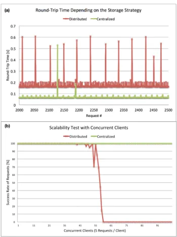
We compare both access types described above and show the round-trip time for each requests in Figure 3 part (a). First, each request is sent to the SC that will collect the
distributed data on the SPs. For this case, the average
round-trip time for 2500 consecutive requests is 186 mil-liseconds. In the second case, the client bypasses the SC and performs the requests directly on a storage peer stor-ing the whole dataset. In this case, the average round-trip time was 70 milliseconds. Not surprisingly the performance for direct communication is better. We can deduce that the time used by the coordinator for retrieving the distributed data and building the response is about 115 milliseconds. However this additional delay is not that substantial so that the distributed approach would be limiting certain
applica-1https://code.google.com/p/jcoap/
2https://github.com/1248/microcoap
tion scenarios.
6.2
Evaluating Concurrency
In this evaluation, we want to assess the difference be-tween the approaches in terms of concurrent requests. Sim-ilarly to the previous case, we performed requests using the distributed approach and directly to the SP. Figure 3 part (b) shows the results when having up to 100 concurrent clients running 5 requests. Not astonishingly, the centralized approach scales much better as the rate of the distributed approach drops as soon as the number of concurrent clients is reaching 50. This limitation can be explained by the number of sub-requests that are sent by the SC to the peers. Indeed each client request will result in up to three peer requests. It is very likely that the SC, having limited memory and CPU is not able to handle such an amount of requests.
6.3
Discussion
Using our in-network cloud storage significantly eases the storage of historical data in a sensor network. No specific in-frastructure is required for enabling the storage, as all avail-able devices contribute in the storage effort by offering their capacities. While gateways offer large amount of memory, other things only have a few kilo- or megabytes at disposal. The total amount of memory within the network could thus be very limited and not enough for satisfying the require-ments. In this case, we could imagine in the same way as for a cloud, to simply add more devices in the sensor network that will only be dedicated for storage, e.g. several Rasp-berry Pi offering cheap storage. The use of RESTful APIs on the peers storing time-series is an interesting alterna-tive to the common SQL. Indeed smart things being mostly composed of constrained devices do not have the ability of implementing SQL. REST allows standardizing the way his-torical data are exposed in sensor networks, this in a very
!" !#$" !#%" !#&" !#'" !#(" !#)" !#*" %!!!" %!(!" %$!!" %$(!" %%!!" %%(!" %&!!" %&(!" %'!!" %'(!" %(!!" +,-./01234"1356"789" +6:-68;"<" +,-./01234"1356"=646./3.>",.";?6"@;,2A>6"@;2A;6>B" =38;23C-;6/" D6.;2AE3F6/" (a) !" #!" $!" %!" &!" '!" (!" )!" *!" +!" #!!" #" ##" $#" %#" &#" '#" (#" )#" *#" +#" ,-../00"123/"45"1/6-/030"789" :4;.-<</;3":=>/;30"?'"1/6-/030"@":=>/;3A" ,.2=2B>=>3C"D/03"E>3F":4;.-<</;3":=>/;30" G>03<>B-3/H" :/;3<2=>I/H" (b)
Figure 3: Round-trip time for 500 consecutive quests (a) and scalability in terms of concurrent re-quests (b).
simple manner, and probably sufficient for most scenarios. The scalability test showed that the recomposition of data distributed on peers limits the number of concurrent clients. Nevertheless, it is unlikely that an average building manage-ment system issues such a high amount of history retrieval requests for a specific zone. Current machine-learning adap-tation techniques only perform a few queries per hour, for which our proposal is more than compatible.
7.
CONCLUSION
We have presented a system that composes a cloud-like storage space from several distributed smart things. Web technologies are at the heart of our system allowing a seam-less integration into future building automation systems re-lying on the Web-of-Things as federating paradigm. The most relevant advantages of our approach are self-adaptation and autonomy. The storage automatically adapts itself to environmental changes when devices are added or removed by dynamically recomposing the zones. No human in the loop is required thanks to the agent technique that ensures auto-promotion and synchronization. Another important aspect is the efficiency that is part of every decision that the system takes. Traffic reduction is an important issue that is too often left aside by commercial technologies. Working in the field of smart buildings where the final aim is to save energy, it would be difficult to defend an additional layer that is itself not optimized.
Performance tests showed that even using very constrained devices as storage peers allows to obtain satisfying results in terms of round-trip time and scalability. Still, we plan op-timizing the system in order to make it ready for future data-driven techniques requiring larger amount of historical data at higher frequencies. For this, we plan to compress the historical data exchanged between a storage coordinator and the peers, in order to accelerate the retrieval request. Furthermore, we intend to deploy our system for cloud stor-age in a real-life scenario to evaluate the splitting/merging strategy in a realistic situation.
8.
ACKNOWLEDGMENTS
The authors are grateful to the Swiss Hasler Foundation and to the RCSO grants from the HES-SO financing our research in this exciting area of smart buildings.
9.
REFERENCES
[1] influx db. http://influxdb.com/. [2] Json schema. http://json-schema.org/. [3] Stormdb. https://www.stormdb.com/.
[4] D. Difallah, P. Cudre-Mauroux, and S. McKenna. Scalable anomaly detection for smart city
infrastructure networks. IEEE Internet Computing, 17(6):39–47, 2013.
[5] D. Guinard. A Web of Things Application Architecture - Integrating the Real World into the Web. PhD thesis, ETHZ, 2011.
[6] K. Hartke. Observing resources in coap. draft-ietf-core-observe-14, 2014.
[7] G. Mathur, P. Desnoyers, P. Chukiu, D. Ganesan, and P. Shenoy. Ultra-low power data storage for sensor networks. ACM Transactions on Sensor Networks, 5(4):33:1–33:34, November 2009.
[8] A. Rahman and E. Dijk. Group communication for coap. draft-ietf-core-groupcomm-20, 2014.
[9] A. Ridi, N. Zakaridis, G. Bovet, N. Morel, and J. Hennebert. Towards reliable stochastic data-driven models applied to the energy saving in buildings. In Proceedings of the International Conference on Cleantech for Smart Cities and Buildings (Cisbat ’13), 2013.
[10] Z. Shelby, K. Hartke, and C. Bormann. Constrained application protocol (coap). draft-ietf-core-coap, 2014. [11] B. Sheng, Q. Li, and W. Mao. Data storage placement
in sensor networks. In Proc. of the 7th ACM
international symposium on Mobile ad hoc networking and computing, pages 344–355, 2006.