HAL Id: hal-02048193
https://hal.archives-ouvertes.fr/hal-02048193
Submitted on 27 Mar 2019HAL is a multi-disciplinary open access archive for the deposit and dissemination of sci-entific research documents, whether they are pub-lished or not. The documents may come from teaching and research institutions in France or abroad, or from public or private research centers.
L’archive ouverte pluridisciplinaire HAL, est destinée au dépôt et à la diffusion de documents scientifiques de niveau recherche, publiés ou non, émanant des établissements d’enseignement et de recherche français ou étrangers, des laboratoires publics ou privés.
composite stiffener debonding. Part 1: Non-specific
specimen level
Julien Bertolini, Bruno Castanié, Jean-Jacques Barrau, Jean-Philippe Navarro
To cite this version:
Julien Bertolini, Bruno Castanié, Jean-Jacques Barrau, Jean-Philippe Navarro. Multi-level experi-mental and numerical analysis of composite stiffener debonding. Part 1: Non-specific specimen level. Composite Structures, Elsevier, 2009, 90 (4), pp.381-391. �10.1016/j.compstruct.2009.04.001�. �hal-02048193�
MULTI-LEVEL EXPERIMENTAL AND NUMERICAL ANALYSIS
OF COMPOSITE STIFFENER DEBONDING
PART 1 : NON-SPECIFIC SPECIMEN LEVEL
Julien BERTOLINI**, Bruno CASTANIÉ*, Jean-Jacques BARRAU*, Jean-Philippe NAVARRO**.
* Université de Toulouse,UPS ; LGMT (Laboratoire de Génie Mécanique de Toulouse); Bat3PN, 118, route de Narbonne, F-31062 Toulouse, France
** Airbus France, 316 Route de Bayonne, F- 31000 Toulouse, France.
Abstract.
A multi-level analysis of skin/stiffener debonding is used for the fuselage design of future aircraft during postbuckling. The specimens composed of a laminate (the skin) to which an over-thickness (the flange) had been added were subjected to four-point bending, which led to interface failure between the flange and the skin. These tests were performed with several configurations and parameters, such as the orientation of the plies located at the interface, tem-perature (-50°C, 20°C and 70°C), ageing and manufacturing mode: co-cured or co-bonded. The flange shape (tapered or not) and thickness were also considered. Test data are presented and analyzed and critical configurations are identified. Finite element models were developed and the flange debonding loads computed, firstly by use of cohesive models and then through a fracture mechanics approach (Virtual Crack Closure Technique). In both cases, the Benzeg-gagh-Kenane criterion was selected and proved its efficiency but the fracture mechanics approach was an order of magnitude less time consuming, which will enable future modelling to include larger sizes.
* Corresponding author: [email protected], Tel: 33 (0)5.61.33.81.16. Fax: 33.(0)5.61.55.81.78.
Keywords.
1 - Introduction
The coming generations of aircraft structures will be made of all-composite materials but the traditional design composed of stiffeners, frames and thin skins will be kept. However, the stiffeners of metal structures are riveted whereas composite technology allows the stiffeners and skin to be manufactured together. Stiffened aeronautical structures are intended to allow for postbuckling, thus permitting a lighter structure. Postbuckling is allowed within the flight envelope for metal structures but only beyond limit loads for composite structures. Conse-quently, only static justification is required. In the postbuckling phase, the appearance of buck-les and a redistribution of the forces in the stiffener [1] lead to very localized overstresses at the stiffener/skin interface. Thus, the final failure of these structures may occur by stringer debonding between stiffener flanges and the skin of the fuselage [2], [3], [4]. Li et al [5] define an understanding of this phenomenon as the crucial link for the design of composite structure airframes. However, the scales at which debonding and postbuckling occur are very different: of the order of 100 mm for buckles and of the order of 0.1 mm for debonding. The modelling problem posed by multiple scales will be considered in the second part of this two-part article. Initially, analytical methods were proposed which enabled local bending moments and then local stresses to be calculated from out-of-plane displacements for the shear buckling case [6], [7]. As the accuracy of these methods was not sufficient, finite element methods were pro-posed. Krueger and Minguet [8] suggested using fracture mechanics to predict debonding. The modelling was done by finite elements and the Virtual Crack Closure Technique method was used to determine energy release rates and mode distribution [9]. Debonding initiation was determined by the Benzeggagh-Kenane mixed criterion, which seems pertinent for carbon-epoxy laminates [10]. These authors performed debonding tests at the elementary level for simple and combined loads to validate the choice of the approach. They used a non-specific specimen composed of a skin and a flange [11] initially proposed by Minguet [12]. The same
type of specimen and the same criterion were re-used by Camanho and Dàvila to validate their approach using cohesive elements and a bilinear damage law ([13], [14]). A stiffener debond-ing study was also carried out by Wagner and Balzani, again usdebond-ing cohesive elements but with an exponential law [15]. Both methods seem to have reached maturity and appear to give satis-factory results. Other methods have been put forward (Strain Invariant Failure Theory [16] and Strain energy density [17]) but remain to be validated for the problem at hand. To sum up, the various authors involved have focused on determining local criteria and numerical approaches that deal with the problem on different scales.
The analysis presented here forms part of a multi-level approach, details of which can be found in [18]. It includes experiment and computer simulation and is based on a "pyramid of tests" methodology (Figure 1 and [21]). The base of the pyramid is a purely experimental level concerning interface characterization tests for a given material. The second level uses non-spe-cific test pieces, i.e. specimens that are representative of a technology (e.g. co-cured or bonded assemblies) but independent of any particular programme or aircraft zone. The level above this concerns elements or structural details. Analyses at element and panel level will be presented in part 2. The last step would be to go from the scale of panels used for certification to compu-tation of the complete aircraft in postbuckling but this step needs methods to be developed that will reduce the computing time required by an order of magnitude [22].
This part of the paper presents the studies performed at non-specific specimen level. The specimens used by Krueger et al [11] and subjected to 4-point bending proved to be pertinent to the study of the debonding induced by postbuckling in stiffened composite structures. In particular, the introduction of composite fuselages means that wet ageing, manufacturing methods, local designs and the effects of temperature (from -50°C to +70°C) have to be taken into consideration. The number of tests to be carried out is therefore large and the cost would be prohibitive if performed at higher levels. The range of tests performed will be presented in
this first part. The size of the specimens also makes an initial validation of the Benzeggagh-Kenane criterion possible and allows a comparison between the fracture mechanics or cohesive element methods to be made using a commercial code (Abaqus [19]) so that a methodology applicable to the higher structural levels can be chosen.
2 - Experimental Study
2.1 - Description of specimens and test.
The geometry of the specimens is illustrated in Figure 2. The specimens were manufac-tured by manually laying up unidirectional, 134 g/m², plies of T700/M21 pre-impregnated laminate.
Two ways of manufacturing the flange were studied: co-cured (flange laid up at the same time as the skin) and co-bonded. In the case of co-bonding, the skin was polymerized first and the flange was laid up and placed on the skin with an adhesive film between the two parts. A second polymerization was thus necessary for these specimens. The local geometry was ana-lyzed by varying the thickness of the flange: 1.82 or 2.34 mm (14 or 18 plies) and varying the local shape: straight edges or tapered edges. The behaviour of two types of interface, 0°/0° and 45°/-45°, was analyzed.
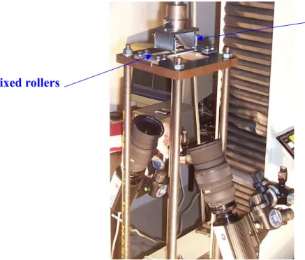
Four-point bending tests for which the upper supports were mobile and placed 72 mm apart and the lower supports were fixed 110 mm apart (Figure 3) were considered. Four-point was preferred to three-point bending in order to limit the risk of breaking the skin. Out-of-plane displacements were analyzed by digital image correlation. The load cell of the machine sup-plied the bending force. The start of cracking was visually detected using a CCD camera that filmed the side of the specimen, locally painted in white. The mechanical behaviour was glo-bally similar for all specimens of the test matrix according to the type of interface. Typical responses were analyzed through curves of force versus displacement at the supports.
Environmental effects were studied by performing tests at -50°C, 20° (room tempera-ture) and 70°C. The tests at -50°C and 70°C took place in a self regulating thermal chamber. To check stability of temperature in the specimens, two specimens were fitted with thermocou-ples in their core and on their surface before being placed in the thermal chamber. The curves of core and surface temperatures versus time showed that 20 minutes in the chamber was suffi-cient to ensure a uniform, stable temperature (-50°C or 70°C) in the specimens. Some speci-mens also underwent wet ageing at 70°C and 85% humidity. The temperature and humidity correspond to the requirements for aeronautical certification. The 85% humidity is known as the "objective rate". It is practically never reached on structures in flight as this relative humid-ity is found in very few places in the world and moisture absorption is reversible. The ageing time to reach saturation for our specimens was 4 months. The matrix of tests performed together with the number of specimens made is given in Table 1.
2.2 - Typical responses.
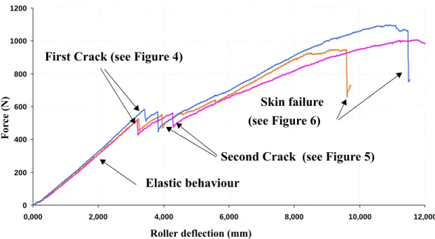
Three curves obtained for specimens with straight edges, interface 0°/0° at room tempera-ture are given in Figure 4.
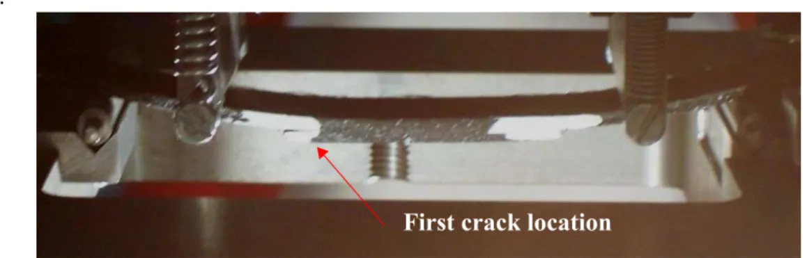
The first phase corresponds to linear behaviour of the specimen. This phase is interrupted by the appearance of a crack between the flange and the skin on one side only of the flange (Figure 5). The side that cracks first varies among specimens and seems to depend on the inac-curacy on the positioning of the specimen and imperfections that can vary from specimen to specimen. The appearance of the crack between the flange and the skin is characterized by a jump gap in the force/displacement curve. Increasing the load causes this first crack to propa-gate gradually, making the specimen unbalanced. After this, either the crack propapropa-gates until the flange comes away from the skin completely or a second crack appears on the other side of the specimen to make up for the imbalance (Figure 6). Increasing the load then leads to
com-plete detachment of the flange and final failure occurs by the plies of the skin breaking (Figure 7). For co-bonded specimens, the decrease in the forces when the first crack appears is greater and, in general, there is no second crack.
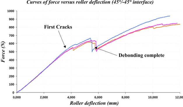
For 45°/-45° interfaces, debonding starts slowly at the interface between the flange and the skin (Figure 8). This produces a gradual reduction in the bending stiffness. The propagation is unsymmetrical and relatively restrained until loading goes beyond 600 N. The fibre bridging generally observed on the oriented interfaces and the fact that the fibres do not run in the deb-onding direction may explain this situation. At around 650 N, the crack opens up suddenly and debonding is abrupt. A post-mortem analysis showed an intralaminar fracture of the flange ply at 45° and propagation at the level of the 0° interface immediately above it (Figure 9). This was observed on all specimens. This debonding process is more gradual and could be recom-mended for the design of aeronautical structures. Nevertheless, the levels at which the first cracks appear are comparable to those for 0°/0° interfaces.
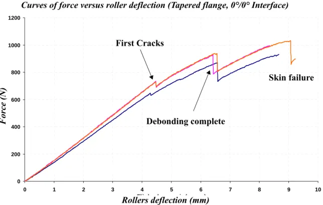
For the tapered flange, cracking does not occur directly at the interface between the flange and the skin but at the flange ply just above (see [12] and Figure 10). This crack thus cuts across the first ply before reaching the interface. Propagation is then very gradual and leads to complete debonding of the flange. The same overall types of behaviour were observed for aged specimens and at the various temperatures.
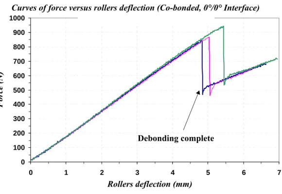
The response for a co-bonded specimen with straight edges with 0°/0° interface at room temperature is shown in Figure 11. For this type of interface, the behaviour is different from that of co-cured specimens. The elastic zone before cracking starts is much larger (+55% on average) but, once the crack starts, debonding propagates very fast along the whole length of the flange. The failure of the co-bonded joint occurs by cohesive fracture (Figure 12). Tapering the flanges in the co-bonded configurations had the same effects as in the co-cured configura-tions.
For the interfaces at 45°/-45°, the co-bonded specimens showed the same behaviour as that represented in Figure 8. In this case, the layer of adhesive did not provide any significant gain as the initial crack did not start at the bonded interface but at the interface of the 45°/90° plies in the flange.
2.3 - Manufacturing and design comparison at room temperature.
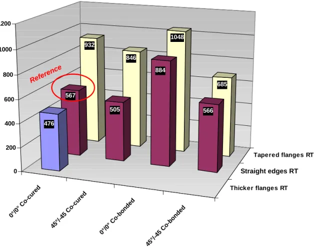
For aeronautical composite structures, the "no-crack growth" principle is used as a design guideline. Thus, the load corresponding to the onset of delamination is used as a crite-rion for comparing the different configurations proposed. Averages of tests results is shown in Figure 13. Scatter of the results was small, reaching +/- 15 % for the least favourable case (ref-erence case) and +/-2% for the tapered, 0°/0°, co-bonded flange. It was of the order of +/- 5% in general, with lower scatter for the co-bonded specimens.
The reference case corresponds to the simplest fabrication (specimen with straight edges) and a 0°/0° interface. When the flange thickness is increased, the crack appears for 16% lower loading. On the other hand, in all cases, the presence of tapering delays the onset of dela-mination. The greatest increase is + 64% with respect to the reference case. It is thus notewor-thy that local design is of paramount importance for the resistance of the structure. The tapered shape should be recommended despite the difficulty of manufacturing. At the interface, con-trary to usual expectations, the 45°/-45° configuration systematically leads to early fracture onset (-38% specimen with straight edges , co-bonded).
This can be qualitatively attributed to the fact that local stiffness is modified when the stacking sequence changes. Moreover, material qualification tests have shown that the initial energy release rates are equivalent for both interfaces. The possible advantage to be gained from using the 45°/-45° configuration is one of propagation but, by its very nature, this is in opposition to the "no-crack growth" design principle. As for the choice of manufacturing
method, in spite of the cost of the extra polymerization step, the co-bonded solution clearly has the advantage (+ 56% for specimen with straight edges and + 12% for tapered flanges). The variability among solutions is high: with respect to the reference case, the tapered flange, co-bonded solution gives a gain of + 84%.
2.4 - Influence of ageing and temperature.
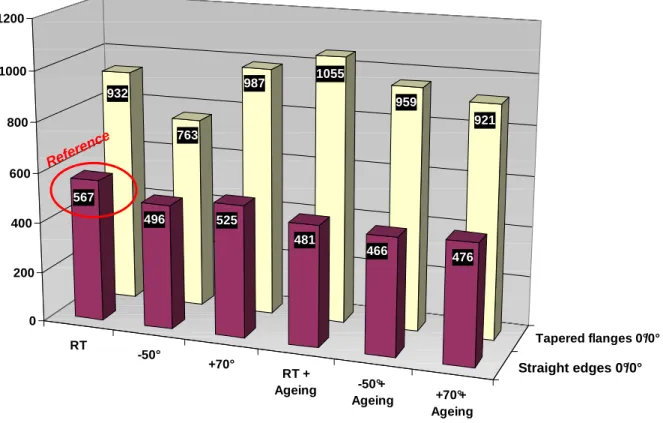
The influence of ageing and temperature on the onset of delamination for co-cured spec-imens is presented in Figure 14. For the sake of clarity, only the results with a 0°/0° interface are shown, given that the trends concerning the onset of delamination do not change with the nature of the interface. In terms of general specimen behaviour, the forms of damage and the fractures observed are not different from those observed at room temperature on non-aged specimens. However, the loads at which the first separation between the flange and the skin is observed vary with temperature and ageing. The greatest scatter (13.8 %) is obtained for the case of a specimen with straight edges at -50° and the smallest (1%) for the same configuration but with ageing. The average order of magnitude of the scatter is around 5 %. For specimens with straight edges, the tests show that very low temperatures (-50°C) constitute the critical case whether the specimen is aged or not. The loss is about 12 % in the non-aged configuration and only about 3% in the aged configuration. It can thus be noted that temperature sensitivity is lower for the aged configuration.
The failure levels for aged specimens with tapered edges are greater than those for simi-lar non-aged specimens. This may be due to the facts that the specimens were made from dif-ferent batches of raw materials and that the taper was slightly longer on the aged specimens. For this type of specimen, it is probable that the influence of the local geometry is more signif-icant than the influence of environmental conditions. In the case of non-aged specimens, the critical case is at -50° and the reduction with respect to room temperature is 18%. In the case of
aged specimens, the sensitivity to temperature is again found to be reduced (12.7 %) but the critical value is obtained at 70°C (-4% with respect to -50°C). However, in this case, the dis-persion is too large for the trend to be considered definite. The criticality at -50°C was also observed at the level of specimens with crossed interfaces. At 70°C, a reduction was also noted but was only of about 7%.
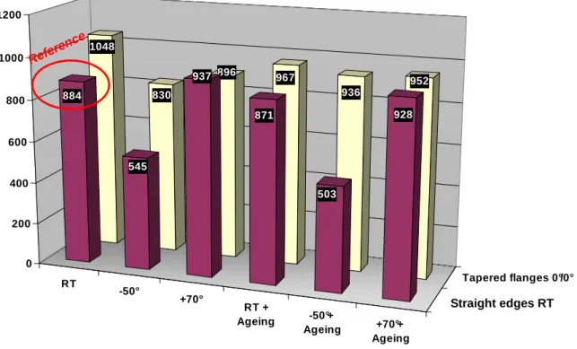
The influence of ageing and temperature on the onset of delamination for co-bonded specimens is presented in Figure 15. For the sake of clarity, only the results with a 0°/0° inter-face are shown, given that the trends concerning the onset of delamination do not change with the nature of the interface. As for the co-cured configurations, the reference corresponds to tests carried out at 20°C on non-aged, specimen with straight edges and a 0°/0° interface. In the case of co-bonded configurations, the temperature is the most influential factor. The critical temperature is still -50°C but the reductions observed are larger than in the co-cured case. The loss of strength is 38% for non-aged specimens and reaches 43% on aged specimens. In the case of solutions using tapering, the lowest temperature again corresponds to the critical case but the influence of environmental conditions seems less noticeable. The advantage of co-bonding over co-curing does not appear to be decisive when environmental effects are included (only +8 % for the case with ageing, - 50°C).
2.5 - Conclusion on the experimental study.
The critical configuration for co-cured and co-bonded technologies is the case with age-ing and low temperature for this material. Composites generally have better in-plane properties at -50°C than at 70°C. In our application, it is the "out-of-plane" behaviour of the laminate, and thus the resin, that is important. The embrittlement of the resin at low temperatures could explain this criticality. A noteworthy consequence is that, although the gains are high (+ 56%) for co-bonded technology at room temperature, after wet ageing and at -50° the gain is only
8%. For this critical case, the advantages provided by the co-bonded solution are practically negligible.
3 - Numerical Study
The aims of the numerical study were (i) to confirm the suitability of the de Benzeggagh-Kenane criterion proposed by Krueger et al [11] and to test the influence of the paramerer η, and (ii) to make a comparison at the elementary, non-specific specimen level between the cohesive element and fracture mechanics computing methods found in the literature. The choice made at this level conditions the choice of modelling at the higher level (Figure 1).
3.1 - Finite element models description.
The Abaqus software [19] has been used and the model is shown Figure 16. Theoretically, all specimens have two symmetrical planes, so it is possible to simplify the structure by use of such symmetries. Nevertheless, some defects and misalignments imply that a crack comes ear-lier than the other. Therefore, the initial symmetry does not exist after the first crack. In order to avoid any problems due to the debonding, no symmetry has been taken into account and specimens have been fully modelled. Geometries have been measured after manufacturing and real shapes have been also modelled. Boundary conditions are defined from contacts between supports (rollers) and specimens. Contact conditions are used between rollers and specimens. A hard contact is used along the normal direction and a free sliding for the tangential behav-iour. An augmented Lagrange method is used to solve contact equations. Each support is mod-elled by an analytical surface. To balance the model and avoid a free sliding between specimens and rollers, front faces of each specimen are constrained along the rolls directions. Loading was performed by an imposed displacement to a point connected with rigid links to the moving rollers.
The mesh was refined around the points of contact with the supports in order to make the models converge easier, and at the edges of the flanges so that the interface behaviour could be correctly modelled. The skin and flange were modelled using SC8R reduced integration "3D continuum shell" elements, allowing the out-of-plane representation. Only a single element is necessary in the thickness direction but the tapered flanges were modelled with two elements to better represent the stiffness at the extremities of the tapers. Each mesh element was about 1 mm² in the refined zones and the flange mesh was coincident with the skin mesh. The model of the skin/flange interface behaviour was based either on damage mechanics or on fracture mechanics.
A first model using cohesive elements was developed. Decohesion between the flange and the skin was modelled through a bilinear damage law [23], as illustrated in mode 1 in Figure 17. The law was implemented over three-quarters of the length of the flange (to allow decohe-sion at one side only) in cohesive elements of zero thickness. In practice, the use of cohesive elements requires a precise choice of four parameters: the interface pseudo stiffness Knn, the maximum equivalent stress of initiation, the critical energy release rate, which is equal to the area under the damage law, and the mesh size. The Benzeggagh-Kenane criterion [10] in mixed mode 1 and 2 was implemented as in Camanho et al. [13] and gave the area under the damage law (Figure 17):
(eq 1)
The terms indexed C are the critical values of the energy release rate and were obtained
from DCB and ENF [18] tests. For co-cured, et ; for
co-bonded : et .
The coupling coefficient η seems to be adequate to a fibre/matrix pair [10]. For the carbon GC G1 C G2 C G1 C – ( ) G2 G1+G2 --- η ⋅ + = G1 C 262J m⁄ 2 = G2 C 1360J m⁄ 2 = G1 C 1130J m⁄ 2 = G2 C 2870J m⁄ 2 =
fibre/epoxy resin combination it was possible to fix it arbitrarily at 1.5. In the early phases of an aeronautical programme it is necessary to pre-dimension the structures without knowing the final choices of materials or the definitive dimensions. A sensitivity study was therefore car-ried out a posteriori on the parameter η.
The initiation stress was defined by Hashin's quadratic criterion:
(eq 2)
where σN is the transverse traction strength (equal to 60 MPa) and the Interlaminar Shear Strength (ILSS) is 110 MPa.
A high value of the interface pseudo-stiffness Knn is expressed as an increase in the initial slope and leads to a stabilization of the results as noted by Turon et al. [14]. However, too high a value leads to problems of convergence connected with a deterioration of the conditioning of the tangent stiffness matrices. Knn = 106 N/mm3, a value recommended by Camanho et al [13],
was chosen in the present study. Once these parameters had been fixed, the propagation could be illustrated in one dimension by a series of damage curves, the concentration of which depended on the number of elements "active", i.e. partly damaged (Figure 17). The number of active elements depends on the mesh density and numerical convergence is observed when the density becomes sufficient [24]. In our case, convergence was obtained for a number of active mesh elements greater than or equal to 4, which gave an element size of 0.2 mm.
A second model, using fracture mechanics and computing the distribution by mode using the VCCT method [25], was used (see Figure 18). The efficiency of this type of modelling relies on prior knowledge of location of crack initiation, which is the case here, and on the hypothesis of non-perturbation caused by the presence of an initial crack. The VFA method proposed by Abaqus [19] allows node disconnections in order to model the debonding when the criterion is reached, by using contact elements which also avoids any penetration between
σ33 2 σN 2 --- ( )τ31 2 τ 32 ( )2 + ILSS2 ---+ = 1
the debonded area and the skin. A sensitivity study has been made on the pre-crack length and the mesh size [18] and shows that these parameters have little influence. The size was therefore fixed at 1 mm and the pre-crack at 0.5 mm.
3.2 - Finite element models/ tests comparison.
The curves of force vs displacement of the upper rolls are illustrated in Figure 19 for the test specimens with straight edges at room temperature. The results provided by the cohesive approach and the VCCT computation are also given. Globally, the computed stiffness corre-lates correctly with the tested stiffness up to the debonding phase. For the cohesive model, Hashin's criterion is reached very early (around 100 N), which is explained by the typical, very high, local interlaminar stresses. However, from a simulation standpoint, this early non-linear-ity makes it necessary to reduce the time steps, which greatly increases the computing time (5 hours) for the cohesive method. The first element is only completely damaged at 525 N, when the Benzeggagh-Kenane criterion is fully satisfied. Since the VCCT method is based on practi-cally the same physics, it is logical to find a value of 528 N when the criterion is reached. The experimental value for the start of crack propagation (567 N on average) was identified by ana-lyzing the variation in the derivatives of the displacement obtained by digital image correlation and by visualization of the side. The difference between simulation and test was 7.4 %, which is acceptable. The propagation was relatively stable when calculated by the cohesive method and more unstable with the VFA method, for which computation up to debonding only took 5 minutes. The correlation was not so good in the propagation phase, probably because of the appearance of fibre bridging and the occurrence of a second crack at the other edge of the flange. After debonding, only the stiffness of the skin remained but the calculation was deliber-ately stopped at this stage. A sensitivity study was performed on the exponent η of the Benzeg-gagh-Kenane law by the cohesive method (Figure 19). Globally, the responses in terms of
initiation and propagation were very similar, which can be attributed to the predominance of mode 1 in the initiation of propagation.
The results of the numerical simulations are given in Table 2 and compared with the tests in the case of co-cured specimens. The two types of modelling correlate well with the test results with an error of less than 9 % in all cases. Similar results were obtained for the VCCT method alone with adhesive at the interfaces [18].
3.3 - Conclusion on the numerical study.
The Benzeggagh-Kenane criterion was validated and proved to be robust for tests on non-specific specimens, including in the early phases of a programme. Both methods showed the same aptitude for predicting the onset of debonding. In terms of propagation, the cohesive ele-ments method was much more stable but neither of the models successfully represented the fibre bridges or the change of interface. However the two methods differed by an order of mag-nitude in computing time for small-sized problems. Thus, for calculating structures of large dimensions, the cohesive elements method is not suited to the industrial problems that arise. In the certification and sizing of composite structures, the "No crack growth" principle is used and, thus, only the onset of delamination is really important. Moreover, in this case as in many others, the position where debonding starts is known, either from previous experience or from tests, and the principal limitation of fracture mechanics is not really a problem in practice.
4 - CONCLUSIONS
In the framework of a multi-level approach, tests on non-specific specimens enabled us to determine critical configurations in terms of debonding for a given fibre/matrix combina-tion. In the case presented (T700/M21), the wet ageing configuration at -50°C was the most
unfavourable. The contribution made by an adhesive joint in the critical case proved to be small, only 8 %, whereas the manufacturing cost is much higher in this case. Tapered edges are, generally speaking, an advantage but the industrial implementation of these solutions is difficult. In any case, the methodology presented here, in terms of specimen type and tests, is indispensable for the choice of a new material in a composite structure that is subject to debonding (stiffened panels, corners, etc.). It would be interesting to follow up this analysis for fatigue. From a modelling point of view, the Benzeggagh-Kenane criterion has shown that it is relevant and can be used in the upstream phases of a programme. However, the temperature dependence law for aged configurations remains to be established. Moreover, the choice of fracture mechanics imposes itself for industrial applications because of its reduced computing time, particularly when as, in the case studied, the position of the onset of debonding is known and it is not useful to know the propagation behaviour. Overall, the studies performed at this scale enable the first choices of technology and simulation to be made in the very early phases of an aeronautical programme, thus reducing the risks while shortening the design cycles.
5 - REFERENCES.
[1]Pevzner P., Abramovich H., Weller T.: Calculation of the collapse load of an axially compressed laminated composite stringer-stiffened curved panel–An engineering approach. Composite Structures 83 (2008) 341–353
[2]Stevens K.A., Ricci R., Davies G.A.O.: Buckling and postbuckling of composite structures.Compos-ites 26 (1995) 189-199.
[3]Sheppard A. T., Leong K.H., Kelly D.W., Raju J.: Rib separation in postbuckling stiffened shear panels. Composite Structure 43 (1998) 339-352.
[4]Zimmermann R., Klein H., Kling A.: Buckling and postbuckling of stringer stiffened fibre compos-ite curved panels – Tests and computations Composcompos-ite Structures 73 (2006) 150–161
[5]Li J., Dávila C. G., Chen T-K.: High Fidelity Failure Analysis for a Composite Fuselage Section, American Helicopter Society 57th Annual Forum, Washington, DC, May 9-11, 2001.
AIAA, Aircraft Engineering, Technology, and Operations Congress, Los Angeles, CA; UNITED STATES; 19-21 Sept. 1995. 1995
[7]Sharp D., Sobel L.: Novel composites for wing and fuselage applications. Speedy non linear analysis of postbuckled panels in shear (SNAAPS). Nasa/CR-097-206256, 1997.
[8]Krueger R., Minguet P.J.: Analysis of composite skin–stiffener debond specimens using a shell/3D modeling technique. Composite Structures, Volume 81, Issue 1, November 2007, Pages 41-59.
[9]Krueger R.: Virtual crack closure technique: History, approach, and applications Applied Mechanics Reviews 2004 Vol 57, Issue 2, pp. 109-143.
[10]Benzeggah M.L., Kenane M.: Measurement of mixed-mode delamination fracture toughness of unidirectional glass/epoxy composites with mixed-mode bending apparatus. Composite science and technology 56 (1996) 439-449.
[11]Krueger R., Cvitkovitch M. K., O’Brien T. K., Minguet P.J.: Testing and analysis of composite skin/stringer debonding under multi-axial loading. Journal of Composite Materials 34 (2000) : 1263-1300.
[12]Minguet PJ, O’Brien T.K.: Analysis of test methods for characterizing skin/stringer debonding fail-ures in reinforced composite panels. Composite Materials: Testing and Design (Twelfth volume) ASTM STP 1996;127(4):105–24
[13]Camanho P. P., Davila C. G., De Moura M. F.: Numerical Simulation of Mixed-Mode Progressive Delamination in Composite. Journal of Composite Materials 2003; 37; 1415-1438.
[14]Turon A., Camanho P.P., Costa J., Davila C.G.: A damage model for the simulation of delamination in advanced composites under variable-mode loading. Mechanics of Materials 38 (2006) 1072–1089 [15]Wagner W., Balzani .C.: Simulation of delamination in stringer stiffened fiber-reinforced composite shells. Comput Struct (2007), doi:10.1016/j.compstruc.2007.04.018
[16]Tay T.E., Tan S.H.N., Tan V.B.C., Gosse J.H.: Damage progression by the element-failure method (EFM) and strain invariant failure theory (SIFT). Composites Science and Technology 65 (2005) 935– 944
[17]Persson E., Madenci E., Eriksson I.: Delamination initiation of laminates with pin-loaded holes. Theoretical and Applied Fracture Mechanics 30 (1998) 87-101.
[18]Bertolini J. Contribution à l’analyse expérimentale et thèorique des ruptures de structures compos-ites en postflambement par décollement de raidisseurs. Thesis Université Paul Sabatier, Toulouse, April 2008 (in french) http://thesesups.ups-tlse.fr/
[19]ABAQUS/Standard. Analysis User’s Manual. Release 6.6, 2007.
[20]Bertolini J., Castanié B., Barrau J.J., Navarro J.P. : An experimental and numerical study on omega stringer debonding. Composite Structure 2008, In press.
[21]Castanié B., Barrau J.J., Jaouen J.P., Rivallant S.: Combined shear/compression structural testing of asymmetric sandwich structures, Experimental mechanics, Vol 44 (5), pp 461-472, Octobre 2004. [22]Kling A., Degenhardt R., Zimmermann R. : A hybrid subspace analysis procedure for non-linear postbuckling calculation. Composite Structures 73 (2006) 162–170.
[23]Allix O., Ladeveze L.: Interlaminar interface modelling for the prediction of delamination. Com-posite Structures 22 (1992) 235-242.
[24]Blackman B.R.K, Hadavina H., Kinloch A.J., Williams J.G.: The use of cohesive zone model to study the fracture of fibre composites and adhesively-bonded joints. International journal of fracture 119 (2003) 25-46.
[25]Krueger R. Virtual crack closure technique: History, approach, and applications. Applied Mechan-ics Reviews, 57(2004) 109-143.
FIGURES
Figure 2: Specimen overall geometry (straight edges and tapered flanges), unit: mm.
Figure 3: Four point bending test with digital image correlation set. Flange Skin 30 0° 0° 120 45 45 120 Thickness 2.08 (16 plies) Thickness 1.82 or 2.34 (14 or 18 plies) Thickness 1.82 2 0
Straight edges Tapered flange
Mobile rollers
Figure 4: Typical responses for 0°/0° interface, co -cured (3 specimens). 0 200 400 600 800 1000 1200 0,000 2,000 4,000 6,000 8,000 10,000 12,000
Flèche des appuis (en mm)
Ef fo rt ( e n N )
First Crack (see Figure 4)
Second Crack (see Figure 5) Skin failure Elastic behaviour (see Figure 6) Roller deflection (mm) F o rc e (N )
.
Figure 5: First debonding onset (0°/0° interface).
Figure 6: Second debonding onset (0°/0° interface).
Figure 7: Pattern just before final failure of the skin (0°/0° interface).
First crack location
Second crack location
Figure 8: Typical response for a 45°/-45° interface (3 specimens).
Figure 9: Pattern after complete debonding (co-cured, 45°/-45° interface).
Courbes Effort / Déplacements aux appuis Interface° 45/-45° 0 100 200 300 400 500 600 700 800 900 1000 0,000 2,000 4,000 6,000 8,000 10,000 12,000
Flèche aux appuis (en mm)
Ef fo rt ( e n N ) First Cracks Debonding complete Roller deflection (mm) F o rc e (N )
Curves of force versus roller deflection (45°/-45° interface)
Figure 10: Typical response for a tapered flange, co-cured and (0°/0°) interface (3 specimens).
Courbes Effort / Déplacements des appuis Tapered flange (0°/0°) 0 200 400 600 800 1000 1200 0 1 2 3 4 5 6 7 8 9 10
Flèche des appuis (en mm)
Ef fo rt ( e n N ) First Cracks Debonding complete Skin failure Rollers deflection (mm) F o rc e (N )
Figure 11: Typical responses for a specimen with straight edges, co-bonded and (0°/0°) interface.
Figure 12: Typical final pattern of co-bonded specimens.
Courbe effort / Déplacement aux appuis Co-bonded specimen 0°/0° 0 100 200 300 400 500 600 700 800 900 1000 0 1 2 3 4 5 6 7
Flèche des appuis (en mm)
E ff o rt ( e n N ) Debonding complete Rollers deflection (mm) F o rc e (N )
Figure 13: Comparison of first onset of delamination for specimens at room temperature. 0°/0 ° C o-cu red 45°/ -45 C o-cure d 0°/0 ° C o-bo nded 45°/ -45 C o-bond ed Thicker flanges RT Typical flanges RT Tapered flanges RT 932 846 1048 685 567 505 884 566 476 0 200 400 600 800 1000 1200 Refer ence Straight edges RT
Figure 14: Influence of ageing and temperature on first onset of delamination for co-cured specimens. RT -50° +70° RT + Ageing -50°+ Ageing +70°+ Ageing Typical flanges 0°/0° Tapered flanges 0°/0° 932 763 987 1055 959 921 567 496 525 481 466 476 0 200 400 600 800 1000 1200 Refer ence Straight edges 0°/0°
Figure 15: Influence of ageing and temperature on first onset of delamination for co-bonded specimens. RT -50° +70° RT + Ageing -50°+ Ageing +70°+ Ageing Typical flanges 0°/0° Tapered flanges 0°/0° 1048 830 896 967 936 952 884 545 937 871 503 928 0 200 400 600 800 1000 1200 Refer ence Straight edges RT
Figure 16: Finite element models.
Figure 17: Mesh density and cohesive modeling parameters illustration.
(a) Specimen with straight edges
(b) Tapered Flange Fixed rollers Loading point Moving rollers Refined area
Traction
Séparation
δδδδ
n 0 nt
Variation du déplacementZone d’éléments partiellement
endommagés en même temps
nn K IC
G
δ
nfStress Criterion
CFirst element fully debonded
Active elements (partially debonded)
Figure 18: Particularities of the Fracture mechanic model.
Figure 19: Typical comparison between finite element and test (specimen with straight edges, co-cured, room temperature).
Flange
Skin
Contact Elements
Pre-crack
Mesh size
0 100 200 300 400 500 600 700 800 900 1000 1100 0 2 4 6 8 10 12 Supports displacements (mm) F o rc e ( N )Tests (specimens with straight edges , co-cured)
VCCT,
η
= 1.5Cohesive :
η
= 1.5η
= 2η
= 1Cohesive : Damage initiation
Cohesive : First element fully damaged
TABLES
Table N° 1: Test matrix and number of specimen test ed.
Table N° 2: Test/computation comparison (onset of delamination). CONFIGURATION Co-cured 0°/0° Co-bonded 0°/0° Co-cured 45°/-45° Co-bonded 45°/-45° Straight Edges T°: –50°C 3 3 2 2 Tapered flange T°: –50°C 3 3 2 2
Straight Edges T°: 20°C (REF) 3 3 2 2
Thicker flange T°: 20°C 3 0 0 0
Tapered flange T°: 20°C 3 3 2 2
Straight Edges T°: 70°C 3 3 0 0
Tapered flange T°: 70°C 3 3 0 0
Straight Edges Ageing T°: –50°C 2 2 0 0
Tapered flange Ageing T°: –50°C 2 2 0 0
Straight Edges Ageing T°: 20°C 2 2 0 0
Tapered flange Ageing T°: 20°C 2 2 0 0
Straight Edges Ageing T°: 70°C 2 2 0 0
Tapered flange Ageing T°: 70°C 2 2 0 0
CONFIGURATION VCCT (N) Cohesive (N) Test mean (N) Difference (%) Straight edges (Co-cured) 567 528 525 7%
Tapered flange (Co-cured) 476 503 505 6%
Thicker Flange (co-cured) 517 463 468 9%
Cross-ply interface (co-cured) 706 708 702 1%
![Figure 1: Multi-level analysis of skin-stringer debonding [18].](https://thumb-eu.123doks.com/thumbv2/123doknet/12181414.314469/19.892.147.824.86.767/figure-multi-level-analysis-skin-stringer-debonding.webp)