HAL Id: hal-00946564
https://hal.archives-ouvertes.fr/hal-00946564
Submitted on 6 Nov 2018
HAL is a multi-disciplinary open access
archive for the deposit and dissemination of
sci-entific research documents, whether they are
pub-lished or not. The documents may come from
teaching and research institutions in France or
abroad, or from public or private research centers.
L’archive ouverte pluridisciplinaire HAL, est
destinée au dépôt et à la diffusion de documents
scientifiques de niveau recherche, publiés ou non,
émanant des établissements d’enseignement et de
recherche français ou étrangers, des laboratoires
publics ou privés.
Mechanical behaviour of plain-knit reinforced injected
composites : effect of inlay yarns and fibre type
Laura Balea, Gilles Dusserre, Gérard Bernhart
To cite this version:
Laura Balea, Gilles Dusserre, Gérard Bernhart. Mechanical behaviour of plain-knit reinforced injected
composites : effect of inlay yarns and fibre type. Composites Part B: Engineering, Elsevier, 2014, 56,
p.20-29. �10.1016/j.compositesb.2013.07.028�. �hal-00946564�
Mechanical behaviour of plain-knit reinforced injected composites:
Effect of inlay yarns and fibre type
Laura Balea, Gilles Dusserre
⇑, Gérard Bernhart
Université de Toulouse, Mines Albi, INSA, UPS, ISAE, ICA (Institut Clément Ader), Campus Jarlard, F-81013 Albi cedex 09, France
Keywords: A. Fabrics/textile B. Mechanical properties E. Knitting
E. Resin transfer moulding (RTM)
a b s t r a c t
This paper investigates the effect of inlay yarns and fibre type (E-glass, basalt, carbon) to improve the mechanical behaviour of plain knit reinforced composites (epoxy matrix). The tensile behaviour of the dry reinforcement was investigated in the wale and directions and has shown that the course-wise deformation is drastically reduced whereas the strength is strongly increased when inlay yarns are included. Fibre type has a weak effect on deformation and strength. For the composite material, pro-cessed by Liquid Composite Moulding, the carbon fibre reinforcement gives always the best results what-ever the testing direction. Inlay yarns decrease the 0! mechanical properties, whereas 45! and 90! are increased. Moreover a quasi-isotropic behaviour is obtained when using two inlay yarns, irrespective of the fibre types.
1. Introduction
Fibre reinforced composite materials are increasingly used in industrial applications requiring high specific mechanical proper-ties. They cover a large range of mechanical and physical properties due to the numerous parameters involved in their manufacturing. Amongst them, the fibre arrangement in the matrix has an impor-tant effect on the mechanical properties of the composite. Up to now, woven and unidirectional reinforcements are mainly used in industrial applications. The low curvature of the fibres confers high performance to the composite. However, issues related to fi-brous architecture remain, especially for composite forming. Com-plex shape parts manufacturing requires cutting and assembly operations, resulting in material wastage and high production costs. This leads also to a local weakening in assembly areas, mainly related to the reinforcement discontinuity. Therefore new reinforcement architectures were designed, and, amongst them, knitted fabrics meet the technical requirements for complex shapes forming. This technology enables the development of net-shape fabrics, including holed preforms. Knits are obtained by intermeshing loops of fibre yarns resulting in a high deformation ability compared with woven fabrics[1,2]thanks to the possibility to change the shape of the loops[3,4]. This deformation ability is especially suitable for stretch forming and deep drawing, since it allows to distribute homogeneously the textile deformation, avoid-ing local material heterogeneities in a savoid-ingle part[5,6]. A low strain
energy is required allowing wrinkles to appear lately in compari-son to woven fabrics [7,8]. Excellent properties for composite moulding are obtained, especially for stacking.
Knit reinforced composites exhibit also interesting impact behaviour properties. Stitches of adjacent layers overlap each other, reducing inter-laminar resin-rich areas and crack propaga-tion. The inter-laminar fracture toughness is then increased com-paring to woven and UD composites [9–12]. Indeed the delamination of knit composites involves both mode I and mode III crack propagation [12]. Compression-After-Impact tests high-light the high damage tolerance of knitted composites: they exhibit a relative compressive strength retention higher than woven com-posites[9].
However, knitted composites exhibit low in-plane mechanical properties, close to short fibres composites, because of the curva-ture of the fibres[13,14]. The compressive properties are isotropic and depend strongly on the matrix properties [15]. On the con-trary, the tensile properties are anisotropic and related to the rein-forcement. Up to now, most studies were focused on basic knitted structures such as plain, 1 ! 1 rib and Milano made of glass fibres. These investigations highlighted that the composite properties de-pend on knit architecture[16,17]and on knit geometrical parame-ters such as stitch size, stitch density and yarn length[16,18]. An initial fabric deformation before composite processing leads to an improvement of the properties in the stretched direction and to a loss of properties in the transverse direction[19]. However biaxial stretching before composite forming has a negligible effect[20]. It is then demonstrated that an improvement of the tensile proper-ties would require a modification of the fibre distribution in the ⇑Corresponding author. Tel.: +33 (0)5 63 49 33 09; fax: +33 (0)5 63 49 32 42.
material. No studies on the effect of the fibre type on the knitted composite behaviour are known.
In this paper, the effects of knit construction and fibre type on the composite tensile behaviour are investigated. Previous works [21,22] were focused on the two basic knitted reinforcements, plain and 1 ! 1 rib. This latter is made up of front and back stitches, leading to a three-dimensional structure and a higher deformabi-lity is then achieved than with plain-knit, only made up of front stitches. Plain structure confers the best tensile properties to the composite, especially in the wale-direction, due to a less isotropic fibre orientation distribution, and has been chosen as the starting point of the optimisation aiming to improve the composite mechanical properties [23–25]. Plain-knit composites are aniso-tropic with higher properties in the wale-direction. These rein-forcements have higher deformation ability in the course-direction. A correlation between fabric deformation ability and composite properties was carried out. The optimisation of the plain-knit architecture requires to reinforce the course-direction and to find a compromise with the deformation ability (reinforcing means adding straight yarns, what obviously decreases the exten-sibility). The knitting process allows to add non-knitted yarns in the course-direction into the fabric, thanks to inlay yarns obtained by two techniques: float loops[26]or tuck loops[26,27]. In this pa-per, the cross effects of inlay yarns, their number, and the fibre type on knitted fabric deformability and composite mechanical behaviour are investigated.
2. Materials and process
2.1. Fibres and resin
E-glass, basalt and carbon fibres are studied to highlight the ef-fect of the fibre type on the behaviour of the fabric and the com-posite. Glass and carbon fibres are the most widely used in the composite manufacturing industry. The former are mostly dedi-cated to mass production materials due to its excellent price-qual-ity ratio and the latter provide high cost structural materials, with excellent mechanical properties. Basalt fibres, considered as emer-gent, have interesting physicochemical properties and slightly bet-ter mechanical properties than glass fibres.
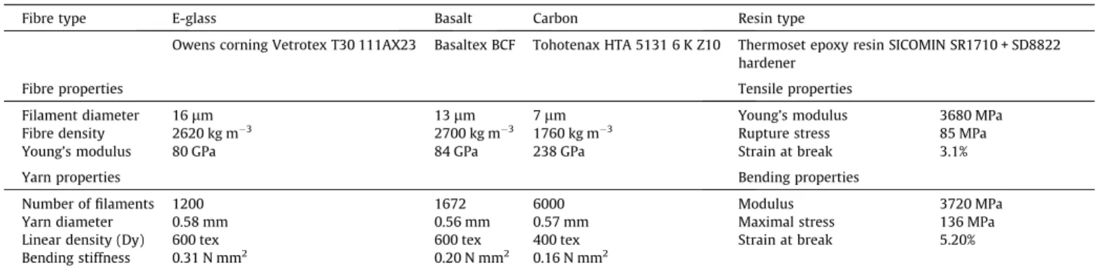
The yarn diameter is a key parameter of a knit, it controls the jamming of the loops[21]. In order to produce equivalent knitted fabrics, roving bobbins with a similar yarn diameter were chosen. This diameter is calculated from diameter and number of filaments by considering a hexagonal fibre packing. Fibres and roving prop-erties are given in Table 1. Glass and basalt fibres have similar properties and both rovings have the same linear density. However a smaller filament diameter confers to basalt yarns a lower bend-ing stiffness. Carbon fibres have thinner filaments and exhibit a
higher Young’s modulus and a lower density, that confer to the yarns lower bending stiffness and linear density.
The resin used is a two components epoxy system (SICOMIN SR 1710 resin with SD 8822 hardener) designed for resin transfer moulding processes. This system is characterized by a very low vis-cosity and high mechanical properties, conferring a high inter-lam-inar shear strength to the composite (Table 1).
2.2. Knitted fabrics
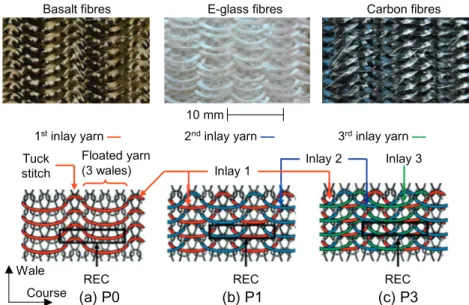
Knitting consists in intermeshing loops of yarns to produce fab-rics from a single or from several yarns. Weft-knitting refers to the knitting direction: the stitches are knitted successively in the weft-direction, also called course-direction. The loops are intercon-nected in the wale direction called also columns. Plain-knit, only made of front stitches, is the basic architecture (Fig. 1) in which in-lay yarns were added to reinforce the course-direction. Every four plain stitches, inlay yarns are linked to the knit by tuck stitches (Fig. 2). Between two consecutive tuck stitches, the inlay yarn forms a float loop. Basic plain-knit (P0) and plain-knits with one (P1), two (P2) and three (P3) inlay yarns per course were manufac-tured and are presented inFigs. 1 and 2.
All knits under study were produced from each fibre type with the same knitting parameters in order to get equivalent stitch sizes, given by the geometrical parameters defined inFig. 1. W, C and LY are respectively the average wale width, course height
and yarn length per stitch. W and C were calculated from fabric dimensions and number of stitches, whereas LYis calculated from
fabric weight and yarn linear density. The mean values calculated for all knits under study are W = 4.2 ± 0.4 mm, C = 2.5 ± 0.1 mm and LY= 17.5 ± 3.9 mm. The important dispersion of these
parame-ters (5–20%) is related to the properties of the different fibres. The stitch size depends on knitting parameters but also on the loop
Table 1
Fibre, yarn and resin properties.
Fibre type E-glass Basalt Carbon Resin type
Owens corning Vetrotex T30 111AX23 Basaltex BCF Tohotenax HTA 5131 6 K Z10 Thermoset epoxy resin SICOMIN SR1710 + SD8822 hardener
Fibre properties Tensile properties
Filament diameter 16lm 13lm 7lm Young’s modulus 3680 MPa
Fibre density 2620 kg m"3 2700 kg m"3 1760 kg m"3 Rupture stress 85 MPa
Young’s modulus 80 GPa 84 GPa 238 GPa Strain at break 3.1%
Yarn properties Bending properties
Number of filaments 1200 1672 6000 Modulus 3720 MPa
Yarn diameter 0.58 mm 0.56 mm 0.57 mm Maximal stress 136 MPa
Linear density (Dy) 600 tex 600 tex 400 tex Strain at break 5.20%
Bending stiffness 0.31 N mm2 0.20 N mm2 0.16 N mm2
(a)
(b)
(c)
Fig. 1. Plain-knit basic architecture (P0): (a) photograph of a basalt fabric; (b) testing directions and (c) representative elementary cell (REC) and geometrical characteristics of the loop.
static equilibrium, which is determined by the yarn mechanical properties, structure and size of the fabric: inlay yarns insertion in-creases W and LYby modifying the static equilibrium.
Due to the shape of the needle hooks and the high velocity of the needles, some fibres are damaged during knitting. If glass and basalt fabrics show a very low amount of broken fibres, it is larger in carbon fabrics and increases with the number of inlays. The fabric characteristics are given in Table 2. The thickness is measured under a 5 kPa pressure following the Bueno et al.[28] conditions. For similar yarn diameters, the thickness mainly de-pends on the fabric texture and less on the fibre type. Indeed the variations are due to the fibre rearrangement, facilitated by a lower diameter and bending stiffness of carbon fibres. The areal density is similar for glass and basalt knits, and lower for carbon fabrics, in agreement with their yarn linear density.
2.3. Composite laminates
The reinforcements aforementioned were processed by VARTM in an aluminium rigid closed mould coated with a semi-permanent release agent (Loctite 44-NC Frekote). A vacuum pressure of 1 mbar was applied into the mould by vents located at each corner and the resin was injected through an inlet located at the centre of the mould (Fig. 3). The resin injection was performed at room tem-perature and the laminates were cured at 60!C for 16 h on a heat-ing plate. The composite laminates characteristics are given in Table 3. P0 composites were manufactured with 3 reinforcing lay-ers to reach a fibre volume fraction close to 30%. P1 composites were manufactured with two layers providing the same fibre
content as P0. P2 and P3 composites contain also two layers as P1, but exhibit a higher fibre volume fraction. The porosity ratio varies between 2.6% and 10.1%. It is lower in P0 laminates, but no correlation can be made with the number of inlays. High ratios are mainly related to air bubbles entrapment during resin mixture. A careful selection of the specimen was carried out, so that the materials tested have the less voids as possible.
3. Mechanical behaviour of the knitted fabrics
3.1. Specimen and testing method
Uniaxial tensile tests were performed on knitted preforms in wale and course-directions according to NF EN ISO 4606
stan-E-glass fibres
Basalt fibres Carbon fibres
(a) P0
REC(b) P1
REC(c) P3
RECTuck stitch
Floated yarn (3 wales)
1stinlay yarn —— 2ndinlay yarn —— 3rdinlay yarn ——
Inlay 1 Inlay 2 10 mm
Inlay 3
Course Wale
Fig. 2. Photographs, schematic views and representative elementary cell (REC) of the knitted fabrics: (a) with 1 inlay yarn (P1); (b) with 2 inlay yarns (P2) and (c) with 3 inlay yarns (P3).
Table 2
Knitted fabrics characteristics.
P0 P1 P2 P3 Thx (mm) E-glass 1.60 ± 0.00 1.92 ± 0.06 2.22 ± 0.13 2.82 ± 0.75 Fabric thickness (measured under 0.005 MPa pressure) Basalt 1.55 ± 0.09 1.83 ± 0.06 2.20 ± 0.05 2.78 ± 0.75 Carbon 1.53 ± 0.03 1.80 ± 0.05 2.08 ± 0.03 2.62 ± 0.60 MS(g m"2) E-glass 792 ± 60 1028 ± 181 1382 ± 167 1589 ± 160
Areal density Basalt 797 ± 113 1044 ± 227 1337 ± 161 1572 ± 173 Carbon 566 ± 32 664 ± 136 874 ± 152 1072 ± 108 Upper mould Preform Vacuum outlets Injection intlet Resin tank Lower mould Spacer
Fig. 3. VARTM processing conditions.
Table 3
Composite plate characteristics.
Reinforcement P0 P1 P2 P3
Number of plies 3 2 2 2
Plate thickness (mm) E-glass 3.15 3.18 3.19 3.22 Basalt 3.15 3.17 3.19 3.21 Carbon 3.15 3.18 3.17 3.17 Fibre content (%) E-glass 31 29 38 43
Basalt 32 31 35 41
Carbon 32 30 37 42
Porosity (%) E-glass 2.8 5.4 7.1 5.4
Basalt 3.4 8.4 7.5 6.6
dard dedicated to uniaxial tensile testing of woven fabrics, since no standards concerning knitted fabrics are available. The fabrics were directly knitted at the testing sample size (300 ! 100 mm2)
since the knit cannot be cut without unravelling. A few courses of an elastomeric fibre were knitted on the long edges of the course-direction specimens to avoid unravelling while limiting its intrusiveness. The tests were carried out on an INSTRON 5800R electromechanical testing machine fitted out with pneu-matic grips at the constant crosshead displacement rate of 50 mm min"1. An acceptable dispersion of the experimental data
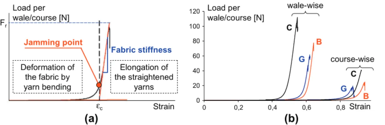
made it possible to select a representative load versus strain curve for the discussion, among the three available for each test condition. The results are given in load per wale or course versus true strain (Fig. 4).
3.2. Behaviour of a plain knit fabric
The behaviour of a knitted fabric can be divided into two main steps separated by a jamming transition phase (Fig. 4a). The first step involves a slipping of the yarns at the contact point between adjacent loops. A change of the loop shape occurs by yarn bend-ing and results in a linear behaviour with an important deforma-tion of the fabric under low loads. This phenomenon occurs until the jamming transition phase, in which a transverse compression of the yarns occurs due to fibres rearrangement at the cross-over. The yarns bending tends toward a limit while the tensile load in-creases. At the end of this phase, the stitch is fully jammed. The load is then carried out by the stitch legs, subjected to tensile stresses, whereas shear stresses increase in the cross-over areas. A fast increase of the load is thus observed, resulting in a second almost linear domain of the load–strain curve. The first step is characterized by a critical strain (
e
c) which corresponds to thestrain at the intersection of both linear domains. The last step is characterized by the fabric stiffness after full jamming of the stitches, corresponding to the slope of the curve, and by the fail-ure load.
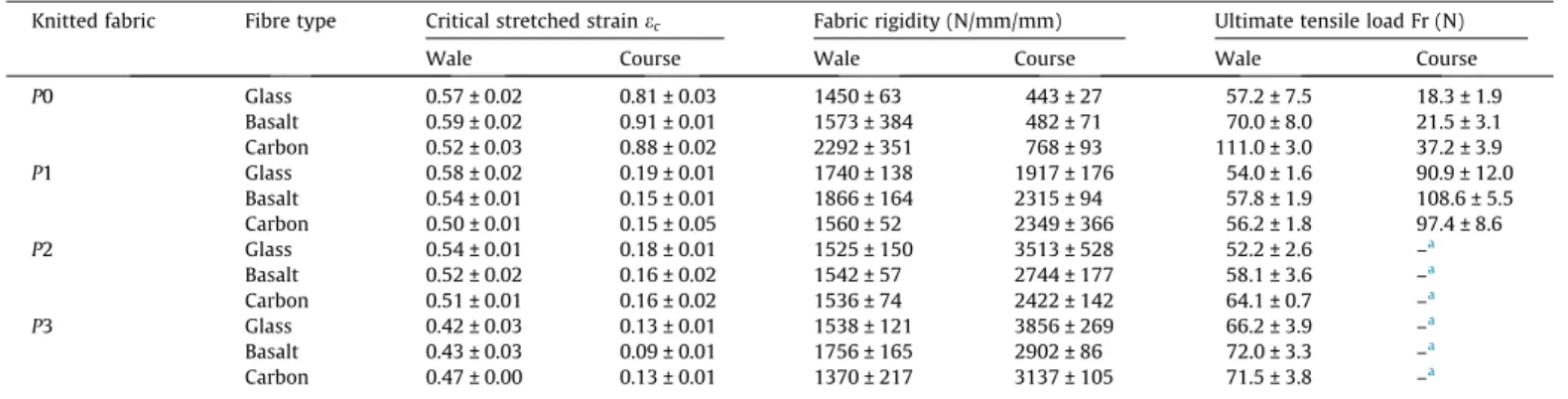
Fig. 4b illustrates the tensile behaviour of the plain-knit accord-ing to the loadaccord-ing direction and the fibre type fabrics (E-glass, ba-salt and carbon).Table 4reports the values of the characteristic parameters of the tensile behaviour. Irrespective of the fibre type and loading direction, plain-knit fabrics behave similarly. A higher deformation ability and lower mechanical properties are observed in the course-direction. These properties result from the loop geometry related to the knitting process: the yarns run along the courses and are interconnected in the wale-direction. In Fig. 5 are shown schematic views of the fabric structure at initial state and stretched in wale or course-directions. Stretched in the course-direction, the stitches lose their loop shape to take a curvy
form, whereas in the wale-direction, the stitches present a stretched loop shape at jamming. In the first step, considering the low loads involved, the fibre type has a negligible effect on the fabric macroscopic behaviour and the critical strains reached are similar for a given loading direction (Table 4). After jamming, one yarn per course is subjected to tensile stress while two yarns per wale are loaded. It explains the higher rigidity and the higher strength reached by plain-knits loaded in the wale-direction. In this part, the fibre type is the most influent parameter. Best prop-erties are obtained with carbon fibres whereas glass and basalt plain-knits exhibit similar properties despite the slightly higher values reached with basalt fibres.
3.3. Inlay yarn fabric behaviour
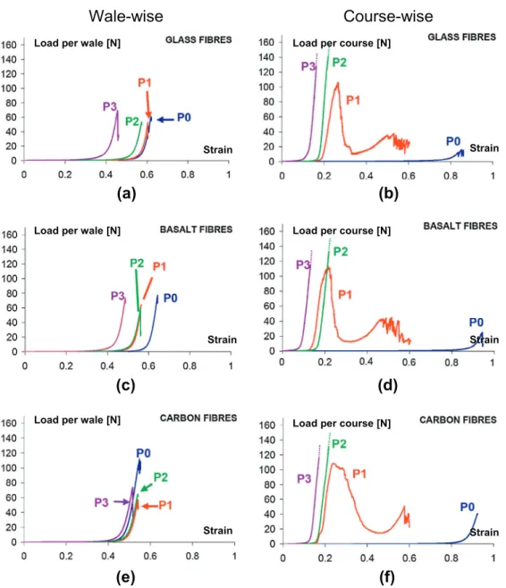
The tensile behaviour of plain-knits with inlay yarns is plotted in Fig. 6 and the properties are summarized inTable 4. In the wale-direction, the insertion of inlays tends to decrease the strain at jamming, but this effect is slight compared to the standard devi-ation of the experimental results. Each yarn diameter being similar to each others, the strain levels reached are of the same order of magnitude, irrespective of the fibre type.Fig. 5depicts a schematic view of a plain-knit with inlay yarns stretched in the wale-direc-tion. In this case the inlay yarns are not tightened and do not con-tribute to the fabric behaviour except by slightly modifying the size of the stitches. P1, P2 and P3 fabrics behave similarly to P0. The differences observed are attributed to variations in the stitches dimensions and to inlay yarns that decrease slightly the critical strain. Considering the experimental dispersion, it could be con-cluded that the mechanical properties are almost the same with glass and basalt fibres. With carbon fibres, the amount of broken fibres increases with the number of inlay yarns, resulting in a loss of properties.
In the course-direction, the pneumatic grips maximal load limit was reached before P2 and P3 knits failure. The inlay yarns control the behaviour of the fabric and the plain-knit performs the func-tion of carrying the inlays. Thus, the critical strain of the fabric is the strain required to tighten the floated yarns (Fig. 6), decreasing sharply the critical strain
e
c(Fig. 6). The fibre orientation of thestraightened yarns close to the loading direction has for conse-quence a high increase of the fabric rigidity. The curves related to P1 fabrics show a second increase of the load after the rupture of the inlay yarns: plain stitches are loaded and the fabric behaves like a plain-knit stressed in the course-direction, but at lower strains levels due to the inlay yarns. The fabric rigidity increases systematically with the number of inlays, however this increase is more or less important depending on the fibre type. Comparing P0 and P3, an improvement of the rigidity of 770% is obtained with
Fabric stiffness
Load per
wale/course [N]
Strain
Jamming point
Deformation of
the fabric by
yarn bending
Elongation of
the straightened
yarns
F
rε
c 0 20 40 60 80 100 120 0 0,2 0,4 0,6 0,8Load per
wale/course [N]
Strain
wale-wise
course-wise
(a)
(b)
B
B
G
G
C
C
Fig. 4. General behaviour of a plain knit fabric: (a) characteristic parameters, and (b) tensile load-true strain curves of E-glass (G), basalt (B) and carbon (C) plain-knit fabrics in wale and course-directions.
glass fibres whereas it is only of 308% with carbon fibres and of 502% with basalt fibres. Although carbon fibres are the most effi-cient, the properties obtained with the glass fibres are the best. Similarly, between P0 and P1, the ultimate strength has been mul-tiplied by 5 with glass and basalt fibres and only by 2.5 with carbon fibres. Indeed, it is not possible to ensure a perfectly identical length of the different inlay yarns, preventing them to be tighten simultaneously. These trends are also attributed to the amount of broken fibres in the fabric: producing more complex fabrics in-duces an increase of damaged fibres. The shear strength depends on the filament cross-section and seems to be the key parameter that controls the ability of the yarn to be knitted without damage.
4. Behaviour of knit fabric reinforced composites
4.1. Specimen and testing method
Tensile tests were performed in the directions 0! (wale-direc-tion), 45! and 90! (course-direction) on 20 ! 180 mm2plain-knit
(P0) and on 25 ! 200 mm2P1, P2, and P3 composite specimens
according to ASTM D3039/D3039M-00 recommendations. P1, P2 and P3 composite specimens are larger in order to get a full
representative elementary cell of the knitted reinforcement (see Fig. 2.) in the specimen width. Four 20 ! 40 or 25 ! 40 mm2
alu-minium tabs were bonded on each specimen in order to limit stress concentration in the clamping areas. The tensile tests were carried out on an INSTRON 5800R electromechanical testing machine at the constant crosshead displacement rate of 0.5 mm min"1. The
longitudinal strain is measured with a 50 mm gauge length exten-someter. Each configuration was tested three times. In this section a representative test among the three was selected to plot and dis-cuss the results.
4.2. Mechanical testing results
Due to the matrix involved in this study, characterised by a low strain at break, the fibrous architecture does not change during the tests, and the composite behaviour is mainly related to the initial shape of the knitted loop.
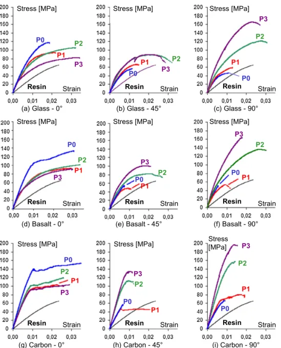
The stress–strain curves are plotted inFig. 7and the mean val-ues of the mechanical properties are given inTable 5. The behav-iour of knit reinforced composites is elastic damageable with various behaviours in the non-linear domain. They exhibit a high behaviour diversity depending on the loading direction, fibrous
Table 4
Tensile properties of the knitted fabrics.
Knitted fabric Fibre type Critical stretched strainec Fabric rigidity (N/mm/mm) Ultimate tensile load Fr (N)
Wale Course Wale Course Wale Course
P0 Glass 0.57 ± 0.02 0.81 ± 0.03 1450 ± 63 443 ± 27 57.2 ± 7.5 18.3 ± 1.9 Basalt 0.59 ± 0.02 0.91 ± 0.01 1573 ± 384 482 ± 71 70.0 ± 8.0 21.5 ± 3.1 Carbon 0.52 ± 0.03 0.88 ± 0.02 2292 ± 351 768 ± 93 111.0 ± 3.0 37.2 ± 3.9 P1 Glass 0.58 ± 0.02 0.19 ± 0.01 1740 ± 138 1917 ± 176 54.0 ± 1.6 90.9 ± 12.0 Basalt 0.54 ± 0.01 0.15 ± 0.01 1866 ± 164 2315 ± 94 57.8 ± 1.9 108.6 ± 5.5 Carbon 0.50 ± 0.01 0.15 ± 0.05 1560 ± 52 2349 ± 366 56.2 ± 1.8 97.4 ± 8.6 P2 Glass 0.54 ± 0.01 0.18 ± 0.01 1525 ± 150 3513 ± 528 52.2 ± 2.6 –a Basalt 0.52 ± 0.02 0.16 ± 0.02 1542 ± 57 2744 ± 177 58.1 ± 3.6 –a Carbon 0.51 ± 0.01 0.16 ± 0.02 1536 ± 74 2422 ± 142 64.1 ± 0.7 –a P3 Glass 0.42 ± 0.03 0.13 ± 0.01 1538 ± 121 3856 ± 269 66.2 ± 3.9 –a Basalt 0.43 ± 0.03 0.09 ± 0.01 1756 ± 165 2902 ± 86 72.0 ± 3.3 –a Carbon 0.47 ± 0.00 0.13 ± 0.01 1370 ± 217 3137 ± 105 71.5 ± 3.8 –a
aAllowable load of the pneumatic grips reached before fabric break.
(a)
(b)
(c)
(d)
(e)
(f)
Plain knit
Plain knit with inlay yarns
Course Wale
Fig. 5. Scheme of a plain-knit fabric and plain-knit with inlay yarns at (a and d) initial state, (b and e) stretched in wale direction and (c and f) stretched in course direction. This figure was drawn using pictures adapted from[29,30].
architecture and fibre type. In all cases the fibre reinforcement in-creases the material elastic modulus when comparing to the net resin sample behaviour. P0 reinforced composites exhibit an aniso-tropic behaviour with higher properties in 0! direction and similar properties in 45! and 90! directions. In this latter direction, the ultimate strength is lower than the net resin strength. The behav-iour of the P0 composites reinforced with basalt and carbon is close to a brittle elastic one, while the P0 composite reinforced with glass fibres, whose properties are the lowest, exhibit a wider non-linear domain before failure (45! and 90!).
Inserting one inlay yarn per course in plain-knit reinforcement has for consequence a slight decrease of the composite properties in the 0! direction attributed to a different arrangement of the fi-bres distribution in the material at similar fibre volume fractions. The insertion of one inlay yarn has no significant effect in the direc-tions 45! and 90!. A slight improvement is obtained with glass fi-bres whereas a small decrease of modulus and strength is observed in the direction 45! with basalt and carbon fibres. Similar properties are obtained in the direction 90! except a wider non-lin-ear domain and a slight increase of strength with carbon fibres.
Indeed, the floated yarns are not straight but curved, limiting a ma-jor orientation of the fibres in the direction 90!, and limiting the expected improvement of the properties in this direction. In addi-tion, a higher porosity is observed in P1 (Table 3).
Increasing the number of inlay yarns per course leads to an important improvement of the properties in the direction 45! and an even larger increase in the direction 90! whereas no signif-icant change is observed in the direction 0!. However, in the load-ing direction 0!, after a loss of properties with the insertion of the first inlay yarn (P1), an increase of the properties is observed with the insertion of the second inlay yarn (P2), attributed to the in-crease of the fibre content, and again a dein-crease in properties is ob-served with the third inlay yarn (P3). In the others loading directions, between P0 and P3, according to the fibre type, an in-crease of 60–105% of the modulus and 61–134% of the ultimate stress is experienced in the testing direction 45!, and an increase of 76–134% of the modulus and 212–288% of the ultimate stress is reached in the loading direction 90!. This is due to a cross-effect of fibre content and fibre distribution. In a general way, the stress– strain curves show that the non-linear domain of composites
(a)
(b)
(c)
(d)
(e)
(f)
Wale-wise
Course-wise
Strain Strain Strain Strain Strain Strain Load per wale [N]Load per wale [N]
Load per wale [N]
Load per course [N]
Load per course [N]
Load per course [N]
Fig. 6. Wale and course direction load versus true strain curves for dry glass, basalt and carbon fibre knitted fabrics. The dotted lines for P2 and P3 knits in the course direction indicate that the failure has not been reached.
(b) Glass - 45°
(c) Glass - 90°
(h) Carbon - 45°
(a) Glass - 0°
(d) Basalt - 0°
(f) Basalt - 90°
Stress [MPa]
Stress [MPa]
Stress
[MPa]
(g) Carbon - 0°
(i) Carbon - 90°
Stress [MPa]
Stress [MPa]
Stress [MPa]
Stress [MPa]
Stress [MPa]
Stress [MPa]
Strain
Strain
Strain
Strain
Strain
Strain
Strain
Strain
Strain
Resin
P0
P1
P2
P3
Resin
Resin
Resin
Resin
Resin
Resin
Resin
Resin
P0
P1
P2
P3
P0
P1
P2
P3
P0
P1
P2
P3
P0
P1
P2
P3
P0
P1
P2
P3
P0
P1
P2
P3
P0
P1
P2
P3
P0
P1
P2
P3
(e) Basalt - 45°
Fig. 7. Representative engineering stress–engineering strain curves of the tensile behaviour of the knit-reinforced composites in the directions 0! (wale), 45! and 90! (course).
Table 5
Tensile properties of the knit reinforced composites.
Fibre type Knitted fabric Longitudinal elastic modulus (GPa) Ultimate stress (MPa)
0! 45! 90! 0! 45! 90! Glass P0 11.2 ± 0.1 8.1 ± 0.2 8.2 ± 0.0 112.2 ± 4.8 54.1 ± 2.2 42.3 ± 3.4 P1 9.8 ± 0.3 9.0 ± 0.4 8.8 ± 0.2 90.7 ± 3.2 66.4 ± 0.2 57.1 ± 3.0 P2 10.8 ± 0.2 11.3 ± 0.3 12.2 ± 0.2 102.8 ± 2.4 86.7 ± 2.1 124.1 ± 5.1 P3 12.1 ± 0.2 13.3 ± 0.4 17.2 ± 0.6 82.4 ± 0.5 87.3 ± 2.7 164.2 ± 1, 2 Basalt P0 12.8 ± 0.1 8.5 ± 0.1 9.3 ± 0.8 136.9 ± 5.4 54.8 ± 0.9 51.1 ± 0.3 P1 9.7 ± 0.4 8.3 ± 0.3 9.0 ± 0.2 84.2 ± 9.2 47.7 ± 1.0 52.5 ± 2.6 P2 10.8 ± 0.2 10.8 ± 0.2 12.0 ± 0.8 97.1 ± 3.7 85.8 ± 4.5 130.0 ± 6.6 P3 11.8 ± 0.3 13.5 ± 0.1 16.4 ± 0.8 87.9 ± 4.6 95.8 ± 6.0 160.9 ± 5.4 Carbon P0 17.5 ± 0.7 8.9 ± 0.0 9.3 ± 0.7 152.1 ± 0.2 55.6 ± 3.2 63.3 ± 3.6 P1 12.7 ± 0.1 8.8 ± 0.2 10.6 ± 1.3 107.9 ± 15 46.0 ± 0.7 75.2 ± 7.6 P2 13.7 ± 0.7 15.0 ± 0.8 19.2 ± 1.4 121.5 ± 4.6 106.6 ± 6.8 163.4 ± 6.3 P3 12.7 ± 0.8 18.2 ± 1.0 21.8 ± 0.2 104.9 ± 3.0 130.2 ± 5.2 197.4 ± 0.0 Resin 3.62 65.5
reinforced by plain-knits with inlay yarns is relatively strong in comparison to P0 reinforced composites. Increasing the number of floated yarns leads to more diffuse damages and to higher strain at break.
The effect of the fibre type depends on the fibrous architecture and the loading direction. In the direction 0! the fibre type effect on the properties decrease is similar irrespective of the fibre types: it is significant for the first inlay yarn whereas a low decrease is no-ticed when increasing the number of inlay yarns. On the contrary, the properties in the directions 45! and 90! are directly related to the number of inlays. In these directions, the more the number of inlay yarns is, the higher the properties of carbon fibres increase, as shown by the increasing gap between the results obtained with carbon fibres and those obtained with glass and basalt fibres. In all cases, best properties are obtained with carbon fibres and this is in agreement with the fibre properties given inTable 1. 4.3. Fracture analysis
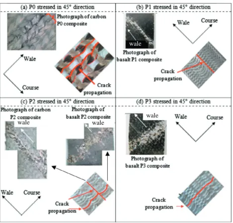
Figs. 8 and 9show photographs and images of cracked speci-mens as well as a schematic view of the fracture surface on the knit samples. In the loading directions 0! and 90! (Fig. 8a and b), the failure occurs systematically in a plane perpendicular to the load-ing direction. For P0 composite specimens tested in the direction 0!, the cracks propagate along a crenel-shape pattern in the vicinity of the fracture (Fig. 8a; ESEM image 1). The crack initiates
perpendicularly to the loading direction by a separation between a fibre tow and the matrix and propagates between a fibre-rich area and a resin-rich area up to the cross-over points. When the crack meet the cross-over area, a bifurcation occurs and the mate-rial damages under shear stresses up to the leg of the stitch. The energy required by this mechanism allow the same phenomenon to take place elsewhere before to go on. At least one crack propa-gates along adjacent stitches until the specimen failure throughout the width of the sample. The two parts of the specimen are then connected by strands of fibres that are then loaded up to the failure (Fig. 8a; SEM image 2). This explains the high strain values reached with P0 composites in the direction 0! in contrast to 45! and 90! (Fig. 7).
When inserting inlay yarns in the reinforcement, the rupture plane remains transverse to the loading direction between the rows of stitches (Fig. 8c). Whatever the fibre type or the number of inlays, the composite damages similarly. The cracks are only lo-cated in the failure area. The cracks initiate between resin-rich and fibre-rich areas and propagate along floated yarns. As for P0 com-posites, the two parts of the specimen are then connected by strands of fibres of the plain knit stitches which are then loaded up to the failure.
In the loading direction 90!, the fracture occurs between resin-rich and fibre-resin-rich areas, by debonding between fibre tows and ma-trix whatever the fibrous architecture (Fig. 8b and d). The cracks follow perfectly the stitches legs of a single wale. The inlay yarns
plays the role of slowing down the cracks propagation by increas-ing the fibre volume fraction perpendicular to the load in this area, which leads to increase the material strength.
In the P0 specimens tested in the direction 45!, the fracture oc-curs in the same way as for those tested in the direction 90! (be-tween a rich and a poor fibre region). A 45! oriented fracture is then obtained (Fig. 9a), and this explains the equivalent properties obtained with P0 composites tested at 45! and 90!. When inserting one inlay yarn, the behaviour is quite similar (Fig. 9b). By inserting two inlay yarns, two cases may arise (Fig. 9c). In the first case, the crack propagation is similar to those of the composites tested in the direction 90! (perpendicular to the inlay yarns,Fig. 8d). This is observed with carbon fibres reinforced composites. In the second case, observed with basalt and glass fibres composites, the crack propagation is similar to the P2 composites tested in the direction 0! (Fig. 8c), i.e. along the floated yarns, leading to a 45! oriented fracture surface occurring along the inlay yarns. This latter failure mode systematically occurs with P3 specimens tested in the direc-tion 45!. With one inlay yarn, the cross-over area is strongly sheared, especially in the tuck stitch area since the floated yarn strengthens the material. With three inlays, the floated yarns con-stitute a continuous unidirectional stripe. High shear strains arise thus in the vicinity of these stripes in areas where the fibres are mainly wale-wise oriented. The failure occurs between these two areas. With two inlays, the tucked wale is not efficiently reinforced by the floated yarns since they are not perfectly parallel to the course (see Fig. 2). Both failure mechanisms are thus possible depending on the fibres properties and on the amount of broken fibres.
5. Conclusion
Insertion of up to three inlays yarns in a plain knit fibre archi-tecture was investigated in order to improve the mechanical
behaviour of knit-reinforced composites. Each knit fabric was man-ufactured with E-glass, basalt and carbon fibres, using the same stitch size and yarn diameter and with a tuck every four wale for the inlaid knits.
The tensile behaviour of each knit in the wale-direction shows that the wale-wise behaviour is not significantly affected by the in-lays, except by modifying the cross-over areas with the tucks. At the contrary, the course-wise direction is significantly reinforced and about five times less deformable with inlay yarns. Indeed, the behaviour of the knit in this case is mainly the behaviour of the inlays. The effect of the fibre type on the behaviour of the knit is negligible compared to the effect of the inlays.
The stress–strain behaviour of the knit reinforced composite material depends on the fibre type but also strongly on the knit construction. Carbon fibres provide the best mechanical properties but the results are not proportional to the intrinsic properties of the fibres when comparing with E-glass and basalt. Inlaying floated yarns does not allow to improve the mechanical behaviour of the composite since it decreases the strength in the direction 0!, but it makes possible to control the anisotropy of the material proper-ties. Highest mechanical properties are reached in the direction 0! for plain-knit reinforced composites, in 90! direction for P3 knitted composites and an almost isotropic material is obtained for the P2 knitted composites.
Acknowledgements
This study was carried out with the financial support of the Re-gion Midi-Pyrénées in the framework of the project CORTEX. The authors would like to thank JTT Composite, and especially MM. Nicolas Dumont and Francis Planel for the design and manufactur-ing of the knits.
wale
wale
wale wale
References
[1]Luo Y, Verpoest I. Biaxial tension and ultimate deformation of knitted fabric reinforcements. Composites Part A 2002;33(2):197–203.
[2]Gommers B, Verpoest I, Van Houtte P. Analysis of knitted fabric reinforced composites: Part 1. Fibre orientation distribution. Composites Part A 1998;29(12):1579–88.
[3]Araújo M, Fangueiro R, Hong H. Modelling and simulation of the mechanical behaviour of weft knitted fabrics for technical applications – Part 1: General considerations and experimental analyses. AUTEX Res J 2003;3(3):111–23. [4]Hagège B, Boisse P, Billoët JL. Finite element analyses of knitted composite
reinforcement at large strain. Euro J Comput Mech 2005;14(6–7):767–76. [5]Lim TC, Ramakrishna S, Shang HM. Optimization of the formability of knitted
fabric composite sheet by means of combined deep drawing and stretch forming. J Mater Proc Technol 1999;89–90:99–103.
[6]Lim TC, Ramakrishna S, Shang HM. Axisymmetric sheet forming of knitted fabric composite by combined stretch forming and deep drawing. Composites Part B 1999;30(5):495–502.
[7]Rozant O, Bourban PE, Manson JAE. Drapability of dry textile fabrics for stampable thermoplastic preforms. Composites Part A 2000;31(11):1167–77. [8]Rozant O, Bourban PE, Manson JAE. Warp-knit laminates for stampable
sandwich preforms. Compos Sci Technol 2001;61(1):145–56.
[9]Khondker OA, Leong KH, Herszberg I, Hamada H. Impact and compression after-impact performance of weft-knitted glass textile composites. Composites Part A 2005;36(5):638–48.
[10]Mouritz AP, Baini C, Herszberg I. Mode I interlaminar fracture toughness properties of advanced textile fibreglass composites. Composites Part A 1999;30(7):859–70.
[11]Falconnet D, Bourban PE, Pandita S, Manson JAE, Verpoest I. Fracture toughness of weft-knitted fabric composites. Composites Part B 2002;33(8):579–88.
[12]Pandita SD, Falconnet D, Verpoest I. Impact properties of weft knitted fabric reinforced composites. Compos Sci Technol 2002;62(7–8):1113–23. [13] Verpoest I, Gommers B, Huysmans G, Ivens J, Luo Y, Pandita S, Philips D. The
potential of knitted fabrics as a reinforcement for composites. In: Proceedings of ICCM-11. Gold Coast, July, 1997. p. 108–33.
[14]Huang ZM, Ramakrishna S. Micromechanical modeling approaches for the stiffness and strength of knitted fabric composites: a review and comparative study. Composites Part A 2000;31(5):479–501.
[15]Leong KH, Falzon PJ, Bannister MK, Herszberg I. An investigation of the mechanical performance of weft-knit milano-rib glass/epoxy composites. Compos Sci Technol 1998;58(2):239–51.
[16]Khondker OA, Herszberg I, Leong KH. An investigation of the structure-property relationship of knitted composites. J Compos Mater 2001;35(6):489–508.
[17]Md Abounaim, Hoffmann G, Diestel O, Cherif C. Development of flat knitted spacer fabrics for composites using hybrid yarns and investigation of two-dimensional mechanical properties. Text Res J 2009;79(7):596–610. [18] Anwar KO, Callus PJ, Leong KH, Curiskis JI, Herszberg I. The effect of
architecture on the mechanical properties of knitted composites. In: Proceedings of ICCM-11. Gold Coast, July, 1997. p. 14–8.
[19]Leong KH, Nguyen M, Herszberg I. The effects of deforming knitted glass fabrics on the basic composite mechanical properties. J Mater Sci 1999;34(10):2377–87.
[20]Khondker OA, Leong KH, Herszberg I. Effects of biaxial deformation of the knitted glass preform on the in-plane mechanical properties of the composite. Composites Part A 2001;32(10):1513–23.
[21] Balea L, Dusserre G, Bernhart G, Dumont N. Mechanical behaviour of technical knitted fabrics for composite applications. In: Comptes rendus des JNC-16. Toulouse, June, 2009.
[22] Dusserre G, Balea L, Ben Salem N, Bernhart G. Influence of knitted reinforcement on the composite mechanical behaviour. In: Proceedings of ACMA-3. Marrakech, May, 2010.
[23] Balea L. Comportement des matériaux composites à renforts tricotés élaborés par injection de résine. PhD thesis, Université de Toulouse, 2011.
[24] Balea L, Dusserre G, Bernhart G, Dumont N. Mechanical behaviour of technical knitted fabrics for composite applications. In: Proceedings of ECCM-14. Budapest, June, 2010.
[25] Balea L, Dusserre G, Bernhart G. Weft-knitted composites: Relationships between fabric architecture, fibre type and mechanical properties of the infused composite. In: Comptes rendus des JNC-17. Poitiers, June, 2011. [26]Leong KH, Ramakrishna S, Huang ZM, Bibo GA. The potential of knitting for
engineering composites – a review. Composites Part A 2000;31(3):197–220. [27]Khondker OA, Fukui T, Nakai A, Hamada H. Initial fracture of the welt
weft-knitted textile composites. Composites Part A 2004;35(10):1185–94. [28]Bueno MA, Renner M, Pac MJ. Influence of properties at micro and mesoscopic
levels on macroscopic level for weft knitted fabrics. J Mater Sci 2002;37(14):2965–74.
[29]Araújo M, Fangueiro R, Hong H. Modelling and simulation of the mechanical behaviour of weft knitted fabrics for technical applications – Part 2: 3D model based on the elastica theory. AUTEX Res J 2003;3(4):166–72.
[30] Bekisli B, Nied HF. Mechanical properties of thermoformed structures with knitted reinforcement. In: Proceedings of RTS 2009. Albi, March, 2009.