HAL Id: tel-01067477
https://tel.archives-ouvertes.fr/tel-01067477
Submitted on 23 Sep 2014
HAL is a multi-disciplinary open access archive for the deposit and dissemination of sci-entific research documents, whether they are pub-lished or not. The documents may come from teaching and research institutions in France or abroad, or from public or private research centers.
L’archive ouverte pluridisciplinaire HAL, est destinée au dépôt et à la diffusion de documents scientifiques de niveau recherche, publiés ou non, émanant des établissements d’enseignement et de recherche français ou étrangers, des laboratoires publics ou privés.
from Signal to C
van Chan Ngô
To cite this version:
van Chan Ngô. Formal verification of a synchronous data-flow compiler : from Signal to C. Software Engineering [cs.SE]. Université Rennes 1, 2014. English. �NNT : 2014REN1S034�. �tel-01067477�
THÈSE / UNIVERSITÉ DE RENNES 1
sous le sceau de l’Université Européenne de Bretagne
pour le grade de
DOCTEUR DE L’UNIVERSITÉ DE RENNES 1
Mention : Informatique
École doctorale Matisse
présentée par
Van Chan NGO
Préparée à l’unité de recherche UMR 6074
Institut National de Recherche en Informatique et en Automatique
Formal Verification of
a Synchronous
Data-flow Compiler : from
Signal to C
Thèse soutenue à Rennes le 01 Juillet 2014
devant le jury composé de :
Sandrine BLAZY
Professeur à l’Université de Rennes/ présidente
Jean-Paul BODEVEIX
Professeur à l’Université de Toulouse / rapporteur
Laure GONNORD
Maître de Conférence, Université de Lyon /
rapportrice
Abdoulaye GAMATIÉ
Chargé de Recherche, CNRS-LIRMM / examinateur
Dumitru POTOP-BUTUCARU
Chargé de Recherche, INRIA Rocquencourt /
examinateur
Jean-Pierre TALPIN
Directeur de Recherche, INRIA Rennes / directeur
I would like to express my gratitude to my advisor, Jean-Pierre Talpin. Thanks for all his support, my three years of Ph.D. have been a very useful time. I learnt much from his experience and knowledge. He has been a great advisor. He gave me the freedom of pursing my goals and interests while always providing guidance. Thank you so much Jean-Pierre.
I would like to thank the members of my Ph.D. committee, specially Jean-Paul Bodeveix and Laure Gonnord who agreed on reviewing my dissertation and gave useful and interesting comments.
I also would like to thank my colleagues Loïc Besnard, Thierry Gautier, Paul Le Guer-nic, Huafeng Yu, Yue Ma, Christophe Junke, Adnan Bouakaz, Sun Ke in the TEA group
at INRIA, Abdoulaye Gamatié and Sandeep Shukla for their friendship and support. My
special thanks to Thierry and Abdoulaye who has read and commented on every bit of my reports and this dissertation, and who has listened to every idea I had during my time at INRIA.
I also would like to thanks my friends here, in RENNESfor their help and relaxed time. Last but not least, I would like to thank my family, especially my parents, Van Tac & Ngo Ngo who have always been there for me. Only I know that this dissertation cannot be carried out without them.
Synchronous languages such as SIGNAL, LUSTREand ESTERELare dedicated to designing
safety-critical systems. Their compilers are large and complicated programs that may be incorrect in some contexts, which might produce silently bad compiled code when com-piling source programs. The bad compiled code can invalidate the safety properties that are guaranteed on the source programs by applying formal methods. Adopting the transla-tion validatransla-tion approach, this thesis aims at formally proving the correctness of the highly optimizing and industrial SIGNAL compiler. The correctness proof represents both source program and compiled code in a common semantic framework, then formalizes a relation between the source program and its compiled code to express that the semantics of the source program are preserved in the compiled code.
Les langages synchrones tels que SIGNAL, LUSTREet ESTERELsont dédiés à la conception de systèmes critiques. Leurs compilateurs, qui sont de très gros programmes complexes, peuvent a priori se révéler incorrects dans certains situations, ce qui donnerait lieu alors à des résultats de compilation erronés non détectés. Ces codes fautifs peuvent invalider des propriétés de sûreté qui ont été prouvées en appliquant des méthodes formelles sur les pro-grammes sources. En adoptant une approche de validation de la traduction, cette thèse vise à prouver formellement la correction d’un compilateur optimisé et industriel de SIGNAL. La
preuve de correction représente dans un cadre sémantique commun le programme source et le code compilé, et formalise une relation entre eux pour exprimer la préservation des sémantiques du programme source dans le code compilé.
Contents vii
Listings xi
List of Figures xiii
List of Tables xv
1 Introduction 1
1.1 Correctness of compilation . . . 2
1.2 Formal compiler verification . . . 5
1.3 Translation validation . . . 7
1.4 Contributions . . . 9
1.4.1 Preservation of clock semantics . . . 11
1.4.2 Preservation of data dependency . . . 12
1.4.3 Preservation of value-equivalence of variables . . . 13
1.4.4 Towards a formally verified SIGNALcompiler . . . 13
1.5 Chapter plan . . . 14
2 Related work in compiler verification 16 2.1 Compiler verification based on testing . . . 18
2.2 Compiler verification based on formal methods . . . 20
3 Synchronous data-flow languages 26 3.1 Embedded, reactive and real-time systems . . . 26
3.1.1 Reactive systems . . . 27
3.1.2 Real-time systems . . . 28
3.2.1 Classical approaches . . . 30
3.2.2 The synchronous approach . . . 31
3.3 The SIGNALlanguage . . . 31
3.3.1 Synchronized data flow . . . 31
3.3.2 An overview of the language . . . 32
3.3.3 Semantics of the language . . . 36
4 Translation validation of transformations on clocks 44 4.1 The clock calculus in SIGNALcompiler . . . 45
4.2 The synchronization spaceZ/3Z . . . 47
4.2.1 PDSmodel . . . 49
4.3 Translation validation of PDSs . . . 53
4.3.1 Definition of correct transformation: PDSrefinement . . . 53
4.3.2 Proving refinement by simulation . . . 56
4.3.3 Composition of compilation phases . . . 58
4.3.4 Implementation with SIGALI . . . 59
4.4 Translation validation of clock models . . . 63
4.4.1 Clock model of SIGNALprogram . . . 63
4.4.2 Soundness of clock model . . . 69
4.4.3 Definition of correct transformation: Clock refinement . . . 74
4.4.4 Proving clock refinement by SMT . . . 76
4.4.5 Implementation with SMT . . . 78
4.4.6 Detected bugs . . . 83
4.5 Discussion . . . 84
5 Translation validation of SDDG 86 5.1 The data dependency analysis in SIGNALcompiler . . . 87
5.2 Synchronous data-flow dependency graph . . . 89
5.2.1 Data dependency graphs . . . 90
5.2.2 SIGNALprogram as synchronous data-flow dependency graph . . . 90
5.3 Translation validation of SDDG . . . 94
5.3.1 Definition of correct implementation: Dependency refinement . . . 94
5.3.2 Adaptation to the SIGNALcompiler . . . 98
5.3.3 Proving dependency refinement by SMT . . . 99
5.3.4 Implementation . . . 100
5.4.1 Deadlock detection in the SIGNALcompiler . . . 103
5.4.2 A more precise deadlock detection . . . 105
5.4.3 Precise deadlock detection . . . 110
5.5 Discussion . . . 113
6 Evaluating SDVGtranslation validation: from SIGNALto C 115 6.1 Code generation in SIGNALcompiler . . . 116
6.1.1 The principle . . . 116
6.1.2 Sequential code generation . . . 119
6.2 Illustrative example . . . 120
6.3 Synchronous data-flow value-graph . . . 123
6.3.1 Definition of SDVG . . . 125
6.3.2 SDVGof SIGNALprograms . . . 130
6.3.3 SDVGof generated C code . . . 138
6.4 SDVGtranslation validation . . . 143
6.4.1 An introduction to graph rewriting . . . 143
6.4.2 Normalizing . . . 148
6.4.3 Implementation . . . 157
6.5 Discussion . . . 161
7 Conclusion 163 7.1 Summary of the contribution . . . 163
7.2 Future work . . . 165
1.1 Bug 15549 . . . 2
1.2 Stack-machine code of(x + 2) ∗ y . . . 4
1.3 Pseudo-code implementation of formal verified SIGNALcompiler . . . 14
2.1 Bit clear test case with SUPERTEST . . . 19
3.1 “Event driven” . . . 29
3.2 “Sampling” . . . 29
3.3 DEC in Signal . . . 35
4.1 ALTERN in Signal . . . 52
4.2 PDSof ALTERN . . . 53
4.3 Compute symbolic simulation . . . 60
4.4 Symbolic simulation implementation in SIGALI . . . 61
4.5 DEC_BASIC_TRA in Signal . . . 80
5.1 DEC_SEQ_TRA in Signal . . . 101
5.2 CycleDependency in SIGNAL. . . 104
6.1 Structure of P_main.c . . . 117
6.2 Structure of P_io.c . . . 118
6.3 Program WHENOP in SIGNAL . . . 120
6.4 Synchronous Step of WHENOP . . . 120
6.5 Simple Program in SIGNAL . . . 131
6.6 SDVGMerge in SIGNAL . . . 140
6.7 Generated C code of SDVGMerge . . . 140
6.8 Normalizing value-graph . . . 148
6.9 MasterClk in SIGNAL . . . 154
6.10 Generated C code of MasterClk . . . 154
1.1 The compilation process of a synchronous compiler . . . 1
1.2 Phases of compiler design . . . 3
1.3 A bird’s-eye view of translation validation framework . . . 8
1.4 The compilation process of the SIGNALcompiler . . . 9
1.5 The translation validation for the SIGNALcompiler . . . 11
4.1 A bird’s-eye view of the verification process . . . 45
4.2 The PDStranslation validation . . . 60
4.3 Rule CLKREF . . . 76
4.4 The clock model translation validation . . . 79
5.1 Translation validation of SDDG . . . 87
5.2 The GCDof DEC . . . 89
5.3 CFG for Sum, with data dependency edges for i (dotted lines) . . . 91
5.4 The SDDGof merge operator . . . 91
5.5 The SDDGof DEC . . . 94
5.6 A bird’s-eye view of the SDDGtranslation validation . . . 101
5.7 The SDDGof DEC_SEQ_TRA . . . 102
5.8 Dependencies among y, u, v . . . 105
5.9 The SDDG+of CycleDependency . . . 109
5.10 An overview of our approach . . . 111
6.1 A bird’s-eye view of the verification process . . . 116
6.2 Code generation: General scheme . . . 117
6.3 The shared value-graph of WHENOP and WHENOP_step . . . 123
6.4 The resulting transformed value-graph . . . 124
6.5 The final value-graph . . . 124
6.7 The subgraph rooted at node labeled+ and a root-cyclic graph . . . 127
6.8 An example of homomorphism . . . 128
6.9 The subgraphs of y := x ∗ x1 and x1 := x + 1 . . . 131
6.10 The SDVGgraph of P . . . 132
6.11 The graph of y := f (x1, ..., xn) . . . 132
6.12 The graph of y := (x >= 1) and c . . . 133
6.13 The graph of y := x$1 init a . . . 134
6.14 The graph of y := (x$1 init 1) + z . . . 134
6.15 The graph of y := x default z . . . 135
6.16 The graph of y := x default (z + 1) . . . 135
6.17 The graph of y := x when b . . . 136
6.18 The graph of y := x when (z >= 1) . . . 137
6.19 The graphs of (1) z :=ˆx, (2) xˆ= y and (3) z := xˆ+ y . . . 137
6.20 The graphs of (4) z := xˆ∗ y, (5) z := xˆ− y and (6) z := when b . . . 138
6.21 The graph of SDVGMerge_step . . . 141
6.22 The graph of N’s computation . . . 142
6.23 The transformation of the graph of t ∗(u + 1) . . . 144
6.24 The transformation of graph of t ∗(u + 1) with sharing of repeated subterms 144 6.25 The graph rule of the term rule φ(c, x, f alse) → c ∧ x . . . 146
6.26 An example of graph rewriting . . . 147
6.27 Graph rewriting: Build and redirection phases . . . 147
6.28 Graph rewriting: Garbage collection phases . . . 148
6.29 The shared value-graph of MasterClk and MasterClk_step . . . 155
6.30 The resulting graph of MasterClk and MasterClk_step by applying the rule 6.38 . . . 156
6.31 The resulting graph of MasterClk and MasterClk_step by applying the rule 6.39 . . . 156
6.32 The final normalized graph of MasterClk and MasterClk_step . . . 157
6.33 A bird’s-eye view of the SDVGtranslation validation . . . 158
6.34 The shared value-graph of DEC and DEC_step . . . 159
6.35 The resulting value-graph of DEC and DEC_step . . . 160
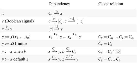
3.1 The implicit clock relations and dependencies . . . 34
4.1 Translation validation of PDSs: Experimental results . . . 64
4.2 Clock semantics of the SIGNALprimitive operators . . . 71
5.1 The implicit dependencies and their encoding in GCD . . . 88
I
NTRODUCTION
Synchronous programming languages such as SIGNAL, LUSTRE and ESTEREL propose a
formal semantic framework to give high-level specification of safety-critical software in automotive and avionics systems [17, 71, 73, 81]. As other programming languages, syn-chronous languages are associated with a compiler. The compiler takes a source program, analyses and transforms it, performs optimizations, and finally generates executable code in a general-purpose programming language (e.g., C, C++, or JAVA). This compilation process is depicted as in Figure1.1.
Synchronous Program Transformed Program Executable Code (C, Java) Verification Guarantees? Verification Guarantees equivalence? Verification Guarantees? equivalence?
Fig. 1.1 The compilation process of a synchronous compiler
Safety-critical systems are those systems whose failure could result in loss of life, or damage to the environment. Safety-critical systems need to be validated to ensure that their specified safety properties are implemented correctly. Software validation is traditionally done by using testing techniques which, in the case of safety-critical systems, is not suffi-cient [102]. The validation of safety-critical systems needs to be complemented by the use of formal verification, such as static analysis, model checking, or proof, to guarantee full coverage of the safety requirements on the validated system.
Since synchronous languages are based on strong semantic models, they provide much higher level of abstraction, expressivity, and clarity at source level rather than once compiled into C code. That makes the application of formal methods much simpler to enforce safety properties.
However, a compiler is a large and very complex program which often consists of hun-dreds of thousands, if not millions, lines of code, divided into multiple sub-systems and modules. Moreover, compiler modules often interact in very complex ways, and the design and implementation of a compiler is a substantial engineering task. The compilation process involves many analyzes, program transformations and optimizations. Some transformations and optimizations may introduce additional information, or constrain the compiled pro-gram. They may refine its meaning and specialize its behavior to meet a specific safety or optimization goal.
Consequently, it is not uncommon that compilers silently issue an incorrect result in some unexpected context or inappropriate optimization goal. For example, the GNU
Com-piler Collection (GCC) is a compiler produced by GNUProject supporting several languages. GCC has been widely used in software development. It is also available for most embed-ded platforms. Although it has a long history of development and review by many people, no programmer can assert that it is always right in any context; see the list of bugs which have been found at GCCBugzilla [121]. Considering bug number 15549, for instance, GCC
will compile the expression b< c as (b == 0)&(c! = 0) into the following program, which always aborts. Listing 1.1 Bug 15549 1 int lt ( _ B o o l b , u n s i g n e d c h a r c ) { 2 r e t u r n b < c ; 3 } 4 5 int m a i n () { 6 if (! lt (1 , ’ a ’ ) 7 a b o r t () ; 8 }
An incorrectly compiled program like the one above will most likely invalidate the safety properties that were secured on the source program. Yet, it is natural to require a compiler to guarantee the preservation of the source program’s semantics, hence the safety properties are secured on it.
1.1
Correctness of compilation
Proving the correctness of a compiler can be based on the examination of the developed compiler’s source code itself, meaning that a qualification process applies on the
develop-ment of the compiler, the source of the compiler, and/or the compiler’s output. Qualifying a compiler is rare because of the tremendous administrative effort involved. Qualification amounts to demonstrate compliance with all recommendations and objectives specified in the certification standards for safety-critical softwares: DO-178C and its European equiv-alent ED-12 [49]. Although DO-178 has been successful in industry, the cost of comply-ing with it is significant: the activities on verification it incurs may well cost seven times more than the development effort needed [126]. A more traditional method is therefore to solely inspect or formally verify the compiler’s output. This task requires less unitary effort, but has to be repeated every time a new target code is generated. For instance, the work of Blanchet et al. [23, 24] provides a method to design and implement a special-purpose abstract interpretation based static program analyzer for the verification of safety critical embedded real-time software. And the static program analyzer ASTRÉE[9] aims at proving
the absence of run time errors (RTE) in the generated C code of the synchronous data-flow compiler from LUSTREprograms. One last resort is hence to formally verify the correctness of the compiler itself.
A compiler is a computer program that reads an input program in one source language and translates it into a semantically equivalent refined program in another target language, Figure1.2. The structure of a compiler consists of two parts:
Analysis The analysis part creates an intermediate representation of the source program and stores information about the source program in a data structure, the symbol table. Synthesis The synthesis part generates the desired output program from the intermediate representation and information stored in the symbol table.
We usually call the analysis part the front end of the compiler, and the synthesis part its back end.
Lexical Analysis Syntax Analysis Semantic Analysis
Intermediate Code Optimization Code Generation Source
Language
Target Language
Fig. 1.2 Phases of compiler design
executed, e.g., its pre and post-conditions. It may describe interactions and relationships among program components (e.g., program variables, functions,...). The program is said to be correct with respect to its inputs and outputs if for all program executions with inputs satisfying the required specification. This definition applies for a compiler as well. There are two fundamental principles in design and implementation of a compiler which have to be fulfilled [41]:
The compiler must preserve the meaning of the program being compiled. The compiler must improve the input program in some discernible way. For example, consider the compilation of an arithmetic expression, onto a stack-machine, in the form of one address code. Compilation assumes the presence of a stack of operands. Operations pop operands from the stack, evaluate them and push the result back onto the stack. For instance, an integer multiplication takes the top two elements from the stack and pushes their product onto the stack. Stack-machine code of the expression(x + 2) ∗ y would be as follows:
Listing 1.2 Stack-machine code of(x + 2) ∗ y
1 p u s h x 2 p u s h 2 3 add 4 p u s h y 5 m u l t i p l y
In order to prove the correctness of this compilation, one can develop an interpreter that feeds test operations and parameters to the compiler and interprets the source and compiled program to check output equality. For the stack-machine code generation, evaluating a source expression with test inputs should yield the same result as the value on top of the stack in the interpreted address code.
In this line of research, Sheridan’s paper [128] is a good survey on compiler testing. ACE
[2] provides the SUPERTESTcompiler test and validation suite which is a large collection of
self-testing programs. The certifying compilation [104] attests that the generated object code satisfies the properties established on the source program by generating concrete evidences along the compilation into object code.
Systematic compiler verification techniques use formal methods. Formal methods advo-cate the use of a mathematical framework for the specification, development and verification of software and hardware systems. For the purpose of compiler verification, there are two approaches, in general, to prove the software correctness:
Formal compiler verification Specifying the intended behavior of the compiler in a for-mal specification language and building a proof that the compiler satisfies behavioral equiv-alence or refinement.
Translation validation Proving that each run of the compiler preserves the semantics of the source program in the generated code.
We shall discuss these two approaches in Section1.2 and Section 1.3, and their appli-cation to the translation validation to a multi-clocked synchronous data-flow compiler in Section1.4.
1.2
Formal compiler verification
In the context of software systems, formal verification is a problem of proving the cor-rectness of a system with respect to the desired properties, using formal methods. The verification process consists of constructing an abstract mathematical model of the system behavior and of providing a formal proof on that model. There are several mathematical objects which may be used to construct the abstract model of a system, such as finite state machines, labeled transition systems, Petri nets, automaton, process algebra, and formal semantics of programming languages.
Formal verification can be done though many approaches. One such approach is deduc-tiveverification. It consists of providing deductive proofs that a system behaves in a certain way that is described in the specification, with the aid of either interactive theorem provers (such as HOL [33, 69], ISABELLE [78], or COQ [42]), or an automated theorem prover. It often requires to have knowledge of the system mechanism and why the system works correctly, and then convey this information to the verification process.
Another approach is model checking [37–39,123]. It involves building an abstract model of the system and ensure that the system model complies with specified requirements by ex-ploring all its accessible states. The system to be verified is often represented in temporal logics, such as Linear Temporal Logic (LTL) or Computational Tree Logic (CTL). The veri-fication process produces a confirmation that the system model conforms to requirements or a counterexample that can be used to locate and eliminate an error. The main disadvantage of this approach is that it does not in general scale to large systems due to the state explo-sionproblem. Some techniques must be used to deal with this problem including abstract interpretation, symbolic simulation and abstract refinement [43–45].
propositional satisfiability problems (or SAT). Bounded model checking (BMC) [20, 36]
encodes the fact that potential executions of the system model do not conform to the specifi-cation in incremental fashion as propositional satisfiability formulas. The bounded number of evaluation steps is increased as long as the resulting propositional formula is satisfiable. Then a concrete counterexample can be extracted as a trace of system states leading to an error state in the system model.
Another approach is to use inductive reasoning to prove that a system conforms to its specification. The advances in solvers based on Satisfiability Modulo Theories (SMT) have been useful in checking systems inductively. With these solvers, systems can be modeled ef-ficiently, require fewer limitation on representation of the specifications, while still meeting significant performance. In inductive approach, the transition relation of system a property are encoded as logic formulas. Then, it checks that the property is satisfied at initial state as the base case. If the base case holds true, take the assumption that the property holds for some state and prove that it holds for next state as well.
As usual, formal compiler verification is the problem of proving that the behavior of a compiler meets certain specifications. For instance, a compiler of arithmetic expressions for stack machines has to verify that the result of an evaluated operation is the same as that on top of the machine code’s stack after execution. A formal compiler verification con-sists of establishing the given correctness property between source program and its com-piled program. In our case, a correctness property should be that, if a source program has well-defined semantics, then it should be observationally equivalent to its generated code. Establishing this correctness property usually consists of:
• Specifying the intended behavior of a compiler in a specification language. This lan-guage is defined deterministically based on formal, deductive logic. The specification of the compiler is expressed in terms of the representation of the source and the com-piled programs.
• Building a proof, based on some mathematical reasoning and automated proving tech-niques, to show that the compiler satisfies its model of intended behavior.
Given a source program A, the compilation of a compiler can be considered as a function C p from a set of source programs to the set of compiled programs and the compilation error: Ps−→ Pc∪ {Error}. We denote the compiled program of A by Cp(A) = C and the compilation error by C p(A) = Error. In other words, for every source program, the output of the compilation is either a compiled program or an error. Then the semantic equivalence between the compiled program and the source program is ensured by the correctness of the
compiler. Following the above conception of formal compiler verification, a compiler is a formally verified compiler if it is accompanied with a formal proof of the following theorem [92].
∀A ∈ Ps,C ∈ Pc, Cp(A) = C ⇒ Correct(A,C) (1.1)
where Correct(A,C) denotes the correctness property between the source program A and its compiled program C.
Therefore, formal compiler verification formally ensures the correctness of the com-piler. It makes sure that all guarantees obtained on the source program are preserved in the compiled program. This is particularly important if the compiler is used in development of safety-critical embedded systems, since the safety requirements for the development tools (e.g., compilers, translators,...) that translate programs are very high and require the most rigorous verification methods.
1.3
Translation validation
In the translation validation approach, the compiler is not verified. Instead, a validator is associated with the compiler to verify the correctness of each run of the compiler.
The notion of translation validation was first introduced by Pnueli et al. in [118] as an approach to verify the correctness of translators (compilers, code generators). The main idea of translation validation is that instead of proving the correctness of the translator, each indi-vidual translation (e.g., run of the code generator) is followed by a validation process which checks that the target program correctly implements the source program. It first constructs the formal models of both the source and compiled programs capturing their semantics. Then, it tries to establish a refinement relation between the formal models of the source and target program. If the compiled program behaves differently than the source program then one cannot establish that relation. Fortunately, the compilation scenario should provide a counter-example to help correcting the compiler error.
A verification framework which adopts translation validation benefits from the following features:
• The verification framework does not modify or instrument the compiler. It treats the compiler as a “black box” (as long as there is no error in it). It only considers the input program and its compiled result. Hence, it is not affected by updates and modifications to the compiler, as long as its data-structures remain the same.
• In general, the validator is much simpler and smaller than the compiler. Thus, the proof of correctness of the validator takes less effort than the proof of the compiler. • The verification process is fully automated.
• The validator can be scaled to large programs, in which we represent the desired pro-gram semantics with our scalable abstraction and use efficient techniques to achieve the expected goals: traceability and formal evidence.
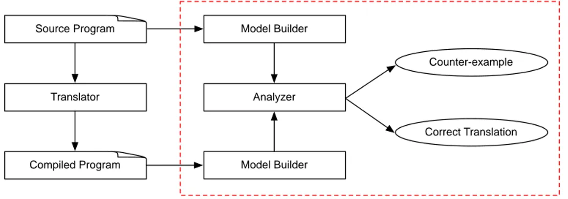
A verification framework which adopts the translation validation approach consists of the components depicted in Figure1.3.
Model builder The model builder defines a common semantic representation to capture the semantics of the source program and the compiled program of the translator. The outputs of this module are the formal models of these programs (e.g., they can be a kind of labeled transition system, or a first-order logic formula).
Analyzer The analyzer first formalizes the notion of "correct implementation" as a refine-ment relation. This relation expresses that the semantics of the source program is preserved during the compilation. This relation is defined based on the common semantic represen-tation of the model builder. The analyzer also provides an automated proof method which allows to prove the existence of the refinement between the formal models. If the analyzer successfully proves the existence of the refinement, a proof script will be created. Other-wise, it will generate a counter-example.
Translator Source Program Compiled Program Model Builder Model Builder Analyzer Counter-example Correct Translation
Fig. 1.3 A bird’s-eye view of translation validation framework
For example, in the work of Pnueli et al., the semantics of the source program and its compiled program are represented as Synchronous Transition Systems (STS). That is the
common semantic framework. Given two STSs, they formalize the concept of “correct
translation” as a refinement relation for them which expresses that the semantics of the source program is preserved in the compiled program. The refinement is checked by the use of a solver and the proof script is also generated.
1.4
Contributions
Considering the compiler of the synchronous data-flow language SIGNAL, the compilation process can be divided into three phases as depicted in Figure1.4. It consists of a sequence of code transformations and optimizations. Some transformations are optimizations that rewrite the code to eliminate inefficient expressions. The transformations may be seen as a sequence of morphisms rewriting SIGNALprograms to SIGNALprograms, meaning that
the intermediate representations produced by the compiler are written in SIGNAL. The final steps, C or JAVA code generation, are simple morphisms over the ultimately transformed program.
Clock calculation and Boolean abstraction Calculates the clock of all signals in the program and defines a Boolean abstraction of the program. The clock of a signal defines exactly when a signal shall be evaluated in a program. The intermediate representation of this phase is written in SIGNALlanguage.
Static scheduling Based on the clock information and the Boolean abstraction obtained at the first stage, the compiler constructs the Conditional Dependency Graph (CDG) to rep-resent the static schedule of all signals’ evaluation.
Code generation The clocked and scheduled Signal program is ready to directly generate executable code (e.g., sequential code in C or JAVA).
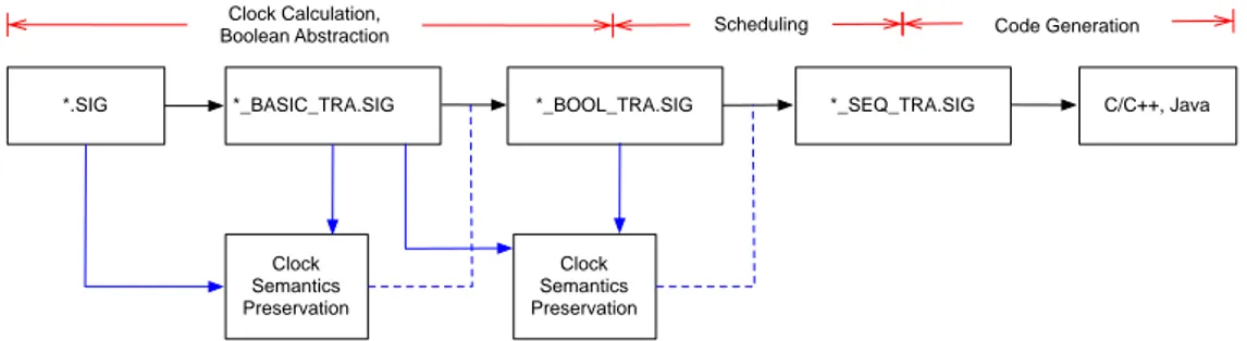
*.SIG *_BASIC_TRA.SIG *_BOOL_TRA.SIG *_SEQ_TRA.SIG C/C++, Java Clock Calculation,
Boolean Abstraction Scheduling Code Generation
Fig. 1.4 The compilation process of the SIGNALcompiler
As a contribution to this dissertation, we evaluate the concept of translation validation and study the way to adopt it to prove the correctness of the SIGNAL compiler. We also
show that it is possible to construct a validator that is plugged to the compiler in such a way it can provide formal correctness guarantees comparatively strong to these which could be obtained by proof assisted formal compiler verification.
Write C to denote the compiled program and Error to denote the compilation error of a source program A. Consider a validator Val which adopts the translation validation approach. The validator can be represented as a function from the set of pairs of a source program and its compiled program to the set of Boolean values: Ps× Pc−→ B. The validator that we want to build satisfies the following property:
∀A ∈ Ps,C ∈ Pc,Cp(A) = C,Val(A,C) = true ⇒ Correct(A,C) (1.2)
We now associate each run of the compiler C p with the validator Val. The following func-tion C pValdefines a formally verified compilation process from Psto Pcand the compilation error. C pVal(A) =
C if C p(A) = C and Val(A,C) = true
Error if C p(A) = C and Val(A,C) = false Error if C p(A) = Error
The verification of the derived compiler C pVal reduces to the verification of the associated validator Val, meaning that the compiler does not need to be verified and can be consid-ered as a black box. The following trivial theorem is the base of our line of work in this dissertation.
Theorem 1 If the validator Val satisfies the property1.2, then the derived compiler C pVal is formally verified in the sense of Theorem1.1.
It is obvious to prove globally that the source program and its final compiled program have the same semantics. However, we believe that a better approach is to separate concerns and prove each analysis and transformation stage separately with respect to ad-hoc data-structures to carry the semantic information relevant to that phase.
In the case of the SIGNAL compiler, the preservation of the semantics can be decom-posed into the preservation of clock semantics at the clock calculation phase and that of data dependencies at the static scheduling phase, and, finally, value-equivalence of variables at the code generation phase.
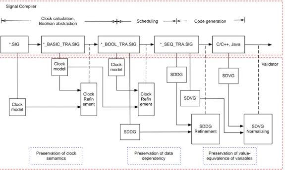
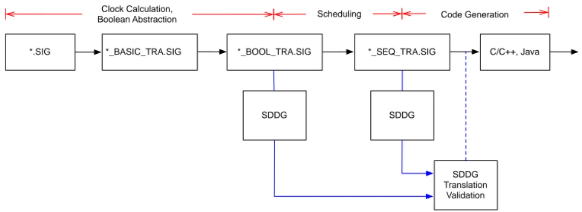
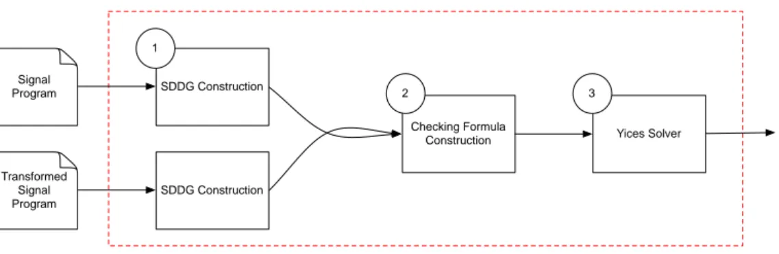
Figure 1.5 shows the integration of this verification framework into the compilation process of the SIGNALcompiler. For each phase, the validator takes the source program and its compiled counterpart, and constructs the corresponding formal models of the programs.
Then, it checks the existence of the refinement relation to prove the preservation of the considered semantics. If the result is that the relation does not exist then a “compiler bug” message is emitted. Otherwise, the compiler continues its work.
*.SIG *_BASIC_TRA.SIG *_BOOL_TRA.SIG *_SEQ_TRA.SIG C/C++, Java Clock calculation,
Boolean abstraction Scheduling Code generation
Clock model Clock model Clock Refin ement Clock Refin ement Clock model Signal Compiler Validator SDDG SDDG SDDG Refinement SDVG SDVG SDVG Normalizing Preservation of clock semantics Preservation of data dependency Preservation of value-equivalence of variables
Fig. 1.5 The translation validation for the SIGNALcompiler
1.4.1
Preservation of clock semantics
The first verification stage focuses on proving that all clock relations associated with sig-nalsin the source and transformed program are equivalent. We propose two approaches to implement this verification, one based on model checking and the other on SMTsolving.
In the first approach, the clock semantics of the source and transformed programs are represented by Polynomial Dynamical Systems (PDSs). A PDS is a system of equations,
in which the coefficients of equations range over Z/3Z. The notion of “correct imple-mentation” is formalized as a PDS refinement. An automated proof method based on the
simulation technique is provided for checking the existence of this refinement.
In the second approach, the clock semantics of the source and transformed programs are formally represented as clock models. A clock model is a first-order logic formula that characterizes the presence/absence status of all signals in a SIGNALprogram at a given in-stant. Given two clock models, a clock refinement between them is defined which expresses the semantic preservation of clock semantics. A method to check the existence of clock
refinement is defined as a satisfiability problem which can be automatically and efficiently proved by an SMTsolver.
Let C psig and Valclk be the functions which define the SIGNALcompiler and a valida-tor, respectively. The following function defines a formally verified compiler for the clock calculation and Boolean abstractionphase. We write C ⊑clk Ato denote that there exists a refinement between A and C.
C psigVal clk(A) =
C if C psig(A) = C and Valclk(A,C) = true Error if C psig(A) = C and Valclk(A,C) = false Error if C psig(A) = Error
where Valclk(A,C) = true if and only if C ⊑clk A.
1.4.2
Preservation of data dependency
Given two signals in a source program, the aim of this work is to prove that data dependenies between them are preserved in the scheduled program. This verification also ensures that if there is no deadlock in the source program, then there is no deadlocks in the scheduled one either.
In order to do that, the data dependencies among signals are represented by a common semantic framework, called Synchronous Data-flow Dependency Graph (SDDG). A SDDG
is a labeled directed graph, in which each node is a signal or a clock and each edge represents the dependency between nodes. Each edge is labeled by a clock expression called clock constraintat which the dependency between two extremity nodes is effective. The notion of “correct implementation” is formalized as a dependency refinement relation between graphs. This relation expresses the semantic preservation of data dependencies. It is implemented using an SMTsolver to check the existence of the refinement relation.
Let Valdep be the function which defines a validator. The following function defines a formally verified compiler for the static scheduling phase of the SIGNAL compiler. We denote the fact that C refines A by C ⊑depA.
C psigVal dep(A) =
C if C psig(A) = C and Valdep(A,C) = true Error if C psig(A) = C and Valdep(A,C) = false Error if C psig(A) = Error
1.4.3
Preservation of value-equivalence of variables
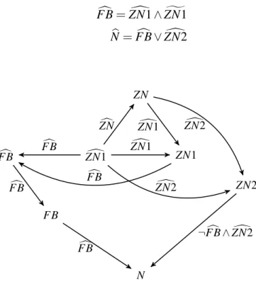
This work focuses on proving that every output signal in the source program and the corre-sponding variable in the compiled program, the generated C program, have the same values. The computations of all signals and their compiled counterparts are represented by a shared value-graph, called Synchronous Data-flow Value-Graph (SDVG).
Given a SDVG, assume that we want to show that two variables have the same value. We simply need to check that they are represented by the same sub-graph, meaning that they point to the same graph node. If all output signals in the source program A and the corresponding variables in the generated C program have the same value, then we say that Crefines A, denoted by C ⊑val A.
Let Valval be the function which defines a validator. The following function defines a formally verified compiler for the code generation phase.
C pValsig val(A) =
C if C psig(A) = C and Valval(A,C) = true Error if C psig(A) = C and Valval(A,C) = false Error if C psig(A) = Error
where Valval(A,C) = true if and only if C ⊑val A.
1.4.4
Towards a formally verified S
IGNALcompiler
The derived SIGNALcompiler that is associated by the validator, denoted by Val, in Figure
1.5can be defined by the following function from Ps to Pcand the compilation error.
C pValsig(A) =
C if C psig(A) = Cclk,Cpsig(Cclk) = Cdep,Cpsig(Cdep) = C and Val(A,C) = true
Error if C psig(A) = Cclk,Cpsig(Cclk) = Cdep,Cpsig(Cdep) = C and Val(A,C) = false
Error if C psig(A) = Error or Cpsig(Cclk) = Error or C psig(Cdep) = Error
Cclk and Cdep are the intermediate forms of the source program A as the outputs of the clock calculation and Boolean abstractionand static scheduling phases. C is the generated C program from the intermediate form Cdep. Val(A,C) = true if and only if Cclk ⊑clk
A,Cdep ⊑depCclk and C ⊑val Cdep. The pseudo-code implementation of the function above is given in Listing1.3.
Listing 1.3 Pseudo-code implementation of formal verified SIGNALcompiler 1 if (C psig(A) == Error ) r e t u r n E r r o r ;
2 e l s e 3 { 4 if (Cclk⊑clkA) 5 { 6 if (C psig(Cclk) == Error ) r e t u r n E r r o r ; 7 e l s e 8 { 9 if (Cdep⊑depCclk) 10 {
11 if (C psig(Cdep) == Error ) r e t u r n E r r o r ;
12 e l s e 13 { 14 if (C ⊑valCdep) r e t u r n C; 15 e l s e r e t u r n E r r o r ; 16 } 17 } 18 e l se r e t u r n E r r o r ; 19 } 20 } 21 e l s e r e t u r n E r r o r ; 22 }
1.5
Chapter plan
In the remainder of this dissertation, the chapter structure is as follows:
• Chapter2 surveys related works in the field of verification of the correctness of the compilation process.
• Chapter3introduces the concept of synchronous programming. We study the SIGNAL
language as an instance of multi-clocked synchronous data-flow languages used to describe reactive systems, specially safety-critical systems.
• Chapter4presents our methods of proving the preservation of clock semantics when the SIGNAL compiler calculates the clock information and makes the Boolean ab-straction.
• Chapter 5 provides a method to prove the preservation of data dependencies. We define the common semantic frameworks to capture the data dependencies among variables in the programs, called Synchronous Data-flow Dependency Graph. Given the formal representations of data dependencies, we formalize the notion of “correct implementation” as a refinement relation between graphs.
• Chapter6presents a method based on the translation validation approach to prove the preservation of value-equivalence of variables between a source SIGNALprogram and its generated C code. The computation of variables in the programs is represented as a Synchronous Data-flow Value-Graph. Value-equivalence of variables is validated by the normalization of graphs.
2
R
ELATED WORK IN COMPILER VERIFICATION
The story of compiler verification began in 1967 with Mc.Carthy and Painter [99] present-ing the correctness proof for an algorithm compilpresent-ing arithmetic expressions into machine language, and then with Milner’s mechanized logical proof of a compiler in [101].
Mc.Carthy and Painter proposed a method to prove the correctness of a simple compiling algorithm. The input language of the compiler contains arithmetic expressions formed from constants and variables. The expressions allow only one operator, addition. The compiled code is written in an assembly-like language whose instructions are li (load immediate), load, sto (store), and add. For example,(x +3)+(x +(y+2)) is compiled into the following assembly code: 1 l o a d x 2 sto t 3 li 3 4 add t 5 sto t 6 l o a d x 7 sto t + 1 8 l o a d y 9 sto t + 2 10 li 2 11 add t + 2 12 add t + 1 13 add t
The semantics of the source language is given by the following formula: value(e, ξ ) = if isconst(e) then val(e)
else if isvar(e) then c(e, ξ ) else if issum(e) then value(s1(e), ξ ) + value(s2(e), ξ )
where isconst(e), isvar(e) and issum(e) are predicates that check that an expression e is a constant, a variable or the sum of two expressions, and ξ is a state vector. The state vector associates the registers of the machine with their content. There are two functions on state vectors: c(x, η) denotes the content of register x in machine state η. a(x, α, η) denotes the state vector that is obtained from the state vector η by updating the content of register x to α, leaving other registers unchanged. Two state vectors η1 and η2 are equal except for variables in A, written η1=Aη2if x ̸∈ A, c(x, η1) = c(x, η2).
In the same way, the semantics of the object code is given as follows. It describes the state vector η that results from executing an instruction.
step(s, η) = if isli(s) then a(ac, arg(s), η) else if isload(s) then a(ac, c(adr(s), η), η) else if issto(s) then a(adr(s), c(ac, η), η) else if isadd(s) then a(ac, c(adr(s), η) + c(ac, η), η)
where isli(s), isload(s), issto(s) and isadd(s) are predicates to check that an instructor s is load immediate, load, store, and add, respectively. And the state vector that results from executing the program p with the state vector η, is given as follows:
outcome(p, η) = if null(p) then η else outcome(rest(p), step( f irst(p), η))
The compiler is defined by a function from the abstract syntax of the source language to the abstract syntax of the object code. The semantics of the compiling algorithm is given by the following formula:
compile(e,t) = if isconst(e) then mkli(val(e)) else if isvar(e) then mkload(loc(e, map)) else if issum(e) then compile(s1(e),t) ∗ mksto(t) + compile(s2(e),t + 1) ∗ mkadd(t)
Symbol t stands for the index of a register in the state vector. All variables are stored in the state vector at indexes less than t, so that registers at index t and above are available for temporary storage. Instructions are named mkli, mkload, mksto and mkadd. The operation p1∗ p2denotes the program obtained by appending sub-program p2at the end of p1.
Assume that there is a map loc(e, map) which associates each expression e to a location in the memory map of the machine. The compiling algorithm is correct if executing the compiled program puts ends up with the value of the compiled expression in the accumu-lator. No registers except the accumulator and those with addresses ≥ t should be affected. This can be expressed as follows:
If c(loc(v, η)) = c(v, ξ ) then outcome(compile(e,t), η) =ta(ac, value(e, ξ ), η).
This work illustrates the main steps to formally prove the correctness of a simple compiler. First, one needs to formalize the semantics of the source language and compiled code, and then the compilation algorithm. Then, the definition of correct compilation has to be speci-fied and a theorem proved to demonstrate that it is satisspeci-fied by the algorithm.
Since this pioneering work, many proofs of program correctness have been published, using techniques based on testing or on formal methods; see [46] for a detailed survey.
2.1
Compiler verification based on testing
Trust regarding the correctness of a compiler’s translation of source code into object code can be established by the validation of the compiler itself or by testing the compiler’s output. For instance, the SUPERTESTsuite [2] is one of the most comprehensive test and validation
suite to verify compilers. It contains a large collection of more than 3 millions test pro-grams. These program are self-testing when compiled and run. They are be divided into the following classes:
• Conformance test: to test compilation of the basic constructs of the programming language.
• Early compiler bugs: derived from bugs found in earlier compilers that tend to occur repeatedly.
• Stress tests: to seek the limits of the compiler in terms of sizes, number of basic blocks, live variables, etc., that the compiler handles.
• Generated tests: to systematically exploring combinations of operators, types, storage classes and constant values.
• Tests for the C++Standard Library: These tests verify both conformity with the stan-dard [1,130] and correctness of the implementation.
The tool interprets the test set definition and test run parameters. Then, it feeds the tests to the compiler. It might run the resulting programs to assert that the compiler passed by the test. As an example, the self-testing program of the SUPERTESTsuite in Listing2.1checks
the correctness of bit clear [89] implementation of a C++compiler.
Listing 2.1 Bit clear test case with SUPERTEST 1 # d e f i n e C O U N T 6 2 int c l e a r [ C O U N T ] = {2 , 3 , 5 , 7 , 11 , 13 } ; 3 4 v o i d t e s t _ b i t c l e a r (v o i d) { 5 int i , bits , c ; 6 bi t s = 0 x f f f f ; 7 8 for ( i = 0; i < C O U N T ; i ++) { 9 c = c l e a r [ i ]; 10 b i t s &= ~(1 < < c ) ; 11 } 12 13 /* the a s s e r t i o n */ 14 C V A L _ V E R I F Y ( b i t s == 0 x d 7 5 3 ) ; 15 }
The correctness of the compiler’s translation of source code into object code can alter-natively be based on the examination of the compiler’s output through the methodology pro-posed by the DO-178 standard. This provides user a way to demonstrate that the properties established in the source code still hold in the object code. In order to fulfil this objective, DO-178 recommends a proof that requirements at source-code level can be traceable down to the object code [55,90], including the integration of software onto its hardware execution platform.
The form of verification which is required by DO-178 is based on high-level require-ments, such as “HLR1: the program is never in error state E1”, and low-level requirerequire-ments,
such as “LLR1: function F computes output O1, ..., On from inputs I1, ..., Im”. For both HLRs and LLRs, the DO-178 guidance requires compliance and robustness verification.
These verifications can be done either by testing or by using formal verification as indicates the new standard, DO-178C, also known as DO-333 [50].
The compliance verification focuses on the intended nominal behavior of a compiler. The robustness verification focuses on the behaviors outside the nominal behaviors (e.g., the compilers are free of runtime errors such as out-of-range array elements, deallocation of null pointer, over-flow).
The new version of DO-178 permits to replace part of testing with formal verification.
For instance, AIRBUSuses formal analysis tools to compute the worst case execution time and maximum stack usage of executable programs [56] in order to comply with some DO -178 requirements. Compliance and robustness verifications can also be proved by using formal methods. For instance, HLR1 can be expressed as a temporal logic formula on traces of execution and an observer tool can check that the error state is unreachable.
2.2
Compiler verification based on formal methods
There are two approaches, in general, to prove the correctness of a compiler using formal methods. One approach consists of specifying the intended behavior of the compiler in a specification language as a formal model and of building a proof to show that the compiler behaves exactly as prescribed by requirements. The second approach consists of examin-ing the source and compiled programs in order to prove that, for each run of the compiler, the semantics of the source program is preserved. Many correctness proofs of compiler implementations based on the two above approaches have been carried out, formal veri-fication of the compiler itself [27, 35, 120, 133] or the verification of its compiled code [75,85,91,105,118,119,125,140].
A recent and typical example of compiler correctness proof is [27]. In this example, the correctness of the whole Iterated Register Coalescing (IRC) algorithm [67] is formally verified. The verification process works in cooperation with the proof assistant COQ. The
register allocation via graph coloring which was invented by Chaitin et al. [34] is widely used in compiler implementation. However, since IRCwas published in 1996, several
mis-takes have been reported in some of its implementations.
The input of IRC is an interference graph and a palette of colors, the output is the colored graph. In [27], the interference graph is first defined in a purely functional language, GALLINA, and implemented in the COQ prover. Then IRC is written in GALLINA. The
implementation of the abstract interference graph and the operations of the algorithm are formally proved to be correct. The verified program is translated automatically into OCAML
code that can be plugged in the COMPCERTcompiler to provide correct register allocation.
A compiler is a large and very complex program which often consists of hundreds of thousands, if not millions, lines of code, and is divided into multiple sub-systems and mod-ules. In addition, each compiler implements a particular algorithm in its own way. Con-sequently, that makes two main drawbacks of the formal verification of the compiler itself approach. First, constructing the specifications of the actual compiler implementation is a long and tedious task. Second, the correctness proof of a compiler implementation, in general, cannot be reused for another compiler.
To deal with this drawbacks of formally verifying the compiler itself, one can prove that the source program and the compiled program are semantically equivalent, which is the approach of translation validation. The principle of translation validation is as follows: for a given input sample, the source and the compiled programs will give corresponding execution traces. These traces are equivalent if they have the same observation. An observation is a sequence (finite or infinite) of values (e.g., values of variables, arguments, returned values,...). The compilation is correct if for any input, the source and the compiled programs have observationally equivalent execution traces.
A pioneering contribution to this area was the work of Pnueli et al. [118,119] to prove the correctness of the code generator from SIGNAL programs to C programs. Pnueli et
al. formalize the semantics of a SIGNAL program and the generated C code in terms of
Synchronous Transition Systems (STS). A STS consists of the set of states, the set of
ini-tial sates and a transition relation. A running of program is represented by a computation of STS which is an infinite sequence of states σ = ⟨s0, s1, s2, ...⟩ such that s0 is an initial state and si+1 is the successor state of si, for all i ∈ N. And the set of all possible com-putations represents the semantics of the program. Given a computation σ , an observation is an infinite sequence of values by applying the observation function on each state of σ . Then, the authors formalize the concept of “correct translation” as a refinement between two STSs which expresses that the semantics of the source program is preserved at the compiled
program, meaning that for any observation of the STS of the compiled program, it is also
the observation of the STS of the source program. The refinement is generated as a set of
verification conditions, and it is proved by the use of a solver such as SMTsolver.
Zuck et al. [95, 117, 139, 140] introduce a methodology to validate optimizations by generating a set of verification conditions and using a theorem prover. The main idea of their work is that the validator generates a set of verification conditions based on an invariant
for intra-procedural optimizations. The invariant for an intra-procedural optimization is composed of:
• A relation between the nodes in the control-flow graphs.
• A relation between the program states (e.g., contents of registers, stacks, heaps,...). • Invariants for the individual input and output programs.
This set of verification conditions indicates the program equivalence for finite slices of pro-gram executions. That implies that the optimized propro-gram is a correct refinement of the input program.
A representative example is the COMPCERTproject [40]. The COMPCERTcompiler is a formally verified compiler for C language. The compiler is mostly written in the functional programming language GALLINA. The implementation is formally verified and automati-cally translated into OCAML code by COQ. Some representative works of the project are carried out by Blazy et al. [25,26,59] and Leroy et al. [92–94].
For instance, Blazy et al. proposed a correctness proof of the translation from a large subset of C language, Clight, into the intermediate language, Cminor, the front-end of the COMPCERTcompiler. The semantic preservation for the translation is formalized as a sim-ulationfor a Clight program and the translated Cminor program. The semantics of Clight and Cminor, the memory state model, and the simulation are formalized in COQ. A Clight
program contains a list of functions, a list of global variables declarations, and the entry point of the program, the main function. A Cminor is structured like the Clight language with some differences (e.g., the operators are not overloaded, type casting is explicit,...). The semantics of Clight and Cminor are both specified using big-step operational seman-tics. We omit the details of evaluation judgements for Clight, Cminor, and the translation. The interested readers should refer to the original article.
To prove the correctness of the translation, the notion of memory injections α is in-troduced to map a block reference b to either None, meaning that block has no counter part, or a sub-block b′ at offset δ in Cminor memory state. The memory injections are used to define the relation between Clight values v and Cminor v′and the relation between Clight and Cminor memory states, denoted by α ⊢ v ≈ v′, α ⊢ M ≈ M′, respectively. A memory injection α′extends the memory injection α, denoted by α′≥ α; it is defined by ∀b, α′(b) = α(b) ∨ α(b) = None.
A matching relation EnvMatch(γ, α, E, M, E′, sp) is introduced to match a Clight en-vironment E and memory state M to a Cminor enen-vironment E′ and reference to a stack
block sp, since the Clight environment E maps local variables to references of blocks con-taining the values of the variables, while the Cminor environment E′ maps directly local variables to the values. γ is a translation environment which reflects the placement of Clight variables. A call stack cs is a list of tuples (γ, E, E′, sp). A call stack is global consistent with respect to a memory state M and memory injection α, written CallInv(α, M, cs) if EnvMatch(γ, α, E, M, E′, sp) holds for all elements (γ, E, E′, sp) of the stack.
Assuming suitable consistency conditions over the call stack, the semantics of the Clight program is preserved in the translated Cminor program if the generated Cminor expressions and statements evaluate in ways that simulate the evaluation of the corresponding Clight expressions and statements. The definition of this simulation relation is given as follows. Let G′ be the global Cminor environment obtained from the global Clight environment G. Assume that CallInv(α, M, (γ, E, E′, sp).cs) and α ⊢ M ≈ M′. Then, there exists a Cminor environment E1′, a Cminor memory state M1′ and a memory injection α1≥ α such that
• (R-values) If G, E ⊢ a, M ⇒ v, M1, ∃v′such that G′, sp, L ⊢Rγ(a), E′, M′→ v′, E1′, M1′ and α1⊢ v ≈ v′.
• (L-values) If G, E ⊢ a, M ⇒lloc, M1, ∃v′such that G′, sp, L ⊢Lγ(a), E′, M′→ v′, E′ 1, M1′ and α1⊢ Vptr(loc) ≈ v′.
• (Statements) If G, E ⊢ s, M ⇒ out, M1, and τr is the return type of the function, ∃out′ such that G′, sp ⊢Sγ(s), E′, M′→ out′, E1′, M1′ and α1, τr⊢ out ≈ out′.
Furthermore, the final memory states M1 and M1′ satisfy CallInv(α1, M1, (γ, E, E1′, sp).cs) and α1⊢ M1≈ M1′. The semantic preservation theorem is given as follows. Note that it is assumed that programs always terminate. The semantic preservation is stated as follows: Assume the Clight program p is well-typed and translated without errors to a Cminor pro-gram p′. If⊢ p ⇒ v, and if v is an integer or float value, then ⊢ p′→ v.
Another example is the work of Leroy [93] which describes the correctness proof of the code generation, the back-end of the COMPCERT compiler, from a low-level, imperative intermediate language Cminor into optimized POWERPC assembly code, using the COQ
proof assistant.
Inspired by the work of COMPCERT compiler, the formal development of a code gen-erator based on the correct-by-construction components method is carried out in the GE
-NEAUTO project [66, 79, 80]. The GENEAUTO code generator takes as input a func-tional description of a system specified in a high-level modeling language (e.g., SIMULINK, STATEFLOW) and generates C code as output.
The GENEAUTOtoolset is composed of several tools which represent either systems or
code models using XML file format. The project focuses on proving the correctness of the
block sequencer tool which assigns a unique execution order to each block in the system specified in a high-level modeling language. The block sequencer has to satisfy the set of sequencing constraintswhich contains:
• Data-flow: blocks computing values used by another block must be executed first. • Control-flow: caller blocks must be executed during callee blocks after their inputs
have been computed.
• Sequential blocks: read part of Unit Delay blocks are executed before the write one. • User priority: two blocks can be sequenced using a user defined priority if they cannot
be sequenced with the above constraints.
• Graphical position: if two blocks cannot be sequenced with the above constraints and there is no user defined priority, they are sequenced based on the graphical position defined implicitly in the graphical model.
All the sequencing constraints are translated into formal specification. The specification is written in the functional language GALLINA within the COQ prover. The verification phase proves the conformance to the set of sequencing constraints based on the translation validation approach, meaning that the sequential generated code correctly implements the system specified in a high-level modeling language with respected to the set of sequencing constraints.
Another recent work inspired by the COMPCERTproject is the correctness proof of the translation from a small subset of SIGNAL language into the intermediate language, clock
guarded actions [30, 31], the front-end of a forthcoming verified compiler [138]. The se-mantics of both input and output of the translation are expressed as trace sese-mantics. Then, the formal development of the translation follows a correct-by-construction components method, meaning that for any translation from a primitive operator of SIGNALinto the cor-responding clock guarded actions structure, it preserves the trace semantics. The translation is written in the functional programming language GALLINAand formally proved to be cor-rect. The verified translation is translated automatically into OCAMLcode as the formally verified compiler prototype of the SIGNALlanguage.
Gamatié et al. [57, 61, 63] introduce an approach to statically analyze SIGNAL pro-grams for efficient code generation. The main idea of their work is that the clocks and clock
relations are formalized as first-order logic formulas with the help of interval-Boolean ab-straction technique. This work aims to remove the dead-code segments (e.g., segment of code to compute a data-flow which is always absent). The dead-code segments are iden-tified by detecting the existence of empty clocks, mutual exclusion of two or more clocks, or clock inclusions. The reasoning on the logic formulas is done using a SMTsolver. With the interval abstraction, the analysis of clock hierarchy is more precise and more efficient when dealing with the numerical expressions. The common semantics frameworks which are used to construct the translation validation of clock models and SDDGs in Chapter4and Chapter5are based on their interval abstraction technique.
3
S
YNCHRONOUS DATA
-
FLOW LANGUAGES
This chapter introduces general concepts about reactive systems, the synchronous approach to model reactive systems and the formal verification background. Section3.1first defines what reactive systems are. It presents some main features as well as some important is-sues that designers have to deal with during the design of these systems. Section 3.2 is an introduction to the synchronous approach in designing reactive systems, which has been proposed as a useful approach to describe embedded and safety-critical systems, particularly in automotive and avionics. Then, in Section3.3, we consider an instance of synchronous programming language, the SIGNALlanguage. The polychronous semantic model which is used to define the formal semantics of the language is studied as well.
3.1
Embedded, reactive and real-time systems
There are several definitions of embedded systems, here, we consider the definition which is proposed by Henzinger and Sifakis [76]. The definition in [60] which conforms to theirs is given as follows:
Definition 1 (Embedded system) An embedded system is a special-purpose computer sys-tem that consists of a combination of software and hardware components that are subject to physical constraints. Such physical constraints come from the system’s environment and its execution platform.
This computer system is embedded as part of a complete device that includes hardware and mechanical parts. Its function is specific, in contrast to a general-purpose computer, such as a personal computer (PC), which is designed to be flexible with a wide range of services.
In general, embedded systems are designed based on micro-controllers (i.e CPUs with integrated memory and/or peripheral interfaces). Physically, embedded systems can range
from portable devices such as digital watches, smart phones, to large devices such as factory controllers, hybrid vehicles, and avionics. They can have one micro-controller or multi micro-controllers.
3.1.1
Reactive systems
In [74], Harel and Pnueli introduced the term “reactive system”, it is commonly accepted to describe a computer system that continuously interacts with its environment at a speed which is determined by this environment. One example of reactive systems is embedded systems that can be seen anywhere in our modern life. And they are reactive in nature. Definition 2 (Reactive system) A reactive system is a computer system that continuously interacts with its environment at a speed which is determined by this environment.
It is different from a “transformational system”, which is a system whose role is to make some outputs computed from some inputs. A transformational system terminates in a finite time duration (e.g., a compiler). It also distinguishes from interactive systems, which inter-act continuously with their environment, but at their own speed (e.g., operating systems).
Reactive systems range from very simple systems (e.g., a system with sensors to record the temperature) to complex systems. Many reactive systems are safety-critical, meaning that even minor errors are unacceptable, and minor errors can make systems go disastrously wrong. For instance, health-related systems, automotive systems, airplane flight control systems and control systems for nuclear plants are reactive systems. The main features of reactive systems which are pointed out in [13,16,18,110] are the following:
Concurrency A reactive system involves concurrency because of the concurrency be-tween the system and its environment. In addition, it is convenient to consider a system as a set of components, which cooperate to achieve the desired behavior. In practice, some systems are implemented on parallel and distributed architectures in order to improve their performance and reliability.
Strict time requirements The systems have to satisfy the requirements about their input rate and their input/output response time. These constraints must be expressed in the system specifications. In order to check these constraints, the evaluation of execution time has especially to be precise during the system design.
Deterministic The outputs of the system are entirely determined by their input values and by the occurrence times of these inputs. The systems will always behave in the same manner, with respect to their expected functional requirements. This makes the validation of the system much easier.
Reliability This can be considered as the most important feature of reactive systems. Er-rors in reactive systems can be catastrophes, and involve human lives. Therefore, reactive systems require especially rigorous design methods, for instance, formal verification must be considered.
Mixing of hardware and software In many cases, reactive systems are partly imple-mented by hardware and software, in which they cooperate to achieve the intended function.
3.1.2
Real-time systems
A reactive embedded system has to guarantee a response within a finite and specified time interval, often referred to as “deadline”, is called a real-time system. Process control, man-ufacturing support, command and control are all example application areas where real-time systems have a major role. We consider the definition of a real-time system in [60] which is given as follows:
Definition 3 (Real-time system) A reactive embedded system is a real-time system when its correctness depends not only on the logical results of its associated computations, but also on the delay after which the results are produced.
It is common to distinguish between hard and soft real-time systems. Hard real-time systems are those whose responses occur strictly within the specified deadline. If the deadlines are missed the system will be failed. Soft real-time systems are those where response time is required to be within the specified deadline, however the system still function correctly if deadlines are occasionally missed. Note that most systems combine both hard and soft real-time subparts.
For example, the flight control system of an aircraft is a hard real-time system. A data acquisition is an example of soft real-time system, as it is defined to sample the data from an input sensor at regular time intervals, but it can tolerate some intermittent delays.
Time is obviously a critical resource for real-time systems and must be managed effec-tively. Unfortunately, it is very difficult to design and implement a system that guarantees