Accepted
manuscritpt
Abstract—This article investigates the potential of additive manufacturing for the fabrication of complex antenna geometries with enhanced performance at K-band. Stereolithography is here used to 3D-print a novel topology of dual-polarized leaky-wave antenna that allows for the control of its aperture illumination both in phase and magnitude. The antenna consists of a modulated triple-ridge square waveguide perforated on its top wall with crossed slots of different sizes. An orthomode-transducer is integrated within the structure for dual-mode operation. Monolithic implementation of this compound three-dimensional structure is only possible thanks to additive manufacturing. In addition, low weight and compactness are attained comparing to classical milling. The present proposal is validated through the manufacturing of a low sidelobe levels prototype suitable for intersatellite links. The corresponding measured results are in very good agreement with full-wave predictions.
Index Terms—Additive manufacturing, dual-polarization, inter-satellite links, K-band, modulated leaky-wave antennas, off-axis pointing, ridged waveguide.
I. INTRODUCTION
eyond its initial success enabling cost-effective free-form prototyping, additive manufacturing (AM) allows for enhanced performance within a single monolithic component, thus consolidating its relevance for the RF industry [1] - [4]. Recent examples evidence the possibility to upgrade the capabilities of an RF component by increasing its complexity without impacting the AM process [5], [6]. The present contribution intends to extend this principle to the design of directive antennas for inter-satellite links (ISLs) in small-satellite constellations. Such distributed space systems require compact radiators that are able to produce off-axis directional beaming [7]. Typically, these antennas are also required to
This paragraph of the first footnote will contain the date on which you submitted your paper for review.
This work was supported in part by the European Space Agency under the grant NPI 486-2016, Rennes Métropole for the funds AIS 17C0481 and Region Bretagne for the contract SAD 2016 9637.
A. Dorlé, M. García-Vigueras and R. Gillard are with the Institut d’Électronique et de Télécommunications de Rennes (IETR), UMR CNRS 616, INSA Rennes, 35708 Rennes, France (e-mail: aurelie.dorle@insa-rennes.fr, maria.garcia-vigueras@insa-rennes.fr).
P. Martín-Iglesias and M. Van Der Vorst are with the European Space Agency (ESA), ESTEC, Noordwijk, The Netherlands (e-mail: Petronilo.Martin.Iglesias@esa.int).
E. Menargues and E. De Rijk are with SWISSto12, EPFL Innovation Park, Lausanne 1015, Switzerland (e-mail: e.menargues@swissto12.ch).
provide low sidelobe levels (SLL). To this aim, innovative solutions have been recently proposed, such as those based on Bull’s-Eye low-profile structures [8], [9], though they are limited to producing single linear polarization.
Enabled by the use of AM, a dual-polarized leaky-wave antenna (LWA) suitable for bi-directional communication links at a fixed frequency has been recently proposed by some of the authors [4]. In this case, the use of Stereolithography (SLA) grants the integration of an orthomode transducer (OMT) within a dual-mode LWA, thus generating two directive beams with orthogonal linear polarizations from a single radiating aperture. The present contribution proposes a significant further improvement of the previous concept enabling the full control (both in magnitude and phase) of the aperture illumination for each polarization. This capability is the key to enhance the antenna performance, and it is here illustrated by means of the SLL reduction of the dual-polarized radiation pattern. It is worth noting that the conception of a versatile waveguide structure allowing at the same time for realistic manufacturing and for the full control of its aperture illumination is not straightforward. The main difficulty lies in the independent control of the leakage rate without affecting the propagation phase constant. Seminal works presented in [10] and [11] evidence this fact in a single leaky-mode structure. To the authors’ best knowledge, such control has not yet been proposed in a structure exciting simultaneously two orthogonal leaky modes.
An original solution is here envisioned through AM which is based on a dual-mode structure where the leaky waveguide is loaded with three ridges. By modulating along the antenna length both the heights of the ridges and the size of the waveguide perforations, it is here illustrated the possibility to synthesize a desired dual-polarized aperture distribution. The fabrication of such a three-dimensional (3D) structure is feasible in a single and low-cost piece thanks to the use of AM. The LWA is 3D-printed through SLA and then metal coated, which seems to be the most suitable AM process for its high precision and small roughness [2].
The paper is organized as follows. Section II presents the radiation mechanism and the properties of the triple-ridge LWA. Section III explains the mechanism to enhance the LWA performance gradually through three examples. Section IV presents the followed AM prototyping technique together with some experimental results. Finally, conclusions are drawn in Section V.
Additive Manufacturing of Modulated
Triple-Ridge Leaky-Wave Antenna
Aurélie Dorlé, Raphaël Gillard, Esteban Menargues, Maarten Van Der Vorst, Emile De Rijk,
Petronilo Martín-Iglesias and María García-Vigueras
Accepted
manuscritpt
(a) (b) (c) (d)Fig. 1. Illustration of the proposed antenna (a) complete structure, (b) inside view of the radiating waveguide, (c) top view of radiating aperture, (d) waveguide unit cell (dimensions in mm are: a = 7.7, P = 6, t = 1, LA = 204, the width of the ridges is 1.2, and the widths of the V and H slots are respectively 1 and 1.55).
II. ANTENNA STRUCTURE AND RADIATION PRINCIPLE
The complete structure of the proposed dual-polarized antenna can be seen in Fig. 1 (a), which consists of a perforated waveguide connected to a side-arm OMT similar to that employed in [4]. The structure radiating part of length LA is loaded with three ridges and periodically perforated with crossed-slots, thus behaving as a LWA. The inside view of the LWA is revealed in Fig. 1 (b) showing clearly its three long ridges, and Fig. 1 (c) displays its top surface. As shown in these figures, both the heights of the ridges and the lengths of the arms in the crossed-slots are modulated along the LWA length. Thus, the antenna structure can be seen as the succession of unit cells like the one of Fig. 1 (d) where P is fixed and LrH, LrV, LsV, and LsHchange with the position of the cell on y-axis.
The section of the LWA is squared, thus supporting simultaneous propagation of the TE10 and TE01 fundamental modes at the operation frequency. As explained in [4], crossed-slots perforated on the surface of such a dual-mode waveguide allow for dual-polarized radiation. Energy injected through the V or the H-port is respectively coupled to either the TE10 or TE01 mode, and leaked out with vertical (V) or horizontal (H) polarization. One of the main originalities of the present structure with respect to [4] is the presence of the ridges, which are inserted in the waveguide to provide a means of independent interaction with the two modes. While the vertical ridge (of height LrV) impacts the cutoff frequency of the TE10, the TE01 cutoff is modified by the two horizontal ridges (of height Lr
H). As described in [4], high cross-polarization isolation is achieved as long as the antenna is symmetrical in the ZY-plane. Hence the slots are centered on the waveguide top wall, and two symmetrical horizontal ridges are considered.
Two leaky waves (LWs) are supported by this LWA, each one associated to the TE10 and TE01 waveguide modal solutions, and their corresponding complex wavenumbers are given by:
𝑘𝑦10 01⁄ (𝑦) = 𝛽𝑉 𝐻⁄ (𝑦) − 𝑗𝛼𝑉 𝐻⁄ (𝑦). (1) The real parts, 𝛽𝑉 and 𝛽𝐻, correspond to the LWs phase constants, whereas the imaginary parts 𝛼𝑉 and 𝛼𝐻 are the leakage rates [12]. The illumination created by each LW at the antenna aperture is named as 𝑀𝑉 𝐻⁄ (𝑦), being its magnitude and phase respectively determined by 𝛼𝑉 𝐻⁄ (𝑦) and 𝛽𝑉 𝐻⁄ (𝑦).
The pointing angle of both radiated beams can be obtained from the phase constants by applying 𝜃𝑅𝐴𝐷𝑉/𝐻= asin ( 𝛽𝑉 𝐻⁄ ⁄ )𝑘0 [12]. Additionally, the leakage rates represent the amount of energy radiated by each LW; their relation with the illumination is the following [12]:
𝛼𝑉 𝐻⁄ (𝑦) = 0.5 × |𝑀𝑉 𝐻⁄ (𝑦)|² 1 𝜂𝑅𝐴𝐷𝑉/𝐻∫ |𝑀 𝑉 𝐻⁄ (𝜏)|²𝑑𝜏 − ∫ |𝑀𝑦 𝑉 𝐻⁄ (𝜏)|²𝑑𝜏 0 𝐿𝐴 0 (2) where 𝜂𝑅𝐴𝐷𝑉/𝐻 is the radiation efficiency associated to each polarization. The proposed LWA is conceived to allow the full control of 𝑀𝑉 𝐻⁄ (𝑦), thus providing independent control over
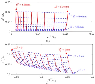
𝛽𝑉, 𝛽𝐻, 𝛼𝑉, and 𝛼𝐻, as it is illustrated in Fig. 2. As shown in Fig. 2 (a), the variation of Ls
Vand Ls
H (the lengths of the slot arms) enables to control 𝛼𝑉and 𝛼𝐻 (i.e. the amount of energy leaked out by each LW). Analogously, the variation of LrVand LrH (the heights of the ridges) allows to control 𝛽𝑉 and 𝛽𝐻 (i.e.
the phase velocity of each LW), as evidenced in Fig. 2 (b). Therefore, a desired combination of [𝛽𝑉,𝛽𝐻, 𝛼𝑉,𝛼𝐻] can be realized by properly choosing the quadruplet[LrV, LrH, LsV, LsH]. For this reason, the horizontal ridges can be different from the vertical one, and the two slot arms are not necessarily equal.
(a)
(b)
Fig. 2. Normalized (a) leakage rates varying LsVand LsHwith steps of 0.12 mm
(LrH = LrV = 0), (b) phase constants varying LrVand LrH, with steps of 0.1 mm
(LsV= 4.2 mm and LsH = 3.5 mm). Results are obtained using HFSS full-wave
solver at 23.28 GHz. y x z 𝐿𝐴 OMT z x y Modulated ridges a 𝐿𝐴 a t a P x y 𝐿𝑠𝐻 𝐿𝑉𝑠 𝐿𝑟𝐻 𝐿𝑟𝑉 𝑃 𝐿𝑠𝑉 = 4.86mm 𝐿𝑠𝑉 = 6.06mm 𝐿𝐻𝑠 = 4.16mm 𝐿𝐻𝑠 = 5.36mm 𝐿𝑟𝐻 = 0 𝐿𝐻𝑟 = 1mm 𝐿𝑉𝑟 = 1mm 𝐿𝑉𝑟 = 0
Accepted
manuscritpt
It is well-known that, by achieving an illumination with cosine or Taylor magnitude while keeping a constant phase distribution, it is possible to reduce the SLL of an antenna without suffering from phase aberration [13]. To this aim, and following (2), it is necessary to tune 𝛼𝑉 𝐻⁄ (𝑦) along the LWA length without modifying 𝛽𝑉 𝐻⁄ (𝑦) [10]-[12].This performance enhancement is here pursued for both polarizations at the same time. Additionally, equal pointing angles are targeted for both beams, thus implying 𝛽𝑉(𝑦) = 𝛽𝐻(𝑦). This objective is reached in the following section by modulating appropriately the geometry of the antenna along the y-axis.
III. ANTENNA DESIGN
In this section the process followed to reduce the LWA SLL is illustrated progressively by means of three examples. In the first case, a simple non-modulated antenna without ridges is considered. The second design grants the control over 𝛽𝑉 and
𝛽𝐻 thanks to the insertion of the three ridges. Their heights are constants along the antenna length. Finally, a LWA is designed including ridges with modulated heights and crossed-slots with different dimensions, thus providing low SLL for V and H polarizations. The design process is carried out through full-wave HFSS simulations. The considered specifications are inspired from Iridium, a typical in-orbit constellation using ISLs at 23.28GHz [14], pursuing theoretical radiation efficiencies of 90% for both polarizations. The periodicity P is chosen to be smaller than half a wavelength at the operation frequency in order to remain below the grating-lobe regime [12]. Main dimensions are detailed in the caption of Fig. 1.
(a) (b)
Fig. 3. Simulated radiation pattern (dB) (a) LWA without ridges (LsV = 5.88
mm and LsH = 5.08 mm), (b) triple-ridge LWA (LrH = 0.2 mm, LrV = 0.75 mm,
LsV = 5.92 mm and LsH = 5.1 mm).
A. Design 1: Uniform LWA without Ridges
This first design follows directly from [4], where a leaky waveguide perforated with crossed slots is considered. Since the structure is uniform, all slots are equal, and the LWs wavenumbers are also constant along the antenna length (i.e. 𝛼𝑉 𝐻⁄ (𝑦)= 𝛼𝑉 𝐻⁄ 𝑎𝑛𝑑 𝛽𝑉 𝐻⁄ (𝑦)= 𝛽𝑉 𝐻⁄
). The values of
L
s V/Hare given in the caption of Fig. 3; they are adjusted to achieve the desired radiation efficiencies following:
𝜂𝑅𝐴𝐷𝑉/𝐻 = 1 − exp (−2𝛼𝑉 𝐻⁄ 𝐿
𝐴) [12]. The resulting design is simulated, obtaining 𝜂𝑅𝐴𝐷𝑉 = 87%, 𝜂𝑅𝐴𝐷𝐻 = 91%, and the dual-polarized radiation pattern of Fig. 3 (a). The first remarkable feature in this figure is the fact that both beams do not point at the same direction (there is a 3° difference between them).
Though the section of the LWA is squared, 𝛽𝑉and 𝛽𝐻 are not equal, and thus, neither are 𝜃𝑅𝐴𝐷𝑉 and 𝜃𝑅𝐴𝐷𝐻 . The slots are responsible for this difference, they affect the dispersion of each mode differently. As Fig. 3 (a) also shows, SLLV/H are around -12 dB. This value is expected from this uniform LWA, since |𝑀𝑉 𝐻⁄ (𝑦)| is exponential [12].
B. Design 2: Uniform Triple-Ridge LWA
In order to illustrate the possibility to correct the pointing angle deviation, the previous LWA is here loaded with three ridges whose heights are constant along the antenna length. The slots dimensions and the heights of these ridges are now chosen in order to achieve, at the same time, high radiation efficiencies and equal pointing angles 𝛽𝑉(𝑦) = 𝛽𝐻(𝑦) (dimensions are given in the caption of Fig. 3). The resulting radiation patterns are shown in Fig. 3 (b), with 𝜂𝑅𝐴𝐷𝑉 = 88% and 𝜂𝑅𝐴𝐷𝐻 = 92%. Both beams point now at the same direction 𝜃𝑅𝐴𝐷𝑉/𝐻= 37°. The values of SLLV/H are unchanged with respect to the previous design, since the antenna illumination is again exponential.
C. Design 3: Modulated triple-ridge LWA
By modulating the heights of the ridges and the crossed-slots dimensions along the y-axis (as illustrated in Fig. 1) the SLLV/H are here reduced while maintaining high 𝜂𝑅𝐴𝐷𝑉/𝐻 and equal 𝜃𝑅𝐴𝐷𝑉/𝐻. Fig. 4 (a) shows the cosine distribution aimed for both |𝑀𝑉 𝐻⁄ (𝑦)|
, together with the corresponding needed values of 𝛼𝑉 𝐻⁄ (𝑦) (they are obtained applying (2)). It also includes the desired constant phase distribution 𝛽𝑉 𝐻⁄ (𝑦), thus providing all the useful information for our synthesis approach. As explained in Section II, the antenna structure allows to adjust properly the geometry of each unit cell (the quadruplet [Lr
V , Lr H , Ls V , Ls
H]) in order to provide desired LWs wavenumbers ([𝛽𝑉, 𝛽𝐻, 𝛼𝑉, 𝛼𝐻]). The resulting geometrical parameters are shown in Fig. 4 (b). Ideal smooth values are discretized at each crossed-slot position (with period P), consequently conducing to stepped ridges where one step corresponds to one unit-cell.
(a)
(b)
Fig. 4. (a) Normalized illumination, required phase constants and leakages, (b) slots and ridges dimensions (mm).
|𝑀𝑉 𝐻⁄ (𝑦)| 𝛼𝑉 𝐻⁄ (𝑦)/𝑘0
Accepted
manuscritpt
By inspecting Fig. 4 it can be understood that the modulation of the crossed-slots arms (LsV, LsH) allows achieving the required 𝛼𝑉 𝐻⁄ (𝑦) and thus the desired cosine amplitude for SLLV/H reduction. However, as demonstrated in the case of Section III.A, the crossed-slots perforations alter
𝛽𝑉and 𝛽𝐻. Hence, due to the modulation of the slots, 𝛽𝑉 𝐻⁄ (𝑦) could also differ for each unit-cell, which means that each crossed-slot would radiate in a different direction. In order to obtain the same pointing angle for both polarizations and avoid phase aberration, modulated ridges are used to guarantee that 𝛽𝑉(𝑦) = 𝛽𝐻(𝑦) = 𝛽𝑉 𝐻⁄ .
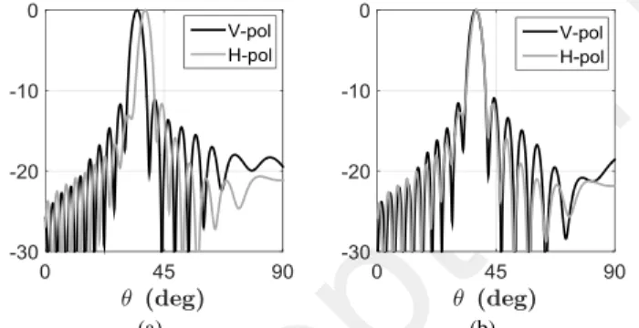
The simulated radiation patterns are shown in Fig. 5 (a), obtaining 𝜂𝑅𝐴𝐷𝑉 = 87% and 𝜂
𝑅𝐴𝐷𝐻 = 92%. As expected from the cosine illumination, the SLLV/H have decreased and they are around -19dB. Pointing angles are only 0.7° far one from another, proving the success in the control of 𝛽𝑉 𝐻⁄ (𝑦). Poynting vectors, inspected in the near field region, are shown in Fig. 5 (b), evidencing its cosine magnitude for the two polarizations and constant orientation.
(a) (b)
Fig. 5. (a) Simulated radiation pattern (dB) of the modulated antenna, (b) Poynting vectors of the modulated antenna in the near field region.
IV. MONOLITHIC SLAMANUFACTURING &MEASUREMENTS
The triple-ridge modulated antenna designed in Section III.C is manufactured using SWISSto12’s SLA technique [1]-[4], [6]. The resulting prototype is shown in Fig. 6. The antenna is firstly 3D-printed using a non-conductive UV-photosensitive polymer, which is layer-by-layer solidified by a laser. Secondly, the resulting piece is treated to ensure high quality of the subsequent plating phase. Finally, chemical plating with copper is applied to make all surfaces RF-conductive. Thanks to the use of a proprietary electroless process, monolithic manufacturing is possible profiting also from both low cost and weight. The tolerance of the manufacturing process is on the order of 40 um, whereas the surface roughness is around 250 nm. The thickness of the metal layer is controllable, and components at 20 GHz are generally plated with 6 um of Copper (approximately ten times the skin depth). The antenna has been printed along the
y-axis (each layer of polymer belongs to the ZX-plane), to
favor good symmetry (both for ridges and slots) with respect to the ZY-plane regardless of SLA tolerances. Consequently, the OMT V-port is tilted of 30° to 3D-print a self-supported piece, as it was also done in [15]. Such an action improves drastically the accuracy of the prototype without affecting the OMT performance. It is also worth mentioning that the production of this antenna using other manufacturing techniques would involve different blocks and the
combination of several fabrication processes, thus resulting in a very bulky and complicated piece [3].
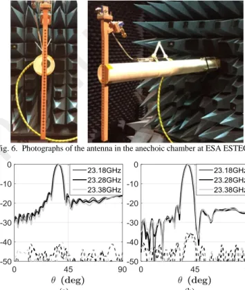
Measured radiation patterns exciting either the V or H-port are respectively shown in Fig. 7 (a) and (b) within the Iridium ISL band. Maximum directivities at 23.28 GHz are
𝐷𝑚𝑎𝑥𝑉 =17.84 dB and 𝐷𝑚𝑎𝑥𝐻 = 18.22 dB, which are only - 0.31 dB and - 0.17 dB below simulations. The values for 𝜃𝑅𝐴𝐷𝑉/𝐻in the whole band differ maximum 1° from full wave results, and the deviation in measured SLLV/H is maximum + 2.35 dB and + 0.21 dB from simulations. These differences can be due to the alignment in the measurement setup and SLA precision [4]. Additionally, very low cross-polarization levels (< - 35 dB) are measured for both polarizations, thus proving the high precision in the SLA process regarding the symmetry of the structure in the ZY-plane. In the operation band, measured return losses and ports isolation remain below – 16 dB and - 40 dB, respectively.
Fig. 6. Photographs of the antenna in the anechoic chamber at ESA ESTEC.
(a) (b)
Fig. 7. Normalized directivity patterns in dB exciting: (a) V-port, (b) H-port. Solid/dashed lines represent respectively Co/Cross-polarization.
V. CONCLUSIONS
In this letter the strength of SLA additive manufacturing technique to enhance the performance of K-band antennas has been demonstrated. A new type of modulated triple-ridge LWA has been proposed, allowing for dual-polarization with low SLL. This approach is successfully validated through the SLA manufacturing and measurement of a prototype.
ACKNOWLEDGMENTS
The authors would like to thank both Mr. E. Van Der Houwen and Mr. L. Rolo from ESA ESTEC for their valuable help during the measurements campaign, Prof. J. R. Mosig from EPFL for his generous support to this activity, and L. Simon from Swissto12 for his inputs on SLA.
y z
y
z H-pol
Accepted
manuscritpt
REFERENCES
[1] M. van der Vorst and J. Gumpinger, "Applicability of 3D Printing Techniques for Compact Ku-band Medium/High-Gain Antennas," in
10th European Conference on Antennas and Propagation, Davos, 2016.
[2] A. I. Dimitriadis et al., "Polymer-Based Additive Manufacturing of High-Performance Waveguide and Antenna Components," Proceedings
of the IEEE, vol. 105, no. 4, pp. 668-676, April 2017.
[3] J. S. Silva, M. García-Vigueras, T. Debogović, J. R. Costa, C. A. Fernandes and J. R. Mosig, "Stereolithography-Based Antennas for Satellite Communications in Ka-Band," Proceedings of the IEEE, vol. 105, no. 4, pp. 655-667, April 2017.
[4] M. García-Vigueras, E. Menargues, T. Debogovic, E. de Rijk and J. R. Mosig, "Cost-effective dual-polarized leaky-wave antennas enabled by three-dimensional printing," IET Microwaves, Antennas & Propagation, vol. 11, no. 14, pp. 1985-1991, November 2017.
[5] P. Booth and E. V. Lluch, "Enhancing the Performance of Waveguide Filters Using Additive Manufacturing," Proceedings of the IEEE, vol. 105, no. 4, pp. 613-619, April 2017.
[6] E. Menargues et al., "Compact Orthomode Transducer with Broadband Beamforming Capability," in IEEE MTT-S International Microwave
Symposium (IMS), Philadelphia, 2018.
[7] R. Radhakrishnan, W. W. Edmonson, F. Afghah, R. M. Rodriguez-Osorio, F. Pinto and S. C. Burleigh, "Survey of Inter-Satellite Communication for Small Satellite Systems: Physical Layer to Network Layer View," IEEE Communications Surveys & Tutorials, vol. 18, no. 4, pp. 2442-2473, May 2016.
[8] C. J. Vourch and T. D. Drysdale, "V-Band “Bull's Eye” Antenna for CubeSat Applications," IEEE Antennas and Wireless Propagation
Letters, vol. 13, pp. 1092-1095, 2014.
[9] U. Beaskoetxea, S. Maci, M. Navarro-Cía and M. Beruete, "3-D-Printed 96 GHz Bull's-Eye Antenna With Off-Axis Beaming," IEEE
Transactions on Antennas and Propagation, vol. 65, no. 1, pp. 17-25,
January 2017.
[10] P. Lampariello, F. Frezza, H. Shigesawa, M. Tsuji and A. A. Oliner, "A Versatile Leaky-Wave Antenna Based on Stub-Loaded Rectangular Waveguide: Part .I - Theory," IEEE Transactions on Antennas and
Propagation, vol. 46, no. 7, pp. 1032-1041, July 1998.
[11] A. R. Mallahzadeh and M. H. Amini, "Design of a Leaky-Wave Long Slot Antenna Using Ridge Waveguide," IET Microwaves, Antennas &
Propagation, vol. 8, no. 10, pp. 714-718, July 2014.
[12] A. A. Oliner and D. R. Jackson, "Leaky-wave antennas," in Antenna
Engineering Handbook, Fourth Edition, McGraw-Hill, 2007.
[13] C. A. Balanis, Antenna Theory: Analysis and Design, Second ed., John Wiley & Sons, Inc, 1997.
[14] K. Maine, C. Devieux and P. Swan, "Overview of IRIDIUM satellite network," in WESCON, San Francisco, CA, USA, 1995.
[15] O. A. Peverini et al., "Selective Laser Melting Manufacturing of Microwave Waveguide Devices," Proceedings of the IEEE, vol. 105, no. 4, pp. 620-631, April 2017.