Behaviour of alumina powder
fed into molten electrolytic bath
by
Csilla Kaszas
Under the supervision of Laszlo Kiss and Sandor Poncsak
Dissertation submitted at the University of Québec at Chicoutimi, Département des
Sciences Appliquées, in fulfillment of the requirements for PhD in Engineering
Defended on 25
thNovember 2020
Jury:
Dilip Sarkar, professor, UQAC, chairman
Robert Chahine, project manager, Rio Tinto, France, external member Gervais Soucy, professor, Sherbrook University, external member
Québec, Canada ©Csilla Kaszas, 2020
ii
Acknowledgements
First and foremost, I would like to express my gratitude to Laszlo Kiss, my supervisor, for his support, patience and guidance that ensured the completion of my thesis. I would also like to extend my thanks to every present and former member of GRIPS who contributed to my work in any way: Patrice Paquette, for his technical support that ensured the realisation of the envisioned experiments, Anthony le Noc, who conducted a large number of experiments in the analog setup on my behalf, Thomas Roger, who prepared and analysed dozens of compressed alumina discs and continued to assist me in various experiments as a fellow student, Sandor Poncsak for accepting the responsibility of becoming my co-supervisor, and many others.
For the execution of the porosity analysis, I owe thanks to Houshang Alamdari and Francois Chevarin from University Laval.
I would like to thank the Natural Sciences Engineering Research Council of Canada and Rio Tinto Aluminium for their financial support. A part of the research presented was financed by the Fonds de recherche du Québec -Nature et technologies by the intermediary of the Aluminium Research Centre – REGAL.
iii
Résumé
La dissolution de l'alumine (oxyde d'aluminium) dans l’électrolyte est un procédé essentiel dans la production d'aluminium, le deuxième métal le plus utilisé sur Terre. Dans les cellules actuelles de réduction d'aluminium, la poudre d'alumine de fonderie est ajoutée à la surface du bain cryolitique fondu à des doses variant entre 0,5 et 2 kg. Bien que la dissolution d'une poudre dans son solvant puisse sembler anodine, ce processus présente plusieurs particularités qui entravent la dispersion rapide de l'alumine. La dissolution douteuse peut saper le contrôle cellulaire, et l'alumine non dissoute peut former des agglomérats qui peuvent diminuer l'efficacité et la durée de vie de la cellule.
L'objectif de cette thèse était d'analyser les mécanismes qui favorisent la formation d'agglomérats, et d'entraver ainsi la dispersion rapide de l'alumine ajoutée dans le bain cryolitique, en se concentrant principalement sur:
• la formation du radeau: l'étalement de la poudre, injectée sur la surface du bain;
• l'évolution des radeaux d'alumine, en ce qui concerne la flottation du radeau à la surface du bain;
• le comportement à la flottation des agglomérats à l'interface bain-métal.
Les méthodes utilisées dans ce travail comprennent la modélisation mathématique, des expériences en bain cryolitique, l'analyse de radeaux d'alumine et des expériences dans des systèmes analogiques poudre-liquide.
Un modèle mathématique a été développé pour analyser les conditions de flottation en régime permanent d'objets axisymétriques sur une surface liquide. Le modèle a été appliqué à la surface du bain électrolytique. Pour l'interface bain-métal, le modèle statique a été étendu pour prendre en compte la vitesse initiale de l'agglomérat et la dynamique de la pénétration de l'interface.
L'angle de contact entre l'alumine et le bain cryolitique (un paramètre d'entrée important pour le modèle de flottation) a été mesuré par la méthode Wilhelmy.
Des expériences ont été menées dans le bain cryolitique pour étudier et analyser la formation de radeaux. La teneur en humidité a été identifiée comme une propriété importante de l'alumine qui influence la forme, la structure et la microstructure du radeau d'alumine, se formant lors de l'injection. Des échantillons de radeau ont été préparés par lixiviation pour éliminer la cryolite, révélant la structure d'alumine sous-jacente, puis la porosité était analysée. Des disques d'alumine compressés en tant que radeaux d'alumine artificiels ont été préparés pour obtenir des radeaux de forme et de taille contrôlée, tout en laissant les principaux processus inchangés. L'uniformité des radeaux artificiels a permis de comparer facilement les échantillons prélevés après différentes étapes et de suivre l'évolution de la ligne d'infiltration
iv
dans le temps. La densité des radeaux, ainsi que les séquences vidéo des expériences ont prouvé que la tension superficielle peut contribuer à la flottation des radeaux d'alumine.
Un modèle bidimensionnel de radeaux d'alumine a été créé pour prédire la solidification du bain, l'infiltration et la densité apparente, donc la possibilité de flottation pour le radeau. Les propriétés thermiques de l'alumine primaire de fonderie ont été mesurées par un dispositif de chauffage à rampe monotone, et en raison de la structure complexe de la porosité de l'alumine, un modèle à deux niveaux a été appliqué pour pouvoir estimer sa conductivité thermique avec différentes densités.
Le détachement des grains saturés ou des amas du radeau principal diminuerait sa taille ainsi que sa densité apparente. La désintégration d'un radeau est dictée par les effets concurrents et la dynamique du frittage et de la dissolution. Bien que la dissolution soit souvent considérée comme le but ultime de la recherche concernant le comportement de l'alumine dans l'électrolyte, elle devrait plutôt être considérée comme un processus parallèle mais opposé au frittage, et enquêter simultanément sur les deux. Dans le cadre de ce travail, la teneur en carbone a été identifiée comme un facteur favorisant la désintégration en affaiblissant le frittage.
Des injections de poudre dans des systèmes liquide-liquide analogiques à basse température ont été effectuées pour mieux comprendre leurs interactions. Alors que dans de nombreux aspects, les systèmes analogiques ne représentent pas fidèlement le système alumine-bain-aluminium, certains phénomènes peuvent s'appliquer à la cellule d'électrolyse. Ces observations sont d'une importance particulière pour l'interface bain-métal.
Abstract
The dissolution of alumina (aluminium-oxide) in an electrolyte is an essential process in the production of aluminium, the second most commonly used metal on Earth. In the state-of-the-art aluminium reduction cells, smelter grade alumina powder is added on the surface of the molten cryolitic bath in doses varying between 0.5-2 kg. While dissolving a powder in its solvent might seem trivial, there are several particularities to this process that hinder the rapid dispersion of alumina. The dubious dissolution may undermine the cell control, and the undissolved alumina could form agglomerates that can decrease the efficiency and lifetime of the cell.
The objective of this PhD was to analyse the mechanisms that promote the formation of agglomerates, and hinder the fast dispersion of alumina added into cryolitic bath, mostly focusing on:
the raft formation: the spreading of the powder, injected onto the bath surface; the evolution of alumina rafts, with regard to the flotation of the raft on the bath
v
the flotation behaviour of agglomerates on the bath-metal interface.
The methods used in this work include mathematical modelling, experiments in cryolitic bath, analysis of alumina rafts, and experiments in analog powder-liquid systems.
A mathematical model was developed to analyse the conditions of steady-state flotation of axisymmetric objects on a liquid surface. The model was applied to the surface of the electrolytic bath. For the bath-metal interface, the static model was extended, to consider the initial velocity of the agglomerate and dynamics of the interface penetration.
The contact angle between alumina and cryolitic bath (an important input parameter for the flotation model) was measured by Wilhelmy method.
Experiments were conducted in the cryolitic bath to study and analyse raft formation. Moisture content was identified as an important property of alumina that influences the shape, structure, and microstructure of the alumina raft, forming upon injection. Raft samples were prepared by leaching to remove cryolite, revealing the underlying alumina structure, then the pore structure analysed.
Compressed alumina discs as artificial alumina rafts were prepared to obtain rafts with controlled shape and size, while leaving the main processes (bath solidification, infiltration, sintering and dissolution) unchanged. The uniformity of the artificial rafts permitted the easy comparison between samples removed after different stages, and to follow the advancement of the line of infiltration in time. The density of the rafts, along with the video footage of the experiments proved that the surface tension can contribute to the flotation of alumina rafts. Two-dimensional thermal model of alumina rafts was created to predict bath solidification, infiltration and apparent density – therefore possibility of flotation for the raft. Thermal properties of primary smelter grade alumina were measured by monotonic ramp heating device, and due to the complex pore structure of the alumina, a two-level model was applied to be able to estimate its thermal conductivity with different packing densities.
The detachment of infiltrated grains or clumps from the main body of the raft decreases its size and also its apparent density. The disintegration of a raft is controlled by the opposing effects and the dynamics of sintering and dissolution. While dissolution is often considered as the main goal of research concerning the behaviour of alumina in the electrolyte, it should rather be considered as an opposing but parallel process to sintering, and should be investigated simultaneously. In the frame of this work, carbon content was identified as a factor that aids disintegration via weakened sintering.
Powder injections in low-temperature analog liquid-liquid systems were conducted to gain insight on their interactions. While in many aspects, the analog systems fail to represent faithfully the alumina-bath-aluminium system, certain phenomena may apply for the electrolysis cell. These observations are of special importance for the liquid-liquid interface.
vi
Table of contents
Acknowledgements ... ii Résumé ... iii Abstract ... iv Table of contents ... vi List of tables... ix List of figures ... ixList of equations ... xiii
Notation ... xiv
Introduction ... 1
1 Context of research problem ... 7
1.1 Smelter grade alumina ... 7
1.1.1 Production of SGA ... 7
1.1.2 Structure ... 8
1.1.3 Density ... 8
1.1.4 Moisture content ... 8
1.1.5 Thermal properties of alumina powder ... 9
1.1.6 Other properties; interconnectedness ... 10
1.2 Properties of electrolytic bath ... 10
1.2.1 Composition ... 10
1.2.2 Temperature ... 11
1.2.3 Density ... 11
1.2.4 Surface tension ... 11
1.3 Behavior of alumina in the bath ... 12
1.3.1 Dissolution ... 12
1.3.2 Crusting, agglomeration and sintering ... 13
1.3.3 Flotation on the bath surface ... 15
1.3.4 Flotation on BMI ... 16
1.3.5 Sludge ... 17
1.3.6 Alumina phases ... 17
1.3.7 Secondary alumina ... 17
vii
2 Conditions of steady-state flotation on bath surface ... 19
2.1 Mathematical model ... 19
2.1.1 Force balance of a floating axisymmetric object in equilibrium ... 19
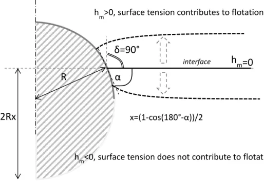
2.1.2 Meniscus height... 20
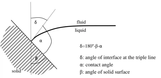
2.1.3 Angle of interface at the triple line ... 24
2.1.4 Shape of the floating object ... 26
2.1.5 Dimensionless equations ... 30
2.2 Results ... 31
2.2.1 General (dimensionless, contact angle dependent) ... 31
2.2.2 Flotation limit on cryolitic bath surface ... 33
2.3 Comparison of model with experiments on bath surface ... 35
2.3.1 Compressed alumina discs ... 35
2.3.2 Alumina spheres ... 36
2.3.3 Gravimetric tests ... 37
3 Alumina raft formation– shape and role of surface tension ... 38
3.1 Description of the experimental setup... 38
3.1.1 Smelter grade alumina ... 39
3.1.2 Alumina injections with video recording ... 40
3.1.3 Compressed alumina discs as artificial rafts ... 41
3.1.4 Gravimetric system ... 42
3.2 Injection of SGA – Raft formation and shape ... 43
3.2.1 Injection of alpha alumina – effect of bulk density ... 45
3.2.2 Particle size/fines ... 47
3.2.3 Effect of moisture content on the shape of alumina rafts ... 47
3.2.4 Bath solidification ... 51
3.3 Surface tension ... 53
3.3.1 Contact angle ... 54
3.3.2 Roughness of smelter grade alumina ... 59
3.3.3 Influence of foreign particles on the bath surface ... 60
3.3.4 Raft contacting carbon wall/anode during formation ... 63
3.3.5 Agitation of bath surface ... 65
viii
4.1 Thermal behaviour of alumina rafts ... 68
4.1.1 Compressed discs as artificial rafts... 68
4.1.2 Measurement of thermal properties of alumina ... 78
4.1.3 Two-dimensional thermal model of raft ... 88
4.2 Influence of moisture content on the structure of alumina rafts ... 93
4.2.1 Experimental... 93
4.2.2 Composition of rafts ... 96
4.2.3 Porosity analysis ... 98
4.2.4 Other possible effects for larger quantities of powder ... 103
4.3 Infiltration experiments in steel tubes ... 104
4.3.1 Experimental... 104
4.3.2 Results ... 105
4.3.3 Secondary alumina ... 109
4.4 Disintegration: sintering vs dissolution ... 112
4.4.1 Carbon content ... 114
5 Phenomena at the bath-metal interface ... 118
5.1 Steady-state flotation ... 118
5.1.1 Equivalent system for liquid-liquid interface ... 118
5.1.2 Model results ... 118
5.2 Dynamic model of flotation and piercing of the interface ... 122
5.2.1 Additional parameters and assumptions in the dynamic model ... 122
5.2.2 Results ... 127
5.2.3 Comparison of model with experiments ... 136
5.3 Experiments with analog systems ... 139
5.3.1 Similarity conditions ... 140
5.3.2 Small model with monosodium-glutamate, water and ethyl trichloroacetate... 143
5.3.3 Larger quantities of MSG injections ... 145
5.3.4 Various phenomena observed in analog experiments in relevance to the electrolysis cell ... 146
5.3.5 Limitations of analog models ... 149
Conclusions ... 151
ix
List of tables
Table 1 : Literature on the thermal properties of SGA ... 10
Table 2: Impurities of SGA ... 39
Table 3: Capillary rise in alumina/sapphire tubes; calculated contact angle ... 56
Table 4: Bath properties used for the calculation at 960 °C ... 56
Table 5: Sensitivity analysis for contact angle measurement with capillary rise method ... 57
Table 6: Compressed disc removals ... 68
Table 7: Equations for monotonic (ramp) heating measurements ... 80
Table 8: Series of measurements for thermal properties of SGA ... 81
Table 9: Equivalent thermal conductivity of SGA [W/mK] ... 81
Table 10: Connection between the different levels of SGA porosity, and estimated values ... 84
Table 11: BET surface area of samples ... 99
Table 12: Carbon content of injected alumina ... 114
Table 13: Behaviour of alumina on the bath surface with or without added carbon ... 115
Table 14: Penetration of water surface by micro-beads, test results ... 137
Table 15: Dimensionless numbers in the electrolysis cell and the analog model ... 142
List of figures
Figure 1: Schematic drawing of an aluminium electrolysis cell... 2Figure 2: Different phases in the life of alumina raft/agglomerate ... 3
Figure 3 Structure of the document ... 6
Figure 4: Main processes and material flow of aluminium production ... 7
Figure 5: Forces acting on a floating axisymmetric object ... 19
Figure 6: Meniscus profile, illustration of variables ... 21
Figure 7: Numerical solutions for meniscus profile at the surface of cryolitic bath ... 22
Figure 8: Dimensionless meniscus height as a function of triple line radius and angle of the interface ... 23
Figure 9: Maximum meniscus height, minimum angle of interface, as a function of radius, on the bath surface ... 24
Figure 10: Determination of the angle of interface at the triple line, on smooth solid surface ... 25
Figure 11: Illustration for Gibbs extension to the Young-Dupré law ... 26
Figure 12: Geometries and corresponding force terms used in the present flotation model ... 27
Figure 13: Contact angle limiting the position of a floating disc ... 27
Figure 14: Surface tension stabilizing tilted disc with δ>0, opposite effect on disc with δ<0 ... 28
Figure 15: Dependence of the angle of interface, meniscus height and triple line length on the relative immersion of a floating sphere ... 29
x
Figure 17: Dimensionless flotation limit of spheres ... 31
Figure 18: Dimensionless flotation limit of discs, h/d=2/3; dashed line: the angle delta limited at 0 ... 32
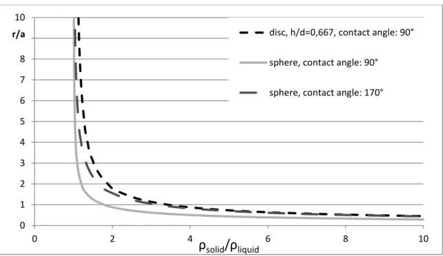
Figure 19: Dimensionless flotation limit, as maximal radius, with different contact angles and geometries ... 32
Figure 20: Flotation limit on bath surface, contact angle: 30° ... 33
Figure 21: Density limit of a fixed volume of alumina raft, assuming spreading to disc-shape .... 34
Figure 22: Density of samples, results from repeated experiments B and C ... 36
Figure 23: Placement and flotation of porous alumina sphere (desiccant) on cryolitic bath surface ... 36
Figure 24: Liquidus temperature in the experimental setup (FactSage) ... 39
Figure 25: Particle size distribution of smelter grade alumina ... 40
Figure 26: Sketch of experimental setup for alumina powder injections ... 40
Figure 27: Insertion of alumina disc onto the bath surface ... 41
Figure 28: Schema of gravimetric system ... 43
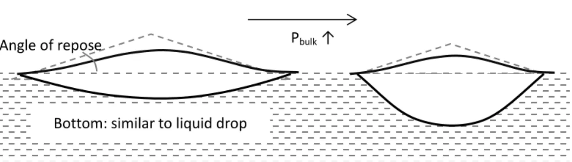
Figure 29: Schematic description of flotation behaviour of powders on the surface of liquids ... 44
Figure 30: Powder injection, effect of density ... 45
Figure 31: Alpha alumina raft on cryolitic bath surface (2.5g) ... 46
Figure 32: Shape of powder on liquid surface, effect of bulk density... 46
Figure 33: Alumina rafts on bath surface, influence of moisture content ... 48
Figure 34: Alumina rafts removed from bath after 45 seconds retention time, (Loose alumina powder from dried alumina rafts was removed) ... 49
Figure 35: Effect of moisture content of alumina upon injection into cryolitic bath ... 49
Figure 36: Geysers around a plugged feeder hole, image from a video taken at RTA plant, 201150 Figure 37: Compressed alumina disc on bath surface ... 51
Figure 38: Sinking of artificial raft left: view right after sinking - right: removal of disc, top detached ... 51
Figure 39: Frozen bath around compressed alumina disc (low superheat) ... 52
Figure 40 Gravimetric test on alumina rod in cryolitic bath, result vs expected behaviour without solidification ... 53
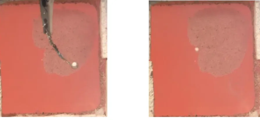
Figure 41: Surface tension of bath can contribute to the flotation of artificial raft ... 54
Figure 42: Schema of capillary rising measurement and results of successful experiments ... 56
Figure 43: Buoyant and surface tension forces acting on an alumina rod, immersed into cryolitic bath ... 58
Figure 44.: SEM Images of primary smelter grade alumina ... 59
Figure 45.: Scanning electron microscope image of recrystallized alumina at the front of infiltration of a compressed alumina disc ... 60
Figure 46: Approximate shape of meniscus around a single floating object (solid line), and around two identical floating objects (dashed line) ... 61
Figure 47: Different foreign particles on bath surface ... 62
Figure 48: Particle raft on bath surface without overhead light, the lighter patches seemingly swirling under the surface ... 62
xi
Figure 49: Contaminated surface around compressed alumina disc, process of sinking ... 63
Figure 50: Suspended alumina raft, top view 2.5 g (10.13, 3rd) ... 64
Figure 51: Suspended alumina raft, angled view 5g (10.22, 3rd) ... 64
Figure 52: Sketch of suspended alumina raft ... 65
Figure 53: Disturbances of the bath surface in the experimental setup (16.07.11) ... 65
Figure 54: Structure of chapter ... 68
Figure 55:SEM image of alumina disc infiltrated by bath (sample upside-down; 30 s retention time). ... 69
Figure 56: Saturation of alumina by bath in compressed disc, flotation time: 90 sec ... 70
Figure 57: Infiltration front in artificial alumina rafts, series B and C ... 72
Figure 58: Characteristics of infiltrated artificial raft, series B ... 73
Figure 59: Evolution of the mass of artificial rafts ... 74
Figure 60: Correlation between mass growth of discs and infiltration ... 75
Figure 61: Density of samples, series A, B and C ... 76
Figure 62: Artificial raft on bath surface via FLIR infrared camera... 77
Figure 63: Temperature of the top of alumina disc on bath surface with FLIR camera ... 78
Figure 64: Adjusted results for series C and D ... 82
Figure 65: Thermal conductivity (three-point measurements) ... 83
Figure 66: Alumina powder (SEM image) and model geometry ... 84
Figure 67: Effective thermal conductivity of alumina, model results ... 85
Figure 68: Approximate emissivity of alumina (25% porosity) ... 86
Figure 69: Effective thermal conductivity for radiation in function of temperature ... 87
Figure 70.: Shape of frozen bath around an alumina disc, different zones of mathematical model ... 88
Figure 71: Thermal conductivity of alumina disc in thermal model ... 89
Figure 72: 700°C isotherms in discs, for 35°C superheat and 500 °C temperature above disc .... 90
Figure 73: Temperature distribution in disc after 120 and 240 seconds ... 91
Figure 74 Evolution of temperature and density of compressed disc, result of model, superheat: 35 °C ... 92
Figure 75: Evolution of the thickness of frozen layer and density of compressed disc, result of model, air temperature: 500 °C ... 92
Figure 76: SEM imaging of untreated (left) and leached (right) primary alumina (x1000) ... 95
Figure 77: Front of infiltration for compressed alumina disc, ’A’ photo with digital microscope, ’B’ SEM imaging ... 96
Figure 78: Composition of raft samples, assuming no dispersion occurred upon injection ... 97
Figure 79: Alumina content of infiltrated powder ... 98
Figure 80: Porosity analysis of SGA ... 100
Figure 81: Pore size distribution of alumina rafts (BJH) ... 101
Figure 82: Pore size distribution of leached raft samples and alumina (DFT) ... 102
Figure 83: Structure of alumina raft with or without moisture ... 103
Figure 84: Proposed mechanism for local behaviour of thick alumina raft ... 104
xii
Figure 86: Infiltration height in alumina powder ... 106
Figure 87: Capillary rising in vertical tube, contact angle 30° ... 107
Figure 88: Apparent density of infiltrated alumina ... 108
Figure 89: Density of infiltrated alumina, series B ... 108
Figure 90: Photo of cross-cut samples from series A, infiltrated alumina in tubes ... 110
Figure 91: Temperature difference between side and center of tube filled with alumina... 111
Figure 92: Disintegration of a raft ... 112
Figure 93: Effect of surface movement on raft disintegration or sinking ... 113
Figure 94: Microscopic image of secondary alumina ... 114
Figure 95: Alumina rafts 10 s after injection (camera was out of focus on the 1st day) ... 115
Figure 96: Treatment of images of alumina rafts with Matlab ... 116
Figure 97.: Result of image processing, disintegration of alumina rafts, 1st injection ... 116
Figure 98: Modification of flotation model to account for the upper fluid ... 118
Figure 99: Flotation limit on bath-metal interface ... 119
Figure 100: Dependence of flotation limit of discs on height-diameter ratio, on BMI ... 120
Figure 101: Maximal thickness of disc shape agglomerate on the BMI ... 121
Figure 102:Mass limit of disc-shaped agglomerates on the BMI ... 121
Figure 103: Flat disc arriving at the interface with an angle ... 123
Figure 104: Different stages of interface penetration ... 124
Figure 105: Displaced volume at different stages of sinking... 126
Figure 106: Approximation of meniscus height and angle of interface for dynamic interface penetration model ... 127
Figure 107: Agglomerate impact on bath-metal interface (sinking) ... 128
Figure 108: Agglomerate impact on bath-metal interface (floating) ... 128
Figure 109: Critical density for agglomerate penetration on BMI, H/d=2/3 ... 129
Figure 110: Critical velocity for agglomerate penetration on BMI, H/d=2/3 ... 130
Figure 111: velocity of agglomerate descending from bath surface onto bath-metal interface 131 Figure 112: Critical density of interface penetration, fixed bath height ... 131
Figure 113: Critical density of interface penetration, influence of relative thickness ... 132
Figure 114: Critical thickness for interface penetration ... 132
Figure 115: Mass limit of interface penetration... 133
Figure 116: Effect of contact angle on the critical density for interface penetration ... 134
Figure 117 : Influence of contact angle on critical velocity of interface penetration (wetting-non-wetting) ... 134
Figure 118: Limits for the interface at the triple line for various stages ... 135
Figure 119 : Effect of limited interface angle ... 136
Figure 120: Micro-bead dropped on water surface, 1/150 s timestep ... 137
Figure 121: Micro-bead dropped on water surface, model results ... 138
Figure 122: Critical velocity of surface penetration, comparison of model with experiments from literature [109] ... 139
Figure 123: Injection of room temperature MSG ... 143
xiii
Figure 125: Injection of room temperature ground MSG ... 144
Figure 126: Injection of ground MSG powder, cooled with liquid nitrogen ... 145
Figure 127: Sketch of analog setup with ‘anodes’... 145
Figure 128: Injection of 30 ml cold MSG, 0.5 minute time step ... 146
Figure 129: Resurfacing clumps, MSG 30ml (02.05), time step 0.2s ... 147
Figure 130: Resurfacing clumps, sodium-chloride (0204), time step 0.2s ... 148
Figure 131: Resurfacing clumps, MSG 1/4 tsp (0205), time step 0.3s ... 148
Figure 132: Accumulation of particles penetrating the liquid-liquid interface ... 149
List of equations
Equation 1: Density of cryolitic bath [35] ... 11Equation 2: Surface tension of cryolitic bath [36] ... 12
Equation 3: Capillary length ... 12
Equation 4: Force balance of a floating object ... 19
Equation 5: Liquid surface curvature around axisymmetric objects ... 20
Equation 6: Young-Laplace equation ... 21
Equation 7: Meniscus profile as a system of first order differential equations ... 22
Equation 8: Boundary conditions for meniscus profile ... 22
Equation 9: Young-Dupré law ... 24
Equation 10: Gibb`s extension of Young-Dupré law ... 25
Equation 11: Angle of liquid surface at the triple line as a function of relative immersion and contact angle, for spheres ... 29
Equation 12: Dimensionless force balance of a floating disc ... 30
Equation 13: Dimensionless force balance of a floating sphere ... 30
Equation 14: Force balance of a liquid column in a capillary tube... 55
Equation 15: Contact angle based on force balance in a capillary tube ... 55
Equation 16: Resultant force on test object of gravimetric analysis, and resulting formula for contact angle ... 58
Equation 17: Krischer model for effective thermal conductivity ... 85
Equation 18: Equivalent conductivity of powder for radiation ... 85
Equation 19: Lucas-Washburn equation ... 106
Equation 20: Formulation for the development of the concept of equivalent density ... 118
Equation 21: Extended force balance for dynamic model of interface penetration ... 123
Equation 22: Drag force ... 125
xiv
Notation
a Capillary length [m]
b Radius of axisymmetric object at the triple line [m] Ca Associated mass coefficient
Cd Drag coefficient Fb Buoyant force [N] Fd Drag force [N]
Fg Gravitational force [N]
Fs Resultant force of the surface tension [N] g Gravitational acceleration [m/s2]
H Thickness [m]
h/d Height-diameter ratio for disc geometry hm Meniscus height [m]
K Mean surface curvature [1/m]
ke Effective thermal conductivity [W/mK]
m Mass [g]
ma Associated mass [g]
R Radius of sphere or disc [m] r’, r’’ First and second derivatives of r(h)
r=r(h) Liquid interface profile, radius as a function of height
Rx, Ry Radius of curvature in two perpendicular axes in the tangent plane to the surface [m]
v Velocity [m/s]
V Volume [m3]
v' Acceleration [m/s2] Vd Displaced volume [m3]
Vf Volume of displaced fluid [m3] Vl Volume of displaced liquid [m3]
x Relative immersion of the sphere: the vertical distance between the triple line and the bottom of the sphere, in relation to its diameter
Δp Laplace pressure [Pa]
γ Surface tension [N/m]
γsg,sl,lg Interfacial energy, solid-gas, solid-liquid, liquid-gas [N/m]
δ Angle of interface at the triple line, compared to vertical [°] α Contact angle [°]
β Angle of solid [°]
β0 Angle of corner of solid body [°] ρs Density of solid [kg/m3]
xv ρ* Equivalent density [kg/m3]
ρbulk bulk density [kg/m3]
ρsk Skeletal density [kg/m3] η Viscosity [Pas]
BET: Surface area determined by Brunauer-Emmett-Teller theory BMI: Bath-metal interface
MSG: Monosodium-glutamate SEM: Scanning electron microscope SGA: Smelter grade alumina
1
Introduction
Aluminium, the second most commonly used metal on Earth is, produced from alumina (aluminium oxide), via the Hall-Héroult process (Figure 1). In aluminium smelters, cryolite (Na3AlF6) and additives are melted in a carbon crucible, also serving as cathode for electrolysis. The cryolitic bath serves as a solvent for alumina, and permits bringing it into a liquid phase, 1000°C below its melting point, making the production of aluminium economic. Carbon anodes are inserted into the electrolyte, conducting direct current.
As a result of the electrolysis, liquid aluminium accumulates in the bottom of the cell, while the oxygen from the alumina consumes the carbon of the anodes, creating carbon-dioxide, the bulk of the so-called anode gas. The liquid metal is syphoned at regular intervals. The prebaked anodes, consumed by the process, also get replaced regularly. The anode gas is collected and cleaned by the dry scrubbers, using primary alumina to adsorb the fluorides escaping from the bath. This process prevents fluoride emission into the environment, and also saves on supplementing the evaporating fluorides.
Another function of alumina is the thermal insulation. The top of the anodes are covered with a mixture of alumina and crushed bath material, which solidifies over time and forms a crust on the anode and the top of the bath, to prevent thermal losses. The sides of the cathodes are also covered with frozen bath. The side ledge protects the cell from the highly corrosive molten cryolite.
Historically, alumina was shoveled into the cell on the sides. Modern smelters use point-feeding systems to add the alumina into the bath. The powder is placed in hoppers above the cells, and a small batch of alumina (0.5-2 kg) is added at a time, between the anodes. To ensure that the alumina reaches the bath, crust-breakers are integrated with the feeding systems, so the crust could be crushed if it were to close over the holes below the feeders.
2
Figure 1: Schematic drawing of an aluminium electrolysis cell ©Csilla Kaszas
Research problem
The rapid and complete dissolution of alumina would be desirable for the efficient operation of the cell, but the dispersion, and as a consequence, the dissolution of the powder is hindered by raft-formation and agglomeration. While the end goal is the dissolution, many various thermal, mechanical and chemical processes occur beforehand, influencing each other along the way. First, the moisture, evaporating from the alumina due to the rapid temperature increase, spreads the powder on the surface. The bath, in counter effect, is solidifying around the cold alumina, hindering the infiltration. The behaviour of the electrolyte is complicated by the fact that it has additives, and between the solidus and liquidus temperature some components crystallise. By the time the solidified bath completely re-melts, another issue arises obstructing the dispersion of alumina: the sintering, resulting from the recrystallization into alpha-alumina. The particles can get attached to each other and will not let go until the dissolution weakens the bond so the currents of the bath and the gravity manage to tear clusters of particles from the main mass, that end up sinking like leaves are falling in the autumn. All the while the main raft may remain afloat – or sink as well.
Sinking is a milestone in the life of smelter grade alumina. It marks the end of its life as an alumina raft, and becomes full-fledged alumina agglomerate (Figure 2). While it is afloat, only the bottom of the raft is exposed to the cryolitic bath, limiting the possible contact surface with the bath, and also the rate of heating. Being fully surrounded by the agitated bath improves upon these conditions; however this blissful state is only temporary. Unless the agglomerate is consumed by the bath during its journey, it will meet the bath-metal interface (BMI). The BMI
Anode
Cathode
Alumina
feeder Fume collector
Bath Aluminium
Side ledge
3
may or may not stop the agglomerate in its downward spiral. If it does, the exposure to the fresh bath will be limited once again. If it does not, the exposure to fresh bath will be impossible for a long time, if not forever.
Figure 2: Different phases in the life of alumina raft/agglomerate ©Csilla Kaszas
Originality
Raft formation and flotation occurs most of the time when alumina is injected into the electrolyte, however, the phenomena has usually only merited a few honorary mentions in scientific papers, but did not attract much attention in the field of research. As flotation has a (formerly neglected) effect on the possibility of dissolution, it was selected as the roadmap/arranging principle of this work, the study of the behaviour of alumina in the electrolysis cell.
Objectives
The objective of this PhD was to analyse the mechanisms that promote the formation of agglomerates, and hinder the fast dispersion of alumina added into cryolitic bath, mostly focusing on:
the raft formation: the spreading of the powder, injected onto the bath surface; the evolution of alumina rafts, with regard to the flotation of the raft on the bath
surface;
the flotation behaviour of agglomerates on the bath-metal interface. Alumina raft
Alumina agglomerate
Cryolitic bath
Liquid aluminium
4 Methodology
Several methods have been applied to study the behavior of alumina injected into the bath, including the development of mathematical models, experiments with different alumina powders and objects in the cryolitic bath, and analog experiments.
After the injection of alumina powder, the majority of the powder stays afloat, that is called an alumina raft. It is exposed to the bath at the bottom, and to the anode gas on the top, containing gradually less and less powder unaffected by the bath. If it does not disperse on the surface, but sinks, it will be further referred to as agglomerate, surrounded completely by the cryolitic bath. This work mainly focuses on the first part of the process, the development of alumina raft. As sinking is usually the natural end of the raft’s life, its condition was a key viewpoint (/organising principle), and the models and experiments are grouped here by the mechanism, through which they influence the flotation behavior of the raft. When a factor influences the flotation in more than one way, it is mentioned in several chapters, but the detailed description of each related experiment is written only at the most pertinent section, the one indicated below.
The following list summarises the methods with short descriptions and links the corresponding chapters.
Mathematical models
The mathematical model on the static conditions of flotation of spherical and cylindrical objects on liquid surface and liquid-liquid interface determines the floatability of alumina particles, rafts and agglomerates on bath surface and bath-metal interface as a function of size, density, and shape.
The mathematical model on the penetration of liquid surface and liquid-liquid interface determines the penetration depth of alumina in the bath, and the critical velocity of agglomerates on the bath-metal interface as a function of size and density.
The thermal model of alumina rafts includes bath solidification and infiltration, predicts flotation time, with a possibility of integrating sintering and disintegration of raft. Corresponding experiments were executed with regularly shaped artificial alumina rafts.
Experiments in analog low-temperature systems
To study the powder-liquid interactions in more general, cost-effective, and easily observable ways, experiments were conducted with water, oil, molten paraffin as ‘bath’ and salts, alimentary and other accessible powders as ‘alumina’.
Experiments in cryolitic bath:
Injection of alumina powder, analysis of video recordings Compressed alumina discs as artificial alumina rafts Contact angle measurement with capillary rising method Contact angle measurement with gravimetric system
5 Methods to analyse alumina raft samples:
Leaching
Porosity analysis
Optic and scanning electron microscope imaging Measurement with monotonic ramp heating device
Structure of document
The model on the static conditions of flotation shall be presented first, given that most alumina powders reach close to steady state flotation before sinking or disintegration.
Several phenomena occur between alumina and bath, and they influence the flotation behavior in one way or another. These phenomena are organized in this document by the parameter, through which they influence flotation the most:
Surface tension Shape
Apparent density
Since these processes are interconnected, the following figure is intended to help the
comprehension and orientation in this document. (Figure 3 ). The explanations are presented in the related chapters.
In the last chapter, the dynamic interface penetration model is presented with the corresponding experiments.
6
Figure 3 Structure of the document ©Csilla Kaszas
Injection of alumina
Measuring thermal properties of alumina
Leaching and pore structure of alumina rafts Raft formation Conditions of interface penetration Agglomerate penetrating bath-metal interface Conditions of flotation
Surface tension o Spreading of
powder o Bath solidification o Infiltration o Sintering o Dissolution o Breakup Analog models Chapters Phenomena in chronological order
Related experiments and analytical methods, models
Buoyant force (Apparent density) Shape Experiments in cryolitic bath
Alumina
powder
Artificial rafts
Contact angle
measurement
2D thermal model Model of flotation7
1 Context of research problem
This chapter focuses mainly on smelter grade alumina (SGA) and its interaction with the electrolytic bath, but due to the diverse nature of this work, several other articles from various fields will be mentioned in the forthcoming chapters as well.
1.1 Smelter grade alumina
Alumina is used as refractory material, desiccant, it is used in ceramics, composites, even toothpaste – but most importantly, it is the raw material of aluminium production.
1.1.1 Production of SGA
Alumina is produced by the Bayer process from bauxite. Crushed bauxite is digested in a caustic solution at high pressure and temperature; the alumina is brought into the solution while the impurities remain solid, and are disposed of as red mud (bauxite residues). From the clarified solution, gibbsite (Al(OH)3) crystals are precipitated. During the last step of the Bayer process, calcination, aluminum-hydroxide grains are heated to a high temperature and the material transforms into alumina. Transformation to the stable corundum phase (alpha alumina), requires a temperature above 1200 °C. Depending on the calcination technology, temperature and retention time, the properties of the resulting SGA may vary.
Primary alumina can be fed directly into the aluminium electrolysis cell, or processed further by the dry scrubbing. The main purpose of dry scrubbing is to remove fluorides from the anode gas, for both environmental and economic reasons, but it also has a significant effect on the alumina, which is used in the process – referred to as secondary alumina. By adsorbing the anode gas, the alumina is replenishing fluorides lost by evaporation, into the bath. Due to the mechanical impact of the process, the particles can break up, decreasing the average particle size, increasing the percentage of fines.
Figure 4: Main processes and material flow of aluminium production ©Csilla Kaszas
Transport and handling Primary SGA Secondary SGA Alumina refinery (Bayer process) Red mud Grinding Digestion Clarification Precipitation Calcination Aluminium smelter (Hall-Héroult process) Dry scrubber Carbon Anode gas Aluminium CO2 Bauxite
8
Specifications also differ between companies, and since easily measurable properties do not translate well/directly into preferred behavior in the smelter, this is unlikely to change in the future [1] [2] [3] [4]. [5] [6]. Many of the properties are not independent, and it could be challenging, if not impossible to change only one, which can make drawing conclusions from experiments difficult [7] [8].
1.1.2 Structure
Historically, two kinds of SGA were used, sandy and floury, the latter having a high alpha alumina content and small particle size. With the environmental and economic need to clean anode gas and recuperate fluorides via dry scrubbing, floury alumina got out of use, as it is less efficient in the adsorption of HF. Generally, SGA is expected to contain less than 5% alpha alumina (corundum) these days [1] [9]. The alpha phase is located on the surface of the particles and along the cracks in the grains, the parts exposed most to the high temperature during calcination. The bulk of SGA consists of transitional phases of alumina: gamma, gamma-prime phases and theta [10] [11]. As these transitional phases are in low-crystalline form, unlike corundum, they cannot be clearly distinguished by X-ray diffraction, and as consequence, they are usually grouped together under the gamma category in the industry, without further distinction. Residual hydroxides are tolerated at some extent, impurities may be also present [2] [12].
SGA is a polydisperse powder, the majority of particles range between 40 and 100 µm. The quantity of larger and smaller particles are controlled, especially the ultra-fines (<20 µm). The structure of particles resembles the structure of aluminum-hydroxyl, with cracks on their surface [13].
1.1.3 Density
The bulk density, an easily measurable characteristic of SGA, can vary between 0.9-1.15 g/cm3. The skeletal density depends on the phase distribution, around 3.5-3.7 g/cm3, larger with higher alpha content (alpha: 3.99, theta: 3.6, gamma: 3.2-3.7 g/cm3) [14]. As the ratio of bulk density and skeletal density shows, the porosity of the SGA is quite high; this is due to the intra-particle porosity in the transitional phases of alumina.
1.1.4 Moisture content
The moisture content of alumina is usually characterized by the loss on ignition (LOI), the weight loss of the material when heated to a specific temperature. Humidity can be bound to alumina at different levels, influenced by its structure. The alpha phase in SGA cannot adsorb water, but the transitional phases, the majority of SGA, can. The first layer of adsorption is chemisorption, `dissociative addition of water molecules on aluminium oxide surface sites`, then several layer of water can be bonded by physisorption via Van der Waals forces, and finally, capillary condensation in the pores. Most of the moisture escape the alumina at around 150 °C, which is also the approximate temperature of alumina fed into the electrolysis cell, but for complete drying, temperature over 200 °C is needed, in vacuum or dry gas [15] [16].
9
Another source of water in SGA can be attributed to residual hydroxyls. Gibbsite (Al(OH)3) and boehmite (AlOOH) can be present in SGA, due to incomplete calcination process [9] [17] [11]. Despite the misleading terms: alumina hydrate, crystalline water, dehydration sometimes seen in the literature [12] [18], alumina does not contain lattice water [9]. While water is result of the transformation, it is not present in the material as H2O. Gibbsite transforms to boehmite at around 300 °C, but the transformation of boehmite into gamma alumina is not so clear cut. According to different sources, gamma alumina occurs at 400 °C [10], the ‘residual hydrate’ leaves by 500 °C [12], or the transformation to alumina occurs only above 700°C [18]– while the gamma-delta phase transformation is also set at 700-800 °C [14]. Gamma alumina itself may contain hydrogen atoms, randomly distributed in the structure, which would leave only above 1000 °C [10], at the transformation to corundum.
For secondary alumina, the desorption of fluorides also occurs at high temperatures, contributing to the LOI. Haverkamp found that there was no desorption below 500°C, with a peak around 700 °C [19]. This finding is in accordance with Gillespie, who observed no fluoride loss of secondary alumina below 440 °C [20]. Young found that around half of the fluorides escaped as HF below 740 °C with H2O, while the rest desorbed as chiolite between 740-1100 °C [21].
The moisture content of alumina is known to have beneficial effect on its dissolution rate to up to a certain point, but excess moisture delays dissolution, as the surplus energy demand of evaporation freezes more bath in the vicinity of the injected powder. [22]
1.1.5 Thermal properties of alumina powder
The thermal properties of solid, pore-less corundum have been measured numerous times [23] [24] [25] [26]. As alumina is used by multiple industries for various purposes, the thermal conductivity of alumina powder, other than SGA, can also be found in the literature [27] [28]. Regarding thermal properties of smelter grade alumina, research usually focused on the top crust, covering the anodes, providing thermal insulation and reducing heat loss. Related to these studies, thermal properties of smelter grade alumina have also been measured, however the characteristics of the alumina used for these measurements are lacking or vague (Table 1).
10
Table 1 : Literature on the thermal properties of SGA
Method Alumina used Temperature Results [W/mK]
Llavona [12] only crust: [29] [30]
Hot wire method Several types, characteristics not specified, correlation with
packing density and hydrate content
at 600°C
0,131+9,542·10^-5·ρbulk[kg/m3]
(for SGA without hydrate)
Ostvold [31] (crust)
Transient hot strip method
Hydro Aluminium A/S Norway, 24-27% alpha 20 - 700 °C 0.18-0.25 monotonically increasing with temperature Rye [32] (crust)
Vertical heat flux, thermocouples placed at different depths of alumina/crust Primary, ‘normal’, sandy SGA Average value for alumina between 200- 700 °C ‘Loose cover’: 0.15-0.2 W/mK
1.1.6 Other properties; interconnectedness There are several common ways to characterise SGA.
The angle of repose, or the flow funnel time are indicators of the tendency of the powder to jam in the feeders. Better performance is expected from alumina with low fine content.
The attrition index (measured by non-standardised test, just like flow funnel time) predicts how much the particles will break during dry scrubbing and handling in general; it depends on the microstructure of the alumina grains.
BET surface area is considered a very important parameter for dry scrubbing.
These specifications often correlate somewhat with the alpha-content of the alumina; however it is usually not a decisive factor. Two SGAs from different sources can have the same alpha-content, similar particle size distribution and BET surface area, and still behave differently. Alpha content is easily measured – but smelter grade alumina has a complex structure that is hard to characterise and measure. Tests, like flow funnel time, are practical but superficial, and if someone expects to find the whys and hows of the behaviour of alumina, studies on the microstructure and phase distribution of alumina are of great importance.
1.2 Properties of electrolytic bath
1.2.1 Composition
The electrolytic bath consists mainly of cryolite, the only known solvent of alumina. The melting point of pure cryolite is 1010 °C, but any additive (including alumina) reduces the liquidus
11
temperature. This permits lowering operating temperature of the cell. On the other hand, additives decrease the solubility and dissolution rate of alumina.
Aluminium fluoride is primary additive of the electrolyte. The bath is often characterised by the bath ratio, the mass ratio of NaF and AlF3 content of the bath.
Other additives are calcium fluoride and lithium fluoride, the bath can also contain magnesium fluoride from the impurities of dissolved alumina. The additives influence the chemical and physical properties of the mixture, from electrical conductivity to interfacial tension. There is not one ideal bath composition; it depends on the priorities and preferences of smelters.
The electrolyte is a complex, multicomponent molten salt system, with the composition constantly changing in space and time with the addition of alumina between the anodes, the consumption of alumina under the anodes, and the evaporation of certain components of the bath on the surface.
1.2.2 Temperature
The composition determines the liquidus temperature of the bath, above which, the entire bath is in liquid phase. The superheat is the difference between the actual temperature and the liquidus, which influences the cell`s current efficiency, the thickness of the side ledge, and also the behavior of alumina powder.
The actual values in industrial cells might vary. Walker reported 965°C operation temperature and around 10 °C superheat [33].
1.2.3 Density
The density of the electrolytic bath depends on its temperature and composition. To maintain good separation between the bath and liquid aluminium, the latter having a density of 2.3 g/cm3, the bath density is usually kept around 2.1 g/cm3 or below. Several empirical equations are available and have been presented in well-known reference books in the industry [34] [35] (Equation 1), where the bath ratio is the mass ratio of NaF and AlF3.
𝝆𝒃𝒂𝒕𝒉[ 𝒈
𝒄𝒎𝟑] = 𝟐. 𝟔𝟒 − 𝟎. 𝟎𝟎𝟎𝟖(𝒕𝒆𝒎𝒑𝒆𝒓𝒂𝒕𝒖𝒓𝒆 𝒊𝒏 ℃) + 𝟎. 𝟏𝟖(𝒃𝒂𝒕𝒉 𝒓𝒂𝒕𝒊𝒐)
− 𝟎. 𝟎𝟎𝟖(𝒘% 𝑨𝒍𝟐𝑶𝟑) + 𝟎. 𝟎𝟎𝟓(𝒘% 𝑪𝒂𝑭𝟐) + 𝟎. 𝟎𝟎𝟖(𝒘%𝑴𝒈𝑭𝟐) − 𝟎. 𝟎𝟎𝟒(𝒘%𝑳𝒊𝑭)
Equation 1: Density of cryolitic bath [35]
The above-mentioned values represent well the parameters of the experimental setup used in the present work and shall be used in the calculations shown in the following chapters. 1.2.4 Surface tension
Surface tension, interfacial tension and contact angle not only influence flotation behavior, they have an impact on bubble formation on the anodes, and the possible penetration of carbon by
12
the bath. The surface tension of cryolitic melts has been measured by several research groups by pin detachment method [36] or maximum bubble pressure methods[37]. Model equations were fitted to the experimental data (Equation 2). The validity of these empirical equations is limited to a certain temperature range where the experiments were conducted. As the alumina fed into the bath tends to be several hundred degrees cooler than the bath itself, surface tension values at low temperature hold particular interest in the flotation of alumina rafts. Beside measurements, a theoretical approach to predict the surface tension of molten salt mixtures is also available [38].
𝜸𝒃𝒂𝒕𝒉[ 𝒎𝑵 𝒎 ] = 𝟐𝟔𝟔. 𝟔𝟗 − 𝟎. 𝟏𝟐𝟓𝟕(𝒕𝒆𝒎𝒑𝒆𝒓𝒂𝒕𝒖𝒓𝒆 ℃) − 𝟒. 𝟕𝟓𝟒(𝒘%𝑨𝒍𝑭𝟑) + 𝟏. 𝟓𝟒𝟔 ∙ 𝟏𝟎−𝟑𝑨𝒍𝑭 3∙ 𝒕 + 𝟑. 𝟎𝟎𝟐 ∙ 𝟏𝟎−𝟐∙ 𝑨𝒍𝑭𝟑𝟐+ 𝟐. 𝟎𝟕𝟖 ∙ 𝟏𝟎−𝟓∙ 𝑨𝒍𝑭𝟑∙ 𝑪𝒂𝑭𝟐∙ 𝒕 + 𝟐. 𝟕𝟎𝟐 ∙ 𝟏𝟎−𝟓∙ 𝑨𝒍𝑭 𝟑∙ 𝑨𝒍𝟐𝑶𝟑∙ 𝒕 − 𝟑. 𝟓𝟎𝟕 ∙ 𝟏𝟎−𝟒∙ 𝑪𝒂𝑭𝟐∙ 𝑨𝒍𝟐𝑶𝟑∙ 𝒕
Equation 2: Surface tension of cryolitic bath [36]
The equation (Equation 2) predicts the surface tension to be 145 mN/m; with the chemical composition and the temperature of the bath during our experiments. For the bath-metal interfacial tension, 450 mN/m was used in the later calculations [39].
For future reference, the capillary length (a) at the upper bath surface is 2.6 mm and 15 mm at the bath-metal interface (Equation 3).
𝒂 = √∆𝝆𝒈𝜸
Equation 3: Capillary length
Where ϒ is the interfacial tension and Δρ is the density difference between the upper fluid and the lower liquid.
The contact angle between alumina and aluminium on the BMI was measured by Utigard [39] and was found to be between 150-170°. As the electrolytic bath dissolves alumina, it is expected that alumina is wetted by the bath. However, the actual contact angle between these substances has not been found in the literature.
1.3 Behavior of alumina in the bath
1.3.1 Dissolution
Regarding the dissolution of alumina, one should differentiate between the solubility of alumina in the cryolitic bath (with certain composition and temperature), or its dissolution rate. The latter of the two is of most interest in regard to this work.
13
Experimental studies may focus on the influencing of alumina and bath properties on the dissolution. A difficulty of these investigations is that there is not one commonly accepted method to measure the dissolution of alumina. Visual observation is not easily quantifiable and some argue that alumina crystals become transparent when heated to the temperature of the bath. Electrochemical methods (voltametry) can be unreliable and sampling the bath results in interfering with the experiment. Bath temperature is often monitored and used as part of the analysis.
In these studies, the form of alumina is often controlled, and the natural raft formation and flotation are prevented.
The general conclusions are summarized below. [40] [41] [42] [43] - Secondary alumina dissolves faster than primary alumina.
- Dissolution time decreases with
increasing particle size – optimum size is supposed to be between 40 and 100 µm, Increasing volatile content.
- Effect of bath:
Vigorous stirring ensures dispersion and dissolution.
High concentration of alumina and other additives decreases dissolution rate and increases chance of agglomeration formation.
High superheat increases the rate of dissolution.
Mathematical modeling on this field mostly aim to determine and predict the dissolution rate of alumina and the dominant driving mechanism behind it: heat transfer or mass transfer.
Haverkamp created a model for the dissolution of individual grains [42], Walker for the infiltration of cylindrical agglomerates [33], Dassylva for spherical agglomerates [43].
In some models, the alumina is separated in two parts, the rapidly dispersing individual grains, and the rest that agglomerates [44] [45] [46].
1.3.2 Crusting, agglomeration and sintering
Top crust is a mixture of alumina and crushed bath, solidified over time that covers the anodes and the top of the bath, providing thermal insulation. However, some researchers refer to raft formation as crusting, as the alumina, injected into the bath, forms a hard shell with the frozen bath on the bath surface. While some of the alumina fed into the cell might end up as part of the top crust – and some of the top crust might end up falling into the bath later, it is important
14
to separate the two, as the circumstances of the interaction between alumina and bath are different. The top crust contains a limited amount of bath at a lower temperature, but the alumina is exposed to it for a long period of time – while alumina on the bath surface gets in contact with a large amount of hot bath in a matter of minutes.
Agglomeration, the tendency of alumina powder to form clumps is also a subject of research. While it is most often a natural part of the life cycle of alumina injected onto the bath, in research, artificial agglomerates are often created in a way that differs from their formation in an industrial cell.
Either top crust, or agglomerate; what holds the particles together and prevents dispersion in either the cryolitic bath, or above it, is sintering. Sintering is a blanket term, may be used to describe different mechanisms for different materials. For smelter grade alumina and cryolitic bath, it is understood that the recrystallization of transitional alumina phases into alpha alumina that results in the growth of alpha-alumina platelets, which may interlock or fuse together neighbouring particles. Sintering of alumina is of interest in other fields than aluminium production; however, SEM images of alumina sintered at 1300-1600 °C, low heating rate and without the presence of fluorides, show a different picture of the structure of the particles, therefore indicates a different mechanism [47] [48].
Less was the first who reported that the gamma-alpha phase transition, catalysed by fluorides, results in interlocking alpha-alumina platelets, effectively sintering the particles together. Townsend proposed: “Crust is formed because gamma-alumina dissolves faster in the bath than alpha-alumina, causing local supersaturation. Gamma-alumina continues to dissolve, whereas alpha-alumina crystallizes to cement ore into crust.” [49] This theory was debated by Gerlach [50]. Oedegard described sintering as the result of “’necking’ between adjacent grains and simultaneous grain growth” [51]; while Johnston and Richards wrote “rapid growth of alpha alumina to cross link or fuse together adjacent grains of alumina ore to fuse crust” [52]
Even though the phenomenon has been investigated, there is still much to be learned.
A method often used is to create samples is to melt a batch of cryolitic bath and then fill the rest of the crucible with alumina and let the bath infiltrate the powder from below, to replicate the formation of top crust [52] [50] [53]. Walker created and analysed artificial agglomerates by plunging alumina powder in cylindrical aluminium canisters into cryolitic bath. He distinguished the two infiltration layers in these samples as well, the inner layer being of pink-peach colored with harder and more compact structure [33]. Kobbeltveld followed in tow with a cylinder 8 cm high and 5 cm of diameter [54]. Ostbo also replicated these experiments and, in some cases, he also could identify the layer structure described by Walker – however, not in all cases. He considered the results to be intermediate and moved to another direction.
Ostbo studied two types of alumina, and created artificial agglomerates in well-controlled conditions (temperature, time span, exposure to certain quantities and types of catalyzers). In his dissertation, he theorises that few nucleation sites and `ample conditions for mass transport`
15
lead to large (15µm) platelets, which lead to strong connections between the particles, therefore to a hard and solid agglomerate [55]. Doping the alumina with fluorides or bath is often used as a tool to create and analyse samples [51] [31], in spite of the fact that these conditions do not reflect well the industrial conditions of agglomeration.
Johnson found that increased LOI lead to increased crusting, presumably through lower alpha content [52]. This finding is in accordance with the observation of many other researchers that alumina with high alpha content forms weak crust [49] [50] [52] [56]. Alpha content correlates negatively with BET surface area, and as the alpha content increase, there are less transitional phases that would recrystallize to form the strong bond of alpha platelets.
According to Gerlach, fines reduce the penetration rate of the bath into the alumina powder [50]. Johnson found that fines do not influence crusting behavior, up to 30%, above which increased fines content lead to poorer crusting [52]– and poorer crusting leads to better dissolution.
Becker measured the strength of crusts; they found that primary alumina formed 10% stronger crust. They theorised that carbon in secondary alumina lowers the fluoride wetting capacity, and the lower median pore size of primary alumina makes fluoride adsorption more favourable [56]. Oedegard found that dry scrubber alumina sintered at around 785 °C, sandy alumina with AlF3 (the most effective at sintering from all the additives) at 800 °C, while pure primary alumina at 1040 °C [51].
1.3.3 Flotation on the bath surface
The phenomena of alumina raft formation – the observation that smelter grade alumina (SGA) tends to stay afloat on the surface of the electrolyte due to its low bulk density and the relatively low temperature of the injected powder, combined with the low superheat of the extremely hot bath, leading to delayed infiltration of the pores – has been reported by various researchers and witnessed by those working with electrolysis cells since the dawn of the aluminium industry.
Although most researchers kept only a written record about their visual observations [49], for the purpose of studying and understanding the behavior of alumina on the bath surface, visualisation of alumina injections are invaluable. Coincidentally, researchers recording alumina in the bath comment more on its flotation. Visual observation of alumina dissolution is not a novelty, the quality of the recordings used to be quite low [57] [58]. Recently, Yang and his team presented several papers about alumina injections into electrolytic bath in a transparent quartz crucible with superior images [59] [60] [61].
Utigard used X-ray radiography and hot-stage microscope to observe the injected (0.5g) alumina to drop into the bath than resurface. Qiu, Liu and Yang observed and recorded alumina in see-through cells. Qiu, using 1.5 g sandy and intermediate type of alumina, named three stages of alumina dissolution procedures, the first being “formation of bath/alumina agglomerates on the bath surface” [62]. They may have been the first to liken the agglomerates from disintegrating
16
raft to “snow-flakes”. Liu commented on the flotation of gamma alumina (20 g batch), and how it forms thin and large pieces of agglomerates in the bath that are difficult to dissolve [57]. Yang, who experimented with 2 g and 5 g doses, remarked the “boat-like” crust formation of primary alumina [63] [60] [59].
Townsend experimented with four types of smelter grade alumina (8 g), primary and secondary, and provided written record of the wetting time, sinking time, time to complete dissolution and the characteristic crusting and dissolution behavior [49]. Johnson also made video recording of 3g injected alumina, and provided data without imaging on the flotation time and dissolution time and categorised rafts as hard/moderately hard/soft [64].
Walker [33] recovered raft samples from industrial cells, 15-60 seconds after injection of 8 kg alumina powder. He found that his samples were mushy, and had a layered structure, with frozen bath on the bottom, two different types of infiltrated layers, and alumina powder on top. He explained the difference between the first and second infiltration layer by fact that while some components at the electrolyte solidifies at a higher temperature, some part of it high in fluoride content may stay or become liquid at a lower temperature, around 700 °C – while liquid closer to the bath composition in the main volume of the crucible would follow above 900 °C. He discovered clusters of alumina with hard frozen bath layer around, in the removed rafts, which were of ellipsoid shape, with 50mm of diameter and 10 mm of height. The average bulk density of his samples was 2462 kg/m3. The density of industrial alumina rafts measured by Walker exceeds the density of the cryolitic bath, which may show that their flotation was aided not only by buoyant force [33].
The flotation of carbon particles on the bath, and their interference with the measurement of the surface tension, noted by Kucharic [37] is worth mentioning as the same issue was encountered by the author of this work, and industrial cells are contaminated with carbon dust even more than experimental setups.
1.3.4 Flotation on BMI
The possibility of flotation of alumina agglomerates on the bath-metal interface is of more direct importance to the industry. A flotation model of disc-shaped agglomerates has been presented by Solheim [65], and a simple estimation for the flotation limit of spherical agglomerates by Thonstad: 1.5 cm diameter for a solid alumina sphere [66]. Both of them focused mainly on the possibility of an alumina particle layer on the interface. They theorize that the alumina layer on the interface impedes mass transfer of aluminium, therefore decreases the re-oxidation of the metal by the anode gas and increases current efficiency. Solheim proved the possibility of alumina and cryolite precipitation on the interface through theoretical investigation of bath chemistry [67], though he later pointed out that Marangoni convection might clear the interface of those particles [65].
17
Interestingly, both Walker and Ostbo dedicated a section to the flotation of agglomerates on the BMI in their dissertations – one of them referencing Solheim, the other Thonstad, however they do not expand on their works.
Based on the equation formerly applied by Thonstad, Keller calculated the flotation limit for accumulation of alumina particles and agglomerates on the bath-metal interface, with different estimated densities [68].
1.3.5 Sludge
Sludge is a semi-solid deposit/mixture of alumina (≈40%), bath and other impurities, under the metal pad of industrial cells [69]. It causes operational problems and cathode wear, and it is a direct proof that alumina penetrates the bath-metal interface in some form. While some people work under the assumption that sludge is the result of undissolved alumina particles sinking to the bottom of the cell [70] [71], Thonstad theorised that it is caused by pieces of the top crust falling into the bath, and not from the feeding of alumina [72]. Large quantity of sludge can be found under feeding holes, but it does not support any of the concepts more than the other. Taylor made a distinction between “soft sludge” and “hard sludge”, the latter containing corundum up to 70% [34].
1.3.6 Alumina phases
Comparing the behavior of alpha and gamma alumina, Liu found that alpha alumina sunk to the bottom of the crucible in a non-agitated cryolitic bath, however, the clumps disintegrated with relative ease when the stirring of the bath started. Gamma alumina formed a raft on the bath surface and disintegrated faster, with the exception of the remaining agglomerate that was proved hard to dissolve even with stirring [57]. They also theorised that the evaporating moisture breaks up the gamma particles from the inside, and shattering of grains increases the contact surface, therefore aid the dissolution process.
Jain found that highly calcined alumina with high alpha content would decrease the dissolution rate, and that it is more sensible to the thermal influences. The dissolution of gamma alumina requires 20% less heat than the dissolution of alpha, due to the exothermic nature of the gamma-alpha transformation that occurs in the bath [7]. Isaeva came to the same conclusion regarding the alpha content’s effect on the dissolution rate, however she also claimed that grains above 150 micron (mostly gamma), dissolve slower [73].
Bagshaw suggested that the delta-phase content of SGA, and the morphology of the original hydrate might have an effect on its dissolution rate [74].
1.3.7 Secondary alumina
Haverkamp observed that secondary alumina dissolves 30-40% faster than primary alumina. Bagshaw attributed the difference to the volatile content [74]. Haverkamp claimed that the fluoride content does not appear to enhance the dissolution rate in and of itself, but it is the adsorbed moisture in the dry scrubber that has an effect [22]. Yang presented alumina