1
Flotation of alumina on the surface of
1the electrolyte in an aluminum
2electrolysis cell
3 Csilla Kaszas* [1] 4 csilla-katinka.kaszas1@uqac.ca 5 kaszascs@gmail.com 6 Laszlo I. Kiss[1] 7 Laszlo_Kiss@uqac.ca 8 Sandor Poncsak[1] 9 Sandor.Poncsak@uqac.ca 10 Sebastien Guerard[2] 11 sebastien.guerard@riotinto.com 12 Jonathan Alarie[1] 13 jonathan.alarie1@uqac.ca 14 Thomas Roger[1] 15 thomas.roger1@uqac.ca 16 171: University of Quebec at Chicoutimi, 555 Boulevard de l'Universite, Chicoutimi, QC, G7H 2B1, 18
Canada 19
2:Rio Tinto CRDA; 1955 Boulevard Mellon, Jonquiere, QC, G7S 4K8, Canada. 20
*: Corresponding author 21
Abstract
22
A model of flotation was developed and applied to alumina in the aluminum electrolysis cell. 23
The conditions of flotation for alumina on the cryolitic bath surface and bath-metal interface 24
were determined for disc and sphere geometries. The contact angle between alumina and 25
cryolitic bath, which had not been found in the literature, was measured and it was found to be 26
around 30°. Experiments with compressed alumina discs on the cryolitic bath surface were 27
conducted, and the results were compared to the model. The experiments showed how 28
impurities on the bath surface influence the flotation; and how a slight asymmetry in the system 29
may accelerate sinking. 30
2
Introduction
31
To produce aluminum, alumina powder (Al2O3) needs to be dissolved in molten cryolitic bath.
32
Certain behaviors of smelter grade alumina are well known in the industry, such as its tendency 33
to stay afloat on the surface of the electrolyte after the injection, as well as its potential to form 34
aggregates - frequently called “rafts”. Alumina aggregates can also sink below the liquid 35
aluminum at the bottom of the cell, forming deposits (sludge). These phenomena are noted by 36
several researchers and they form part of the general knowledge of the industry, although 37
several important details have not been analyzed in depth. As the conditions for dissolution are 38
considerably different inside the agitated bath than on its surface, the problem of raft flotation 39
deserves more attention. The sludge formation below the metal pad attracted more interest, 40
because the presence of alumina on the carbon cathode influences the distribution of the 41
current and may cause operational problems. The aim of this work is to investigate the 42
conditions of flotation of alumina on the cryolitic bath surface and on bath-metal interface, and 43
to estimate the flotation limit in static conditions. 44
45
Flotation 46
According to Newton’s first law, an object at rest will stay at rest as long as the sum of all forces 47
acting upon it is zero. It is known since Archimedes that a floating object is subjected to a 48
buoyant force, equivalent to the weight of the displaced fluid. The equilibrium of the 49
gravitational and the buoyant forces are sufficient to determine the floatability and immersion 50
of a large body, such as a ship, but the surface tension plays an important role in the flotation of 51
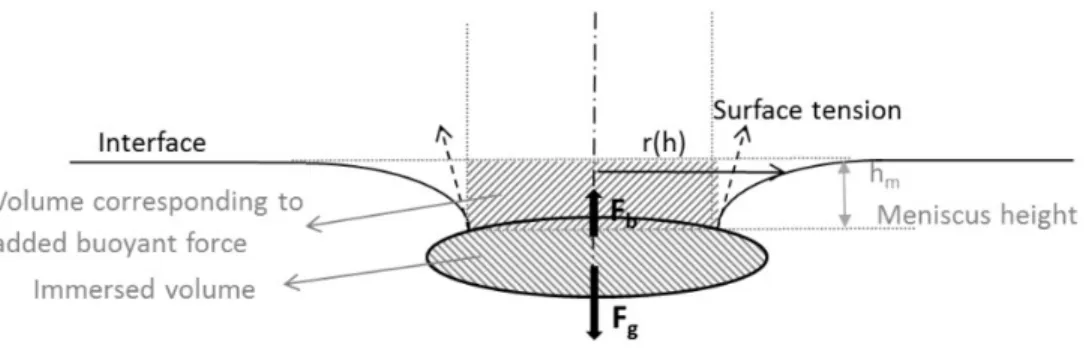
small objects (Figure 1). 52
53 54
Figure 1: Forces acting on a floating axisymmetric object 55
3
The surface tension may contribute to the flotation in two ways. The vertical component of the 57
surface tension acting along the triple line is influenced by the so-called contact angle of the 58
liquid surface at the triple line. The surface tension can aid the flotation but it can hinder it as 59
well, depending on the wetting characteristics of the liquid-solid system. The meniscus around a 60
floating object is also the result of the surface tension and it influences the hydrostatic pressure, 61
therefore the buoyant force acting on the object. 62
Meniscus height 63
The surface tension is the result of the cohesive forces between the molecules of a liquid. 64
Molecules on the surface lack neighbors on one side, so the cohesive forces act on the liquid 65
side only and pull the surface towards the bulk of the liquid. It leads to a curved surface, also 66
called meniscus. The connection between the curvature of the meniscus and the pressure 67
difference across the surface or interface is described by the Young-Laplace equation (Eq. 1). 68 ∆𝑝 = 𝛾 1 𝑅 + 1 𝑅 = 𝛾2𝐾 (1) 69 70 Δp: Laplace pressure 71 : surface tension 72
Rx, Ry radius of curvature in two perpendicular axes in the tangent plane to the surface.
73
K: mean surface curvature 74
The inclusion of the meniscus height in a flotation model can be done in various ways. The 75
simplest solution is to neglect the meniscus height altogether, and consider the buoyant force 76
corresponding to the volume of the object below the triple line [1] or below the undisturbed 77
surface [2]. It is a pragmatic solution, which results in a negligible inaccuracy for the flotation of 78
particles significantly smaller than the capillary length (Eq. (7)) of the interface, as is the case 79
with the flotation of individual smelter grade alumina particles on the surface of the electrolyte. 80
Solheim applied the meniscus height calculated beside a plane wall to determine the flotation 81
limit of disc-shaped alumina agglomerates on the bath-metal interface [3]. The meniscus height 82
around a cylinder approaches that around a plane wall as the radius increases, which makes this 83
estimation appropriate for large objects. The most precise method would be to solve the Young-84
Laplace equation. Singh used direct numerical simulation of the water-air interface to determine 85
the behavior of floating particles, and as he pointed out, the required computational capacity 86
increases unfeasibly when there are several objects on the surface [4]. 87
In this work the equation describing liquid surface around axisymmetric objects [5] was solved 88
numerically to obtain the meniscus height Eq. (2): 89 𝐾 = 𝑟 ′ (1 + 𝑟′ ) / − 𝑟′ (𝑏 + 𝑟)(1 + 𝑟′ ) / (2)
4 90
Where: 91
b: radius of axisymmetric object at the triple line 92
r=r(h): interface profile, (see Figure 1) 93
r’, r’’: first and second derivatives of r(h) 94
h: meniscus height/depth, axial (vertical) coordinate 95
From Eq. 1, the surface curvature can be expressed as a function of the capillary pressure, which 96
is proportional to the meniscus height (-h). Matlab ordinary differential equation solvers can 97
only solve fist order equations; therefore the second order equation was rewritten as an 98
equivalent system of first order equations. The meniscus height was in question; an initial value 99
was specified, then trial and error method was used to obtain the final result. 100
Angle of interface at triple line 101
The angle of the interface at the triple line is necessary to find the vertical component of the 102
surface tension, and also as a boundary condition for the Young-Laplace equation to determine 103
the meniscus height. For smooth, homogenous surfaces, the Young-Dupré equation shows the 104
connection between the interfacial energies and the equilibrium contact angle. If the floating 105
object has a smooth surface, the angle of the object at the triple line and the contact angle 106
determine the angle of the liquid surface Eq. (3) 107
𝛾 − 𝛾 = 𝛾 cos 𝛼 (3)
The contact angle (α) has a significant influence on the flotation. A large contact angle will 108
permit the floating object to descend deeper below the line of the undisturbed surface without 109
sinking than an object wetted by the liquid could. But that is not to say flotation of an object 110
denser than the liquid is not possible even if the contact angle defined by the Young-Dupre 111
equation would reach 0°, as the shape and surface quality of the solid would also influence the 112
angle of the interface at the contact line (δ) (Figure 2: Illustration for Gibbs extension to Young-113
Dupré law. 114
In the mathematical model, two different geometries were considered: spheres and cylinders 115
(round disks). The spherical objects were considered smooth, but the effect of roughness can be 116
investigated by increasing the apparent contact angle in the model. In case of circular disks, the 117
angle of the interface at the edge has a degree of freedom as specified by Gibbs [2] Eq. (4). 118
𝛼 < 𝛼 < 180 − 𝛽 + 𝛼 (4)
Where α0 is the static equilibrium contact angle and β is the angle of the corner of the solid body
119
as shown in Figure 2. 120
5 121
122
Figure 2: Illustration for Gibbs extension to Young-Dupré law 123
124
On rough or heterogeneous surfaces, the Young equation is only locally applicable, although the 125
Wenzel and the Cassie-Baxter equations offer estimations for the apparent contact angle (α) for 126
different wetted states. [5] 127
128
To determine the angle of the interface at the contact line, both the shape of the object and the 129
contact angle should be known, however it is often not the case. Maru’s approximation for 130
maximal radius of a floating spherical object is independent of the contact angle. His equation 131
has been used to calculate the flotation limit of solid alumina agglomerate on the bath-metal 132
interface. As the result, 7.5 mm was calculated as the critical diameter [6]. 133
Flotation in mineral industry 134
Particle flotation has been used in the mineral industry for more than a hundred years to 135
separate valuable ores from the waste. The ores are crushed, and then mixed in with water and 136
possibly other additives. Air is fed into the slurry and the rising bubbles collect and transport 137
certain minerals to the surface, as particles get attached to the interface of the bubbles [7]. 138
Most researchers in this field have a more practical than theoretical approach, focusing not on 139
the possibility but the probability of flotation, the particle retention. Flotation models can be 140
found, albeit sometimes crude and the bulk of the works is empiric [8] [9] [10]. Although there 141
are unarguably differences, it is worth pointing out that the anode gas forming in the electrolysis 142
cells also creates a current of bubbles in the electrolyte. This parallel might become even more 143
significant in the future with inert anode technology, as they work with saturated bath that 144
would promote the presence of undissolved alumina. 145
Flotation of alumina in the cryolitic bath, along the bath-metal interface 146
6
Generally, the analysis of the flotation conditions on the bath surface has not generated much 147
interest. Walker measured the density of alumina rafts and found that they can float even when 148
their density exceeds the density of the cryolitic bath [11]. The flotation of carbon particles on 149
the bath, and their interference with the measurement of the surface tension, noted by 150
Kucharic [12] is worth mentioning as the same issue was encountered by the authors of this 151
paper, and industrial cells are contaminated with carbon dust even more than experimental 152
setups. 153
The possibility of flotation of alumina agglomerates on the bath-metal interface is of more direct 154
importance to the industry. A flotation model of disc-shaped agglomerates has been presented 155
by Solheim [3], and a simple estimation for the flotation limit of spherical agglomerates by 156
Thonstad [6]. Both of them focused mainly on the possibility of an alumina particle layer on the 157
interface. They theorize that the alumina layer on the interface impedes mass transfer of 158
aluminum, therefore decreases the re-oxidation of the metal by the anode gas and increases 159
current efficiency. Solheim proved the possibility of alumina and cryolite precipitation on the 160
interface through theoretical investigation of bath chemistry [13], though he later pointed out 161
that Marangoni convection might clear the interface of those particles [3]. 162
Properties of alumina-bath system, input data for flotation model 163
The values of density, interfacial tension and contact angle are necessary for the calculation of 164
forces on the interface. The density of the electrolytic bath depends on its temperature and 165
composition. To maintain good separation between the bath and liquid aluminum, the latter 166
having a density of 2.3 g/cm3, the bath density is usually kept around 2.1 g/cm3 or below.
167
Several empirical equations are available and have been presented in well-known reference 168
books in the industry [14] [15] Eq. (5). 169 𝜌 𝑔 𝑐𝑚 = 2.64 − 0.0008(𝑡𝑒𝑚𝑝𝑒𝑟𝑎𝑡𝑢𝑟𝑒 𝑖𝑛 ℃) + 0.18 𝑤% 𝑁𝑎𝐹 𝑤%𝐴𝑙𝐹 − 0.008(𝑤% 𝐴𝑙 𝑂 ) + 0.005(𝑤% 𝐶𝑎𝐹 ) + 0.008(𝑤%𝑀𝑔𝐹 ) − 0.004(𝑤%𝐿𝑖𝐹) (5) 170
The above-mentioned values represent well the parameters of the experimental setup used in 171
the present work and shall be used in the calculations. 172
The surface tension of cryolitic melts has been measured by several research groups by pin 173
detachment method [16] or maximum bubble pressure methods [12]. Model equations were 174
fitted to the experimental data Eq.(6). The validity of these empirical equations is limited to a 175
certain temperature range where the experiments were conducted. As the alumina fed into the 176
bath tends to be several hundred degrees cooler than the bath itself, surface tension values at 177
low temperature hold particular interest in the flotation of alumina rafts. Beside measurements, 178
7
a theoretical approach to predict the surface tension of molten salt mixtures is also available 179 [17]. 180 𝛾 𝑚𝑁 𝑚 = 266.69 − 0.1257𝑡 − 4.754(𝑤%𝐴𝑙𝐹 ) + 1.546 ∙ 10 𝑤%𝐴𝑙𝐹 ∙ 𝑡 + 3.002 ∙ 10 ∙ 𝑤%𝐴𝑙𝐹 + 2.078 ∙ 10 ∙ 𝑤%𝐴𝑙𝐹 ∙ 𝑤%𝐶𝑎𝐹 ∙ 𝑡 + 2.702 ∙ 10 ∙ 𝑤%𝐴𝑙𝐹 ∙ 𝑤%𝐴𝑙 𝑂 ∙ 𝑡 − 3.507 ∙ 10 ∙ 𝑤%𝐶𝑎𝐹 ∙ 𝑤%𝐴𝑙 𝑂 ∙ 𝑡 (6) 181 182
where t is the temperature in Celsius. 183
The equation (Eq. 6) predicts the surface tension to be 145 mN/m, at the chemical composition 184
and the temperature of the bath, during our experiments [16]. For the bath-metal interfacial 185
tension, 450 mN/m was used in the calculations [18]. 186
For future reference, the capillary length (a), a scaling factor necessary to calculate surface 187
curvature, and interpreting dimensionless forms of the flotation model, is 2.6 mm at the upper 188
bath surface Eq. (7). 189
𝑎 = 𝛾
∆𝜌𝑔
(7)
190
The contact angle between alumina and aluminum on the BMI was measured by Utigard [20] 191
and was found to be between 150-170°. As the electrolytic bath dissolves alumina, it is expected 192
that alumina is wetted by the bath. However, the actual contact angle between these 193
substances has not been found in the literature. 194
Experimental
195
Setup 196
The high temperature experiments were conducted at the laboratory of the authors’ research 197
group, GRIPS, UQAC, in a carbon crucible. The free surface of the bath was 7.6 cm x 7.6 cm 198
square with rounded corners. The depth of the bath was 3.8 cm. The prepared bath contained 199
83% cryolite, 11.5% AlF3 and 5.5% CaF2. Due to impurities, the initial alumina content was 3%.
200
The rectangular carbon crucible was placed in the heated chamber of an electric kiln, and 201
heated from three sides. The thermocouple for the temperature control was placed under the 202
crucible. The insulated cover from the top was removed during experiments, and replaced 203
between tests so the temperature could stabilize. For longer experiments, to reduce the heat 204
loss, the opening was covered with a quartz plate between manipulations to be able to observe 205
the test object on the bath surface. The control temperature usually was set to 980 °C, which 206
8
decreased after the removal of the cover. Periodically a thermocouple was inserted in the bath 207
and it showed that the temperature stabilized 10°C below the control temperature. 208
209
Contact angle measurement 210
The contact angle is a necessary parameter to determine the conditions of flotation. As the 211
alumina-cryolitic bath contact angle has not been found in literature, it was necessary to obtain 212
it through experiments. The high temperature and corrosive nature of the bath renders visual 213
methods to determine contact angle nearly impossible. Another difficulty may rise from the low 214
superheat: bath would solidify in contact with insufficiently preheated alumina. Extended 215
contact between unsaturated bath and alumina leads to dissolution, changing the shape and 216
size of the alumina object. 217
The first attempts to measure the contact angle by the capillary rise method provided 218
inaccurate results. To improve precision, other tests with Wilhelmy method were prepared, 219
using the gravimetric system developed by GRIPS at UQAC [19]. 220
The gravimetric system was developed to analyze different aspects of the behavior of alumina in 221
the cryolitic bath (Figure 3). Different test objects were suspended above the cryolitic bath. The 222
samples were descended at a predetermined velocity into the bath while their apparent mass 223
was measured by a load cell. Both the position and the apparent mass were recorded 224
simultaneously. 225
226
Figure 3: Schema of gravimetric system 227
9 228
An alumina rod of ¼ inch diameter was suspended by nichrome wire above the bath surface, 229
preheated to avoid bath solidification upon insertion, then descended with a velocity of 0.5 230
mm/s, the position and resultant force logged at 1 second intervals. 231
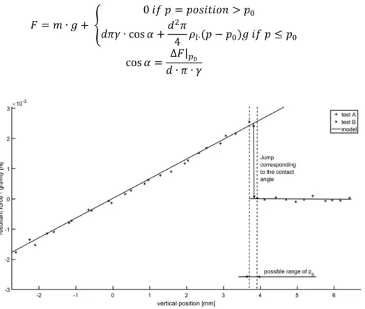
Before the test object touched the liquid surface (position larger than p0), the force corresponds
232
to its mass. When the object reaches the surface, the resultant force increases rapidly (ΔF), due 233
to the effect of the surface tension. With further descent in the liquid (position below p0) the
234
resultant force is decreased by the buoyant force. 235 𝐹 = 𝑚 ∙ 𝑔 + 0 𝑖𝑓 𝑝 = 𝑝𝑜𝑠𝑖𝑡𝑖𝑜𝑛 > 𝑝 𝑑𝜋𝛾 ∙ cos 𝛼 +𝑑 𝜋 4 𝜌∙(𝑝 − 𝑝 )𝑔 𝑖𝑓 𝑝 ≤ 𝑝 cos 𝛼 = ∆𝐹| 𝑑 ∙ 𝜋 ∙ 𝛾 (8) 236 237
Figure 4: Buoyant and surface tension forces acting on an alumina rod, 238
immersed into cryolitic bath 239
240
Theoretically, the contact angle can be calculated from the jump in the resultant force when the 241
rod first touches the surface (p0, position 0). However, as the data is not continuous, the
242
detection of the jump may be delayed by almost a full-time step. To decrease this uncertainty, 243
the results of two tests (A and B) were overlapped (Figure 4). Note that as we cannot produce 244
perfectly identical samples, both the resultant force and the zero position need to be adjusted. 245
Vertically, one set of results was shifted with the force corresponding with the difference 246
between the initial masses of the samples, while the horizontal shifting aligned the left side of 247
10
the diagram. This process did not only provide better visual representation, but the exact 248
position of zero was narrowed down significantly. There is a slight noise in the data, but the test 249
results correspond well to the model, and it narrows down the range of the contact angle to a 250
range of 29-34°. 251
Compressed alumina discs as artificial rafts 252
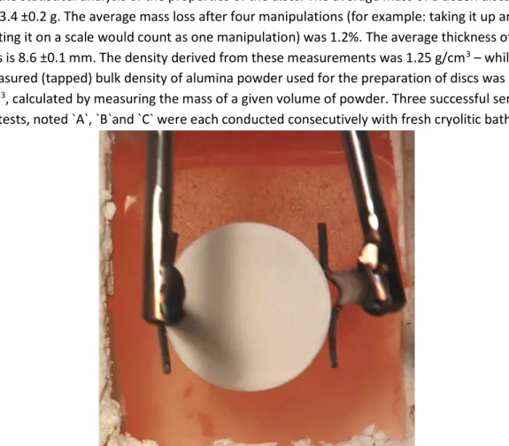
Primary alumina discs (with 40mm diameter and 8.6 mm thickness) were prepared using a 253
Struers Labo-Press 3 machine. 12.5 ml powder was fed into the machine chamber, and exposed 254
to 50 kN for 15 minutes which included a 3 minutes initial period where the powder was heated 255
to 180 °C. The produced discs were very fragile, they crumbled easily and some powder got lost 256
every time during handling them. For this reason, a separate batch of discs was prepared only 257
for the statistical analysis of the properties of the discs. The average mass of a dozen discs was 258
13.4 ±0.2 g. The average mass loss after four manipulations (for example: taking it up and 259
putting it on a scale would count as one manipulation) was 1.2%. The average thickness of the 260
discs is 8.6 ±0.1 mm. The density derived from these measurements was 1.25 g/cm3 – while the
261
measured (tapped) bulk density of alumina powder used for the preparation of discs was 1.03 262
g/cm3, calculated by measuring the mass of a given volume of powder. Three successful series of
263
tests, noted `A`, `B`and `C` were each conducted consecutively with fresh cryolitic bath. 264
265 266
Figure 5: Insertion of alumina disc onto the bath surface 267
268
The compressed discs were placed on the surface of cryolitic bath (Figure 5), and after a certain 269
period of time, they were recovered. The apparent density of the samples was estimated by 270
measuring the thickness and diameter of the recovered discs, assuming perfectly cylindrical 271
11
form, while in some cases, samples were covered with a silicon-based spray to obtain density 272
with Archimedes method; by weighing of the impermeable sample suspended in water and in 273
air. 274
Experiments on the bath-metal interface were attempted, but visual observation failed due to a 275
rapidly developing aluminum fog in the cryolite following the addition of the metal. The 276
formerly transparent cryolitic bath turned opaque, and the samples were hid from view under 277
the bath surface. While the gravimetric method may be applied in the future to examine the 278
flotation on the BMI, it is recommended to apply measures that help flatten the bath-metal 279
interface. 280
Mathematical model
281
The mathematical model was developed for two shapes: spheres and circular disks. The former 282
is used as a universal shape; it can represent a single alumina particle, or an agglomerate on the 283
bath-metal interface. The disk form holds more interest with small height-diameter ratio, as 284
alumina tends to spread on the bath surface, therefore a disc is a reasonably good 285
representation of an alumina raft. Theoretically, the same equation can be applied for large 286
height-diameter ratio, such as a rod, floating vertically. This, admittedly, is an unlikely, mostly 287
unstable scenario to occur naturally, and since it has no relevance for the studied phenomena 288
either, the height-diameter ratio in this study was limited to 1 and under. 289
The governing equations of flotation are presented below, along with the corresponding shapes 290
(Figure 6). 291
292 293
Figure 6: Geometries and corresponding force terms used in the present flotation model 294
12 Where ρs is the density of solid,
295
ρl is the density of liquid,
296
R is the radius of the sphere or the disc, respectively 297
H is the thickness of the disc 298
x is the relative immersion of the sphere: the vertical distance between the triple line and the 299
bottom of the sphere, in relation to its diameter 300
and hmen is the meniscus height.
301
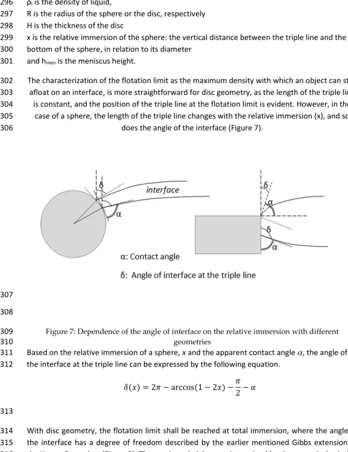
The characterization of the flotation limit as the maximum density with which an object can stay 302
afloat on an interface, is more straightforward for disc geometry, as the length of the triple line 303
is constant, and the position of the triple line at the flotation limit is evident. However, in the 304
case of a sphere, the length of the triple line changes with the relative immersion (x), and so 305
does the angle of the interface (Figure 7). 306
307 308
Figure 7: Dependence of the angle of interface on the relative immersion with different 309
geometries 310
Based on the relative immersion of a sphere, x and the apparent contact angle , the angle of 311
the interface at the triple line can be expressed by the following equation. 312
𝛿(𝑥) = 2𝜋 − arccos (1 − 2𝑥) −𝜋 2− 𝛼
(9)
313
With disc geometry, the flotation limit shall be reached at total immersion, where the angle of 314
the interface has a degree of freedom described by the earlier mentioned Gibbs extension to 315
the Young-Dupre law (Figure 2). The meniscus height was determined by the numerical solution 316
13
of the formerly presented equation (2). The following boundary conditions should apply, 317
assuming a single floating object on an otherwise undisturbed surface: 318 lim → 𝑟(ℎ) = ∞ 𝑑𝑟 𝑑ℎ = tan 𝛿 (10) 319
Due to the limitations of Matlab, and the fact that hmen was the sought parameter, a trial and
320
error method was applied, and the meniscus height gradually decreased until the solution 321
fulfilled (or rather, approached) the first boundary condition. Solutions for a few different 322
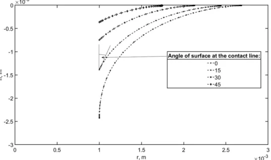
variables are presented below (Figure 8). 323
324
325
Figure 8: Numerical solution of differential equation, shape of meniscus 326
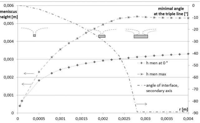
Regardless of the geometry of the object, the angle of the interface could potentially become 327
negative, so as the interface would bulge over the floating object. This does not hinder the 328
solution of the differential equation Eq. (2) (i.e. finding the shape of the interface) for larger 329
diameters, but as the radius of the triple line fell below the capillary length, the range of angles 330
for which acceptable solutions were found, became limited (Figure 9). 331
14 332
Figure 9: Dependence of meniscus height on radius and angle of surface 333
It should be noted however, that researchers who attempted solving the problem of meniscus 334
shape, did not succeed achieving negative interface angles with floating discs in reality, 335
supposedly due to instability [2]. It stands to reason, that a position with negative surface angle 336
would be unstable, and a slight tilt of the floating disc could swing the disc out of balance. As 337
one side of the disc gets closer to the surface, the angle of surface of the contact line at that side 338
gets closer to vertical, escalating the tilt. For this reason, the minimal angle of the surface for 339
discs in the model was limited to 0 degree (Figure 10). 340
341
Figure 10: Unstable position of a floating disc 342
While there is no possibility of stable floating position when the density of the solid exceeds the 343
density of the liquid, metastable states exist, where depending on the magnitude of the 344
disturbance, the degree of tilting or displacement from the equilibrium position, the floating 345
object might return to its original floating position, or sink. 346
15
Interpretation of results
347
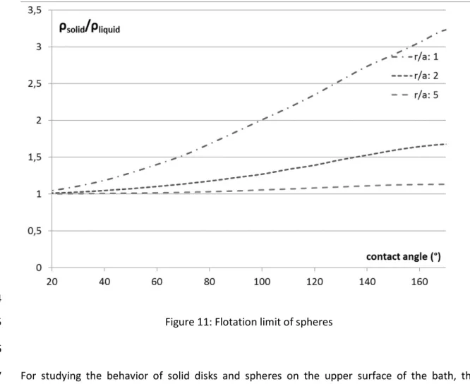
Firstly, the model results for flotation limit are presented in a general, dimensionless form 348
(Figure 11). The contact angle has an immense effect on the flotation limit of spheres. While in 349
case of perfect wetting, the density of a floating sphere could not exceed the density of the 350
liquid, the maximal density gradually increases with increasing contact angle, with a more rapid 351
rate in case of smaller dimensions (when the radius of the spherical object is at the same scale 352
as the capillary length). 353
354
Figure 11: Flotation limit of spheres 355
356
For studying the behavior of solid disks and spheres on the upper surface of the bath, the 357
flotation limit was calculated for 30° contact angle. The effect of the small contact angle is more 358
prominent for the flotation limit of spheres than for discs. Discs would always have a higher 359
flotation limit than spheres with the same volume and diameter; and as the height-diameter 360
ratio decreases, the discs get thinner, the curved surface`s contribution to the buoyant force 361
becomes more prominent, as can be seen in the increase of flotation limit with decreasing h/d 362
ratio (Figure 12). 363
16 364
Figure 12: Flotation limit on bath surface, contact angle: 30° 365
Alumina powder tends to spread on the bath surface due to its moisture content that 366
evaporates when it gets in contact with the molten electrolyte. Therefore, discs with small 367
thickness-diameter ratios hold the most interest. The bulk density of alumina powder is around 368
1 g/cm3, while the skeletal density of alpha alumina is almost 4 g/cm3. While cylindrical
369
agglomerates with large height-diameter ratio could be expected to float if they are only a few 370
mm in diameter, thin rafts could theoretically stay afloat easily. 371
17 372
373
Figure 13: Density limit of a fixed volume of alumina raft, assuming spreading to disc-shape 374
In industrial electrolysis cells a certain quantity of alumina powder is injected to the bath surface 375
at a time, usually between 0.5 and 2 kg, which corresponds to 0.5-2 l of volume. This powder 376
tends to spread on the available surface, limited by the anodes. With these considerations, the 377
density limit of flotation was calculated for disc-shaped alumina rafts (Figure 13). While the 378
density of larger rafts could only slightly exceed the density of the bath before sinking, with 379
smaller batch-sizes, the maximal density increases rapidly with the available surface for 380
spreading. 381
382
Comparison of model and experiments 383
The experiments proved that alumina discs can float on the surface of the cryolitic bath, even 384
when their density became larger than the density of the bath, therefore the surface tension 385
can play a role in the delayed dispersion of alumina in the bath. In the evaluation of the 386
experiments, the mathematical model of flotation is used reversibly. When modeling the 387
flotation, the maximal density of a floating object was calculated, based on its size and the 388
contact angle. For the experiments, the density and dimensions of the floating discs are known, 389
which, with the help of the mathematical model, provides the angle of the surface at the 390
contact line, at the moment the disc was removed from the bath – and that points to the 391
minimal contact angle (Figure 14). The discrepancy between the estimated and measured 392
density are due to the fact that the discs were covered with an uneven layer of frozen bath, 393
18
partly due to the removal process. As the estimated volume was based on the diameter and 394
thickness of the discs at their bottom corners, the volume was underestimated. While for the 395
measurement of the volume with Archimedes method, the total volume was measured, 396
including the added frozen bath, which adds to the volume, and, at that point of infiltration, 397
decreases the overall density. 398
While the contact angle between alumina and bath was measured to be around 30° using the 399
Wilhelmy method with an alumina rod, with the discs, only 10° was reached at best. This could 400
be explained by several factors relating to the realities of experimentation, such as the lack of a 401
well-defined, sharp edge of the discs, slight asymmetries in either the alumina discs or the 402
setup, and the continued exposure to disturbances, the convection in the bath, and 403
manipulations around the setup. 404
405
Figure 14: Density of samples, results from repeated experiments B and C 406
The video recordings of the experiments also show an influential factor, unaccounted for in the 407
mathematical model: the presence of carbon and other particles on the bath surface, originating 408
from the degradation of the carbon crucible and from the refractory walls. As the selected series 409
of images show (Figure 15), the surface starts creeping over the disc at the side that is clear of 410
scum. While the impurities on the left side hold the liquid surface at bay, the latter creeps upon 411
the disc on the right with an accelerating rate, causing its eventual submersion. 412
19 414
415
Figure 15: Compressed alumina disc, process of sinking; time after insertion marked (mm:ss) 416
417
Conclusions
418
The contact angle between alumina and cryolitic bath was measured, and a range of 29-34° was 419
determined. 420
A mathematical model was developed to investigate the conditions of static flotation of 421
axisymmetric objects on a liquid surface. Two geometry, disc and sphere, were considered. The 422
model was specifically applied to the parameters encountered in an aluminum electrolysis cell, 423
to analyze the flotation limit of alumina rafts, forming on the bath surface upon the injection of 424
alumina powder. The flotation limit was defined as the maximum density for a floating object of 425
a given size; alternatively, the flotation limit could be formulated as the maximum size of a 426
floating solid for a given density. It was shown how the expected shape, size and density of 427
20
alumina rafts and agglomerates could influence their flotation. Realistic sizes of alumina batches 428
were considered and the effect of spreading on the flotation was presented. 429
Besides a mathematical model, experiments with artificial alumina rafts were conducted on the 430
surface of cryolitic bath. While the theoretical flotation limit for compressed alumina discs has 431
not been reached in the experiments, it was only expected since perfect edges and symmetry is 432
unobtainable in reality, nevertheless, the contribution of the surface tension to the flotation was 433
shown. 434
The experiments brought attention to the influence of solid particles on the bath surface on 435
flotation which justifies further investigations. Also, an experimental study of the flotation on 436
the bath-metal interface has not been realized yet, future efforts will be needed to overcome 437
the experimental difficulties. 438
Acknowledgements
439
The authors would like to express their gratitude to Rio Tinto Aluminium and the Natural 440
Sciences and Engineering Research Council of Canada for their financial support. 441
Bibliography
442 443
[1] C. Kaszas, L. Kiss, S. Guerard and J.-F. Bilodeau: TMS Light Metals, 2015, pp. 639-644 444
[2] P. Singh and D. D. Joseph: Fluid Mechanics, 2005, vol. 530, pp. 31-80 445
[3] A. Solheim and S. Rolseth: TMS Light Metals, 2001, pp. 469-474 446
[4] Pushpendra Singh, Daniel D. Josep and Nadine Aubry: Soft Matter, 2010, no. 6, pp. 447
4310–4325 448
[5] Victor. M. Starov, Manuel G. Velarde, Clayton J. Radke: Wetting and Spreading 449
Dynamics, Surfactant Science Series vol 138, 1st ed., CRC Press, 2007.
450
[6] J. Thonstad and Y.-X. Liu: TMS Light Metals, 1981, pp. 303-312 451
[7] D. Bunyak: Mining History Journal, 2000, pp. 35-45 452
[8] B. Kowalczuk Przemyslaw and J. Drzymala: Colloids and Surfaces A: Physicochem. Eng. 453
Aspects, 2012, 393, pp. 81– 85. 454
[9] Daniel Chipfunhu, Massimiliano Zanin, Stephen Grano: Minerals Engineering, 2011, 24, pp. 455
50–57. 456
21
[10] P. B. Kowalczuk, O. Sahbaz and J. Drzymala: Minerals Engineering, 2011, 24, pp. 766– 457
771. 458
[11] David I.Walker: Alumina in aluminium smelting and its behaviour after addition to 459
cryolite-based electrolytes, PhD thesis, 1993, University of Toronto 460
[12] M. Kucharik and R. Vasiljev: Z. Naturforsch, 2006, no. 61a, pp. 389 – 398 461
[13] A. Solheim: TMS Light Metals, 2002, pp. 225-230 462
[14] J. Thonsta, Pavel Fellner, Geir Martin Haarberg, Jan Hives, Halvor Kvande, Asmund 463
Sterten: Aluminium Electrolysis - Fundamentals of the Hall-Heroult Process, 3rd ed.,
Aluminium-464
Verlag, Dusseldorf, 2001, pp. 87-114 465
[15] K. Grjotheim and H. Kvande, Introduction to Aluminium Electrolysis, 2nd ed.,
Aluminium-466
Verlag, Dusseldorf, 1993, pp. 60-85 467
[16] V. Danek, O. Patarak and T. Ostvold: Canadian Metallurgical Quarterly, 1995, vol. 34, no. 468
2, pp. 129-133 469
[17] M. Vermot Des Roches, Modèles de tension de surface pour les sels fondus et les 470
métaux liquides appliqués au procédé Hall-Héroult, master thesis, 2018, University of Montreal 471
[18] T. Utigard and J. M. Toguri, METALLURGICAL TRANSACTIONS B, 1985, Vol 16B, p 333-338 472
[19] J. Alari, L. Kiss, S. Poncsak, T. Roger: The Encyclopaedia of Research on Aluminium in 473
Quebec 2018, REGAL Students’ Day Aluminium Research Centre – REGAL, pp15 474