UNIVERSITÉ DE MONTRÉAL
LOW-PROFILE ANTENNAS FOR AIRCRAFT COMMUNICATION SYSTEMS
AMNA IKRAM
DÉPARTEMENT DE GÉNIE ÉLECTRIQUE ÉCOLE POLYTECHNIQUE DE MONTRÉAL
THÈSE PRÉSENTÉE EN VUE DE L’OBTENTION DU DIPLÔME DE PHILOSOPIAE DOCTOR
(GÉNIE ÉLECTRIQUE) DÉCEMBRE 2018
UNIVERSITÉ DE MONTRÉAL
ÉCOLE POLYTECHNIQUE DE MONTRÉAL
Cette thèse intitulée :
LOW-PROFILE ANTENNAS FOR AIRCRAFT COMMUNICATION SYSTEMS
présentée par: IKRAM Amna
en vue de l’obtention du diplôme de : Philosophiae Doctor a été dûment acceptée par le jury d’examen constitué de :
M. Wu Ke, Ph. D., président
M. LAURIN Jean-Jacques, Ph. D., membre et directeur de recherche M. AKYEL Cevdet, D. Sc., membre
DEDICATION
To my parents!
ACKNOWLEDGEMENTS
This dissertation could not have been finished successfully without the help and support of my research director Prof Jean-Jacques Laurin, technical staff, colleagues and my family. It is my great pleasure to acknowledge all those people who have given me guidance, help and encouragement throughout this journey.
First of all, I would like to take this opportunity to express my deepest appreciation and gratitude to my advisor Prof Laurin for believing in me and taking me into his research group as a PhD student. Without his support, constant supervision and strong technical guidance it would not have been possible to achieve my goals. To him, I wish to say, “Prof Laurin you are a wonderful person, supervisor, professor and researcher!”
I want to express my warm and sincere thanks to the technical support team for the fabrication and testing of prototypes. Mr. Jules Gauthier, for helping me with the test equipment. I would like to thank Mr. Traian Antonescu and Mr. Steve Dubé for fabricating my antenna precisely. I would like to thank Mr. Maxime Thibault for helping me in antenna measurements. Special thanks to Mr. Jean-Sebastien Décarie for his kindness and always been able to solve computer and simulation software related issues.
I would like to thank C. Forget and A. Cocozza from Centre de Recherché Industrielle du Québec (CRIQ) located in Montreal for near-field testing of antenna in EMC chamber. I want to thank Michael D. Hill from Trans-Tech Inc for providing magnetic material samples. I want to thank Thierry Maris from department of chemistry, Polytechnique de Montreal for doing X-ray diffraction (XRD) measurement of magnetic material.
I don’t want to miss chance to thank Mme Nathalie Lévesque, Mme Louise Clément, Mme Rachel Lortie for helping me with administrative issues during my studies. A special thanks to all my friends and colleagues at Polytechnique. I want to thank my husband Umar Shafique who has always been there to help me and overcome any challenge that I have confronted. I would like to extend my sincerest thanks to my sister Anila Asif without her support and encouragement, I doubt if I would have been able to complete this thesis successfully.
To my twinkle twinkle little star, my lovely son Asad who has always cheer me up and make me happy with his presence.
RÉSUMÉ
Dans les aéronefs, les antennes sont utilisées pour les communications ainsi que pour différents systèmes de navigation allant de 30 MHz à 4 GHz et plus. Le positionnement des antennes sur l'aéronef est crucial pour les systèmes avioniques. Les antennes de type « lame » (blade antennas) sont généralement utilisées dans l’aéronef pour divers systèmes de communication. L’antenne lame est essentiellement un monopole qui fait généralement autour d’un quart à un huitième de longueur d’onde et est encapsulée dans un radôme. À basse fréquence, la taille de la lame devient suffisamment grande pour introduire du bruit, augmenter la traînée aérodynamique de l'antenne et causer des dommages suite à une collision avec des équipements au sol lors de l’entretien et le service de l'aéronef. Par conséquent, et afin d’améliorer l'aérodynamisme des avions commerciaux efficaces, il devient nécessaire de disposer d'antennes conformes, à hauteur réduite et multifonctionnelles. Dans les avions commerciaux performants, l'aluminium est graduellement remplacé par un matériau composite à base de fibres de carbone. Ce matériau a l'avantage d’offrir une résistance meilleure que celle de l'aluminium pour un poids équivalent et aussi de réduire les coûts d’enretien et de réparation.
Dans cette thèse, quatre différents concepts d'antenne sont suggérés afin de réduire la hauteur d'une antenne, comparée aux antennes disponibles sur le marché pour des bandes de communications à Très Hautes Fréquences (VHF Comms 118-137 MHz), du système d'alerte de trafic et d'évitement de collision (TCAS 1.03-1.09 GHz) et du système d’équipement de mesure de distance (DME 0.96-1.22 GHz). Deux des concepts proposés sont basés sur le l’antenne en T avec des broches de court-circuit et des tronçons parasites pour rendre l’antenne à profil bas. Les deux autres concepts utilisent le chargement d’un monopole avec un matériau magnéto-diélectrique (MMD) et le chargement d’une antenne planaire avec un conducteur magnétique artificiel (CMA) pour rendre l’antenne à profil bas.
Le premier design consiste en une antenne bi-bande couvrant à la fois les bandes Comms TCAS et VHF. Une antenne VHF d'un dixième à l'échelle physique a été étudiée précédemment dans notre groupe de recherche, se basant sur le concept de monopole en T avec broches de court-circuit et tronçons parasites. Dans ce travail, l’antenne VHF est optimisée et modifiée pour une bande de
fréquence VHF à pleine échelle. Une plaque d'interface est ajoutée à la structure de l'antenne afin qu'elle puisse être facilement placée sur toute plate-forme appropriée pour d’éventuels tests ou utilisations futures. Une nouvelle approche est adoptée pour alimenter l’antenne TCAS placée sur l’antenne de la bande VHF. Ce concept présente l’avantage d’avoir une couverture bi-bande tout en utilisant l’empreinte d’une antenne à la surface de l’avion. La hauteur électrique de l'antenne TCAS est de 0.04λ et de 0.03λ pour la VHF, λ étant la longueur d'onde à la fréquence de fonctionnement la plus basse. La performance de l’antenne est mesurée lorsqu’elle est montée sur des plans de masse en aluminium et en composites. Un bon accord entre mesures et simulations est observé au niveau des propriétés de pertes de retour et de diagramme de rayonnement pour les deux types de plan de masse. En raison de la non disponibilité de systèmes de mesures de rayonnement en champ éloigné pour la bande VHF, des mesures de champ électrique en zone rapprochée sont effectuées dans une Chambre de Compatibilité Électromagnétique (CEM) du Centre de Recherche
Industrielle du Québec (CRIQ) et comparées à une simulation similaire à l’installation.
Le deuxième concept concerne la bande DME. Le prototype réalisé est mis à une échelle égale à 4 fois la fréquence de fonctionnement réelle. Dans cette antenne, une antenne micro-ruban planaire excite des motifs métalliques circulaires formant un CMA et une antenne à large bande conforme ayant une hauteur de 0.07λ et des caractéristiques de rayonnement similaires à celles de l'antenne monopole sont proposées. Cette conception est inspirée de la littérature mais est modifiée pour une bande passante fractionnelle plus grande (BPF) d’environ 30% par rapport à 6%. Il met également l’emphase sur les problèmes liés aux effets d’espaces d’air lors de la mise en place du matériau diélectrique sur le plan de masse.
Dans le troisième concept d'antenne pour la bande DME, une méthode bien connue de chargement de matériau a été utilisé. Un MMD est d'abord testé pour sa permittivité (𝜀𝑟) et sa perméabilité (𝜇𝑟) à l'aide d'un équipement de test de matériaux. Le MMD ayant des valeurs élevées de permittivité et de perméabilité relatives d’environ 10 a été placé de manière unique en tant qu’élément de chargement sur une antenne monopôle standard d’un quart de longueur d’onde. Le matériau est placé sur la pointe sous forme de disque et en bas sous forme d'anneau pour perturber les propriétés électriques et magnétiques du monopôle avec la permittivité et la perméabilité d'un MMD, respectivement. La hauteur du monopôle chargé est considérablement réduite de 29.5% tout en conservant de bonnes propriétés de rayonnement par rapport à un monopôle non chargé.
Le quatrième concept se rapporte à la bande DME. Une antenne cadre sectorielle couplée (CSLA) est utilisée à partir de la littérature, en tant qu'élément rayonnant et un nouveau concept de plan de masse rainuré est utilisé pour améliorer la directivité de l'antenne à l'horizon (𝜃 = 90 °), comme exigé par le système DME. La directivité à l'horizon est améliorée par le concept de boucle de courant magnétique équivalente en utilisant un plan de masse rainuré. À la fréquence de bande DME la plus basse, la hauteur électrique de l'antenne proposée est de 0.11 λ et son diagramme de rayonnement est similaire à celui d'un monopôle. Il présente toutefois l'avantage d'une réduction de hauteur de 0.25λ à 0.11λ. Comme les essais en soufflerie n’étaient pas disponibles, le calcul de la traînée aérodynamique du modèle proposé a été effectué à l’aide de formules empiriques et comparé à celui d’antenne DME de type lame standard.
Les quatre nouvelles conceptions d'antenne proposées dans cette thèse ont été simulées à l'aide d'un simulateur de structure haute fréquence (ANSYS HFSS), puis des prototypes ont été fabriqués et mesurés. La spécification du système requise pour chaque antenne proposée en termes de perte de retour, de diagramme de rayonnement et de bande passante est atteinte. La hauteur de chaque antenne est considérablement réduite, tout en conservant de bonnes caractéristiques de rayonnement similaires à celles des antennes lames utilisées sur le marché dans les quatre modèles, ce qui en fait de bons candidats pour les applications avioniques des aéronefs.
ABSTRACT
In aircrafts, antennas are used for communications as well as for different navigation systems ranging from 30 MHz to 4 GHz and more. The placement of antenna on the aircraft is critical to avionic system of an aircraft. Typically blade antennas have been used in the aircraft for various communication systems. Blade antenna is basically monopole of height usually about a quarter of a wavelength to one-eighth of a wavelength and encapsulated in a radome. At low frequency the size of blade becomes large enough to introduce the acoustic noise and increase the parasitic drag of the antenna and do mechanical damage and collision with ground equipment during aircraft maintenance and service. Hence to improve the aerodynamics of efficient commercial aircrafts there is a need of reduced height, conformal and multifunction antennas. In efficient commercial aircrafts aluminum has been replaced by composite material, other than being expensive it has advantage of such as weight reduction, more strength than aluminum and has fewer maintenance and repair costs.
In this dissertation four different antenna designs are proposed to reduce the height of an antenna as compared to commercially available antennas for Very High Frequency Communications (VHF Comms 118-137 MHz), Traffic Collision Avoidance System (TCAS 1.03-1.09 GHz) and Distance Measuring Equipment (DME 0.96-1.22 GHz) bands. Two of the designs proposed here are based on the concept of top-loaded antenna with shorting pins and parasitic stubs to make the antenna low-profile. The other two use the loading of a monopole with magneto-dielectric material (MDM) material and loading of a patch antenna with artificial magnetic conductor (AMC) to make the antenna low-profile.
The first design is a dual-band antenna covering both TCAS and VHF Comms bands. Previously in our research group a physically scaled one-tenth of VHF antenna has been investigated, which uses the concept of top-loaded monopole with shorting pins and parasitic stubs. In this work the VHF antenna has been optimized and modified for full-scaled VHF frequency band. An interface plate has been added to the antenna structure so that it can easily be placed on any platform suitable for future testing or use. A novel approach has been used to feed the TCAS antenna placed over the VHF band antenna. Such design has an advantage of having dual-band coverage while using footprint of one antenna on the surface of an aircraft. The electrical height for TCAS antenna is 0.04λ and for VHF its 0.03λ where λ is the wavelength at lowest frequency of operation. The
antenna performance has been measured for both aluminum and composite ground planes and good comparison has been seen in the return loss and radiation properties with both ground planes. Due to the unavailability of far field radiation measurements for VHF band, near electrical field measurements were done in Centre de Recherché Industrielle du Québec (CRIQ), electromagnetic compatibility (EMC) chamber and compared with the similar simulation setup.
The second design is for the DME band, but it is scaled to 4 times of the actual operating frequency. In this antenna a microstrip patch antenna excites the circular AMC cells and a conformal broadband antenna with height of 0.07λ and radiation characteristics similar to monopole antenna is proposed. This design is inspired by literature but has been modified for larger fractional bandwidth (FBW) of approximately 30% as compared to 6%. It also highlights issues related to the effects of air gaps while placing dielectric material on the ground plane.
In the third antenna design for DME band, a well-known concept of material loading has been used. The MDM is first tested for permittivity (𝜀𝑟) and permeability (𝜇𝑟) using Keysight material testing equipment. The MDM with high 𝜀𝑟 and 𝜇𝑟 values of approximately 10 has been uniquely placed as a loading element on a standard quarter wavelength monopole antenna. The material is placed at the tip as a disc and at the bottom as ring to disturb the electric and magnetic properties of monopole with the permittivity and permeability of MDM respectively. The height of loaded monopole is considerably reduced by 29.5% while keeping good radiation properties as compared to unloaded monopole.
The fourth design is for DME band. A coupled sectorial loop antenna (CSLA) is used from the literature, as a radiating element and a new concept of grooved ground plane is used to enhance the directivity of antenna at horizon (𝜃=90°) as required by the DME system. The directivity at horizon is improved by the equivalent magnetic current loop concept with the use of grooved ground plane. At the lowest frequency of DME band the electrical height of the proposed antenna is 0.11λ and it has a radiation pattern similar to that of a monopole, but it has the advantage of height reduction from 0.25λ to 0.11λ. As wind-tunnel testing wasn’t available, aerodynamics drag calculation of proposed model has been done using empirical formulas and compared with that of off-the-shelf DME blade antenna.
All four novel antenna designs proposed in this thesis have been simulated using high frequency structure simulator (ANSYS HFSS), fabricated and measured. The required system specification
for each proposed antenna in terms of return loss, radiation pattern and bandwidth has been achieved. The antenna height is considerably reduced while keeping good radiation characteristics similar to commercially used blade antenna in all the four models, which makes them good candidates for the aircraft avionics applications.
TABLE OF CONTENTS
DEDICATION ... III ACKNOWLEDGEMENTS ... IV RÉSUMÉ ... V ABSTRACT ... VIII TABLE OF CONTENTS ... XI LIST OF TABLES ... XV LIST OF FIGURES ... XVI LIST OF SYMBOLS AND ABBREVIATIONS... XXIV LIST OF APPENDICES ... XXVICHAPTER 1 INTRODUCTION ... 1
1.1 Aircraft antenna ... 1
1.2 Requirements for an aircraft antenna ... 2
1.3 Problems associated with aircraft antennas ... 3
1.4 Motivation and context for new antenna design ... 4
1.4.1 Objective and background ... 5
1.5 Contributions to research ... 5
1.6 Thesis outline ... 7
CHAPTER 2 LITERATURE REVIEW ... 8
2.1 TCAS system... 8
2.2 VHF system ... 9
2.3 DME system ... 10
2.4 Composite and aluminum aircraft ... 11
2.5.1 Blade antenna ... 12
2.6 Literature review for low-profile antenna ... 13
2.6.1 Small antenna ... 14
2.6.2 Antennas for aircraft applications ... 15
2.6.3 Techniques to make low-profile antenna ... 16
2.7 Conclusion ... 25
CHAPTER 3 DUAL-BAND ANTENNA ... 26
3.1 Functionality of the TCAS antenna ... 26
3.2 Commercially available TCAS antennas ... 27
3.3 Design of a low-profile TCAS antenna ... 27
3.3.1 Top-loaded monopole antenna ... 28
3.3.2 Top-loaded monopole antenna with shorting pins ... 29
3.3.3 Top-loaded monopole antenna with shorting pins and CPW ... 31
3.3.4 Microstrip line feed to the TCAS antenna ... 36
3.4 Fabrication and testing of the TCAS antenna ... 36
3.5 Functionality of aircraft VHF communication antennas ... 39
3.6 State-of-the-art technology-VHF ... 39
3.7 Previous design of scaled VHF antenna ... 40
3.7.1 Limitation to the scaled VHF antenna... 41
3.7.2 Design of the full-scaled VHF antenna ... 42
3.8 Need for a multiband antenna on an aircraft ... 50
3.9 Specification of a dual-band antenna ... 50
3.10 Design of dual-band antenna ... 51
3.12 Experimental characterization of the dual-band antenna ... 56
3.13 Near-field testing of the dual-band antenna ... 58
3.14 Conclusion ... 62
CHAPTER 4 SURFACE WAVE ANTENNA FOR DME APPLICATIONS ... 63
4.1 Functionality of DME antennas ... 63
4.2 Design of a DME surface wave antenna ... 63
4.2.1 Surface wave antenna ... 64
4.2.2 Grounded dielectric slab... 64
4.2.3 Probe-fed dielectric slab ... 65
4.2.4 Patch-fed dielectric slab ... 67
4.2.5 Patch loaded with perfect electric conductor (PEC) ... 68
4.2.6 Patch loaded with artificial magnetic conductor (AMC) ... 70
4.3 Fabrication of a SWA prototype ... 77
4.4 Testing of the SWA ... 79
4.4.1 S11 measurement ... 79
4.4.2 Radiation pattern measurement ... 82
4.5 Conclusion ... 87
CHAPTER 5 MAGNETO-DIELECTRIC MATERIAL LOADED MONOPOLE ANTENNA ………88
5.1 Material loading of antenna... 88
5.1.1 Dielectric loading ... 89
5.1.2 Magneto-dielectric materials ... 89
5.1.3 Benefits of using magneto dielectric materials ... 89
5.2 Measurement of MDM TTZ500 ... 91
5.4 Fabrication and measurement of a MDM loaded antenna ... 102
5.5 Conclusion ... 107
CHAPTER 6 COUPLED SECTORAL LOOP ANTENNA FOR DME APPLICATIONS . 108 6.1 Distance measuring equipment system (DME) ... 108
6.2 Why not blades? ... 109
6.3 Monopole antenna and its dependence on the ground plane ... 109
6.4 Concept of dual magnetic current loop antenna ... 110
6.5 Physical implementation of dual-loop concept ... 113
6.6 Design of horizontal grooved antenna ... 114
6.7 Fabrication of prototype and testing... 120
6.8 Matching of fabricated CSLA with grooved ground plane ... 122
6.9 Drag calculations for blade antenna and proposed antenna ... 124
6.10 CONCLUSIONS ... 128
CHAPTER 7 CONCLUSIONS AND FUTURE WORK ... 129
7.1 Summary of the Contributions ... 129
7.2 Future Work ... 133
7.3 Publications of research papers ... 134
7.3.1 Conference proceedings ... 134
7.3.2 Articles ... 134
BIBLIOGRAPHY ... 135
LIST OF TABLES
Table 2-1: TCAS antenna design specifications. ... 8
Table 2-2: VHF antenna design specifications. ... 9
Table 2-3: DME antenna design specifications... 11
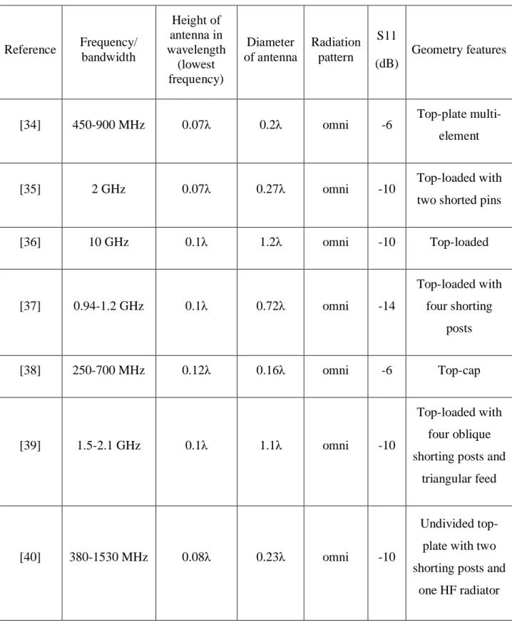
Table 2-4: Summary of different low-profile, top-loaded antennas in literature. ... 21
Table 3-1: TCAS antenna design specifications. ... 27
Table 3-2: VHF antenna design specifications. ... 39
Table 3-3: Dual-band antenna design specifications... 51
Table 4-1: Specifications of DME antenna. ... 63
Table 5-1: Specifications of DME antenna. ... 88
Table 5-2: Measured and data sheet values for relative permittivity and permeability. ... 94
Table 5-3: Measured fractional bandwidth. ... 104
Table 6-1:Specifications of DME system. ... 109
Table 7-1: Comparison of simulated and measured results of proposed designs. ... 131
Table 7-2: Comparison of theoretical upper bound of FBW and simulated FBW for proposed designs. ... 132
LIST OF FIGURES
Figure 1-1: Antenna placement on a passenger aircraft for various communication systems [1]. .. 1
Figure 1-2: Blade and whip antenna placed on an aircraft [5]. ... 3
Figure 2-1: DME navigation system. ... 10
Figure 2-2: Commercial blade antennas from Sensor Systems [21-23]... 12
Figure 2-3: A UHF blade antenna showing the complex circuitry on the printed circuit element – manufactured by Chelton [24]... 13
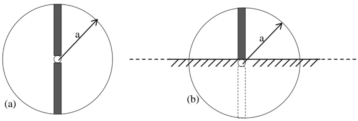
Figure 2-4: Definition of (a) Radius of a free-space dipole, (b) Radius of an imaginary sphere circumscribing the maximum dimension of a monopole on a ground plane. ... 14
Figure 2-5: Broadband multi-element antenna © 1981 IEEE [34]. ... 17
Figure 2-6: Cylindrical monopole antenna with shorted circular patch © 2001 IEEE [35]. ... 18
Figure 2-7: Top-loaded conical beam monopole antenna © 2011 IEEE [36]... 18
Figure 2-8: Top loaded monopole antenna with shorting posts © 2000 IEEE [37]. ... 19
Figure 2-9: Top-cap monopole antenna © 2004 IEEE [38]. ... 19
Figure 2-10: Fabricated prototype of top-loaded monopole antenna © 2009 IEEE [39]... 19
Figure 2-11: Modified Goubau antenna model © 2004 IEEE [40]. ... 20
Figure 2-12: Unbalanced short dipole placed on 10x10 PLGS © 2007 IEEE [42]. ... 22
Figure 2-13: Sectional sketch of antenna showing coaxial feed (left), annular excitation slot in ground plane (middle and material-coated monopole (right) © 2005 IEEE [51]. ... 24
Figure 3-1: Placement of TCAS and VHF antenna on the aircraft [60]. ... 26
Figure 3-2: TCAS antenna (a) Cobham 2442-88 [61], (b) Sensor Systems S65-5366735 [21]. ... 27
Figure 3-3: (a) Bare monopole with height ℎ on ground plane, (b) Bare monopole with height ℎ1 on ground plane, (c) Monopole with height ℎ1 and top disc. ... 29
Figure 3-4: Simulated impedance comparison of bare monopole and top-loaded monopole (a) Real part of impedance, (b) Imaginary part of impedance. ... 29
Figure 3-5: Simulated S11 of bare and top-loaded monopole antenna. ... 30
Figure 3-6: Top-loaded monopole with one shorting pin. ... 30
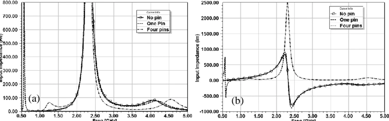
Figure 3-7: Impedance comparison of no pin, one pin and four pins (a) Real, (b) Imaginary. ... 31
Figure 3-8: Simulated TCAS antenna model with shorting pins and CPW. ... 32
Figure 3-9: Equivalent circuit of TCAS antenna. ... 32
Figure 3-10: S11 comparison of antenna after including the CPW. ... 33
Figure 3-11: Impedance of antenna with and without CPW. ... 33
Figure 3-12: TCAS antenna parameters. ... 34
Figure 3-13: Parametric study on CPW line length. ... 34
Figure 3-14: Parametric study on position of CPW line from the center ... 35
Figure 3-15: Parametric study on CPW line width. ... 35
Figure 3-16: TCAS antenna model (a) Top view, (b) Side view. ... 36
Figure 3-17: Simulated model of TCAS antenna with microstrip line (a) Top view, (b) Isometric view. ... 37
Figure 3-18: Fabricated prototype of TCAS antenna. ... 37
Figure 3-19: Simulated and measured S11 of TCAS antenna. ... 37
Figure 3-20: Realized gain of TCAS antenna both simulated and measured (a) Azimuthal (H) plane, (b) Elevation (E) plane. ... 38
Figure 3-21: VHF blade antenna Cobham 2448-88-00. ... 40
Figure 3-22: Model of one-tenth scaled VHF antenna. ... 40
Figure 3-23: Equivalent circuit of VHF antenna model. ... 41
Figure 3-24: Simulated and measured S11 for one-tenth scaled VHF antenna © 2011 IEEE [64]. ... 42
Figure 3-25: Full-scaled VHF antenna (all dimension x10 of Fig.3-22). ... 43
Figure 3-27: Simulated S11 with different plate thickness. ... 44
Figure 3-28: Simulated S11 with different plate thickness on smith chart. ... 44
Figure 3-29: Simulated S11 of full-scaled VHF antenna with 50 Ω coaxial feed. ... 45
Figure 3-30: Full-scaled VHF antenna with aluminum cylinder and 50 Ω coaxial feed. ... 46
Figure 3-31: Smith plot of comparison of S11 of full-scaled VHF antenna and modified feed antenna. ... 46
Figure 3-32: Comparison of S11 of full-scaled VHF antenna and modified feed antenna. ... 46
Figure 3-33: Parametric sweep of dia_oc. ... 47
Figure 3-34: Smith plot of parametric sweep of dia_oc. ... 47
Figure 3-35: S11 comparison of diameter of middle plate. ... 48
Figure 3-36: VHF antenna with interface plate. ... 49
Figure 3-37: S11 of VHF antenna with interface plate for various dia_oc. ... 49
Figure 3-38: Smith chart comparison of S11 for different values of dia_oc. ... 49
Figure 3-39: Full model of dual-band antenna. ... 52
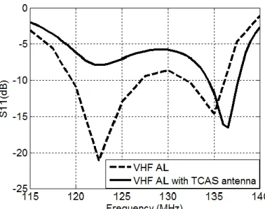
Figure 3-40: Comparison of simulated S11 of VHF antenna with aluminum ground and VHF antenna with TCAS antenna on aluminum ground. ... 52
Figure 3-41: Comparison of simulated S11 of TCAS with aluminum ground and TCAS antenna with VHF antenna on aluminum ground. ... 53
Figure 3-42: Step1: (a) 200 mm x 200 mm square interface plate with three shorting pins for VHF antenna, (b) Center pin for the VHF feed, (c) TCAS feed passing through one of the shorting pin, (d) holes for connecting the ground plane both aluminum or composite with the interface plate, (e) Nylon screws for holding the weight of middle plate. ... 54
Figure 3-43: Step2: (a) Middle plate of VHF antenna has been placed on the top of interface plate, (b) Plastic screws are placed at strategic points to support the top plate, (c) SMA connectors. ... 55
Figure 3-44: Step 3: (a) TCAS antenna, (b) Top plate of VHF antenna, (c) Middle plate of VHF
antenna, (d) Aluminum ground plane. ... 55
Figure 3-45: Outdoor testing of the dual-band antenna. ... 55
Figure 3-46 : Outdoor measurements (a) Aluminium ground connected to the antenna, (b) Composite ground connected to the antenna... 56
Figure 3-47: Simulated and measured S11 for VHF and TCAS for both aluminum (AL) and composite (Comp) ground. ... 57
Figure 3-48: Near-field measurement setup (a) Antenna under test, (b) Receiving antenna. ... 58
Figure 3-49: Near-field measurement setup in CRIQ (a) EMC chamber, (b) Operator room. ... 59
Figure 3-50: Simulation setup to analyze the one electric fields of the VHF antenna. ... 60
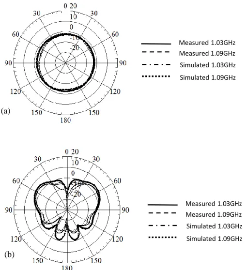
Figure 3-51: The comparison of simulated and measured electric fields at 𝜙=0°, 𝜙=45° and 𝜙=90° for both aluminum and composite ground plane for VHF band for 120 MHz, 123 MHz and 137 MHz. ... 61
Figure 4-1: Surface waves on a grounded dielectric material. ... 65
Figure 4-2: 50Ω coaxial probe feeding surface waves in a grounded dielectric substrate. ... 66
Figure 4-3: Simulated directivity of probe at horizon, 𝜃 = 89° for infinite ground plane. ... 66
Figure 4-4: Simulated directivity of probe at horizon, 𝜃 = 89° for infinite ground plane with different substrate diameter. ... 67
Figure 4-5: Center feed circular patch over infinite ground plane. ... 68
Figure 4-6: Simulated S11 of a patch antenna. ... 68
Figure 4-7: Center feed circular patch with dielectric superstrate. ... 69
Figure 4-8: Center feed circular patch with PEC at the top. ... 69
Figure 4-9: Simulated S11 comparison of patch, patch with superstrate, and patch with superstrate and PEC. ... 69
Figure 4-10: Mushroom type EBG structure... 71
Figure 4-12: Comparison of phase of reflection coefficient of square and circular AMC cells. ... 73
Figure 4-13: Simulation model of (a) Patch with PEC, (b) Patch with AMC... 74
Figure 4-14: Comparison of simulated impedance of patch with PEC and AMC (a) Real, (b) Imaginary impedance ... 74
Figure 4-15: Square AMC layer (a) 5x5, (b) 7x7, (c) 9x9. ... 74
Figure 4-16: Simulated S11 of square AMC layers. ... 75
Figure 4-17: Truncated AMC layer (a) 5x5, (b) 7x7, (c) 9x9. ... 75
Figure 4-18: Simulation of truncated AMC layer. ... 76
Figure 4-19: Simulation model of SWA (top view) (a) Patch only, (b) SWA, (c) Side view of SWA. ... 76
Figure 4-20: Simulated S11 for patch with superstrate, patch with PEC and patch with AMC. ... 77
Figure 4-21: Top view of simulated model for the fabricated prototype of SWA, (a) Middle sheet with patch and AMC layer, (b) Outer rings, (c) Complete SWA assembly. ... 78
Figure 4-22: Fabricated SWA. (a) Patch layer, (b) Patch and AMC layer, (c) Addition of the outer rings. ... 79
Figure 4-23: Comparison of simulated and measured S11 of patch antenna. ... 80
Figure 4-24: Comparison of simulated and measured SWA antenna. ... 81
Figure 4-25: Center feed circular patch with airgap=0.2 mm. ... 81
Figure 4-26: Comparison of S11 of patch antenna, simulated with air gap and measured. ... 81
Figure 4-27: Side view of SWA with airgap. ... 82
Figure 4-28: Comparison of simulated S11 for simulated SWA model with airgap and measured fabricated SWA. ... 82
Figure 4-29: Simulated realized gain (a) & (b) Azimuthal pattern of SWA, (c) & (d) Elevation pattern of SWA... 83
Figure 4-30: Measured realized gain (a) & (b) Azimuthal pattern of SWA, (c) & (d) Elevation pattern of SWA... 84
Figure 4-31: Simulated and measured S11 of quarter-wavelength monopole. ... 85
Figure 4-32: Comparison of simulated realized gain of SWA and monopole at 4.2 GHz (a) Azimuthal plane, (b) Elevation plane. ... 86
Figure 4-33: Comparison of measured realized gain of SWA and monopole at 4.2 GHz (a) Azimuthal plane, (b) Elevation plane. ... 86
Figure 5-1: Sample for dielectric testing. ... 91
Figure 5-2: Agilent network analyzer N5247A with high temperature test probe to measure complex permittivity. ... 92
Figure 5-3: Sample for magnetic testing. ... 92
Figure 5-4: Agilent impedance analyzer E4991A with test fixture 16454A to measure complex permeability. ... 93
Figure 5-5: Samples for testing the dielectric and magnetic properties of TTZ500. ... 93
Figure 5-6: Unloaded monopole on a metallic ground. ... 95
Figure 5-7: Electric and magnetic fields of monopole. ... 95
Figure 5-8: MDM disc placed at the top of monopole antenna. ... 96
Figure 5-9: Parametric sweep of diameter of disc 𝑑1. ... 96
Figure 5-10: MDM ring placed at the bottom of monopole antenna. ... 97
Figure 5-11: Parametric sweep of diameter of ring 𝑑. ... 97
Figure 5-12: MDM disc and ring placed on the monopole antenna... 98
Figure 5-13: Comparison of simulated S11 of monopole with disc, with ring and both ring and disc. ... 98
Figure 5-14: Comparison of simulation of MDM for both ring and disc and dielectric material for disc and magnetic material for ring. ... 99
Figure 5-15 Comparison of simulated S11 with magnetic loss tangent 0.1 and 0.5. ... 100
Figure 5-16: Simulated realized gain at 1.1 GHz for monopole, monopole with disc and monopole with both ring and disc (a) Azimuth (H), (b) Elevation (E). ... 101
Figure 5-17: Monopole antenna loaded with TTZ material and wrapped by styrofoam. ... 102 Figure 5-18: Comparison of simulated and measured S11. ... 103 Figure 5-19: Radiation pattern measurement in Satimo Starlab test setup. ... 105 Figure 5-20: Measured realized gain of loaded and unloaded monopole antenna. (a) azimuth plane, (b) vertical plane... 105 Figure 5-21: Comparison of measured efficiency of loaded and unloaded monopole antenna. .. 106 Figure 6-1 : Aircraft using DME communication system at different heights from the control
station. ... 108 Figure 6-2: (a) Slot in a ground plane equivalent to magnetic loop, (b) Electric dipole is dual .. 110 Figure 6-3: Two concentric loops of radius 𝑎 & b with magnetic currents 𝐼𝑚𝑎 and 𝐼𝑚𝑏. ... 111 Figure 6-4: Plot of directivity of two magnetic current loops with inner loop radius 𝑎 = 0.2 𝜆 and outer loop radius is 𝑏 = 0.4 𝜆. ... 112 Figure 6-5 : Realization of dual magnetic loop concept, CSLA acting as inner loop and placed 113 Figure 6-6: Simulation model of CSLA antenna on a finite ground plane. ... 114 Figure 6-7: Simulation model of proposed design CSLA over grooved ground plane. ... 115 Figure 6-8:Simulated realized gain at horizon (𝜃=90°) for different values of ℎ, 𝑑1 and 𝑑2. ... 116 Figure 6-9: Simulated S11 for different ℎ, 𝑑1 and 𝑑2. ... 116 Figure 6-10: Electric field magnitude in the vicinity of (a) CSLA only, (b) CSLA with grooved ground plane. ... 117 Figure 6-11: Comparison of simulated realized gain for CSLA, CSLA with grooved ground and quarter-wave monopole. ... 118 Figure 6-12 : Comparison of simulated realized gain both elevation and azimuth for (a) 1GHz, (b)
... 119 Figure 6-13:Fabricated prototype (a) CSLA (b) CSLA with grooved ground plane. ... 120 Figure 6-14: Comparison of S11 simulated and measured antenna. ... 121
Figure 6-15: Comparison of measured realized gain for CSLA, CSLA with grooved ground (without matching) and monopole. ... 121 Figure 6-16: Comparison of measured realized gain for CSLA, CSLA with grooved ground and monopole. ... 122 Figure 6-17: Passive circuit matching in ADS. ... 122 Figure 6-18: Matching of measured S11 of CSLA with grooved ground plane. ... 123 Figure 6-19:Improvement of realized gain with matching circuit. ... 124 Figure 6-20:Drag models for (a) Blade antenna (b) Proposed antenna. ... 126 Figure 6-21:Measured Drag coefficient of different shapes of objects [7]. ... 127 Figure A-1 : XRD of TTZ500 sample. ... 142
LIST OF SYMBOLS AND ABBREVIATIONS
AMC Artificial Magnetic Conductor ATC Air Traffic Control
AUT Antenna Under Test
CLAS Conformal Load Bearing Antenna Structure CRIQ Centre de Recherché Industrielle du Québec CSLA Coupled Sectorial Loop Antenna
DAB Digital Audio Broadcasting
DF Direction Finding
DME Distance Measuring Equipment
DO DME Operating
DVB-H Digital Video Broadcasting-Handheld EBG Electromagnetic Band gap
EMC Electromagnetic Compatibility EMI Electromagnetic Interference FAA Federal Aviation Administration FBW Fractional Bandwidth
GPS Global Positioning System
HF High Frequency
LAN Local Area Network LTE Long Term Evolution MDM Magneto-Dielectric Material PEC Perfect Electric Conductor PMC Perfect Magnetic Conductor
PLGS Patch Loaded Ground Slab RadAlt Radar Altimeter
RAs Resolution Advisories
RTCA Radio Technical Commission for Aeronautics SIW Substrate Integrated Waveguide
SWA Surface Wave Antenna TAs Traffic Advisories
TCAS Traffic Collision and Avoidance System T-DMB Terrestrial-Digital Multimedia Broadcasting TE Transverse Electric
TEM Transverse Electromagnetic
TM Transverse Magnetic
UAV Unmanned Aerial Vehicle UHF Ultra High Frequency UWB Ultra-Wideband VHF Very High Frequency
VOR Very high frequency Omni-directional Range VSWR Voltage Standing Wave Ratio
WWAN Wireless Wide Area Network XRD X-ray Diffraction
LIST OF APPENDICES
CHAPTER 1
INTRODUCTION
1.1 Aircraft antenna
In a wireless communication system, the antenna is one of the very important components. It provides an interface between the wireless electronics systems to the outside world. All antennas, regardless of their applications are characterized by common features such as operational frequency, Fractional Bandwidth (FBW), radiation pattern, Voltage Standing Wave Ratio (VSWR) or return loss (S11), efficiency, directivity, gain, polarization, etc. In aircrafts, antennas are used for communications as well as for different navigation systems ranging from 30 MHz to 4 GHz and more. These navigation systems provide a number of functions for the operation of the aircraft, such as Direction Finding (DF), Distance Measuring Equipment (DME), Global Positioning System (GPS), Microwave Landing System (MLS), Radar Altimeter (RadAlt) etc.
Figure 1-1 [1] lists different communication and navigation systems used by an aircraft along with respective antenna placement location. Large aircraft duplicate essential systems like Very High Frequency Communication (VHF Comms) system, Traffic Collision Avoidance System (TCAS) and Air Traffic Controller (ATC) system. They use more than one antenna for redundancy and safety reasons.
1.2 Requirements for an aircraft antenna
The antennas used in an aircraft system are required to meet minimal operational performance standards. Radio Technical Commission for Aeronautics (RTCA) has developed technical performance standards in close partnership with FAA. For example, for DME the standard is documented as DO-189 [2], for VHF band it is DO-186B [3] and for TCAS the standard is documented as DO-185B [4]. The compliance of DME, TCAS and VHF aircraft antenna to these standards ensure that the equipment will perform adequately for the given operation. The test requirements of DME antenna are stated below:
1. The antenna should be placed at the center of a flat circular ground plane with diameter of 1.2 m (1200 mm).
2. The antenna VSWR should be less than 2 for the DME frequency band.
3. The average radiation field strength of antenna in the azimuthal plane should be equal to radiation field strength of a matched resonant quarter-wavelength vertical monopole. 4. The difference between the maximum and minimum radiation field strength in the
azimuthal plane should not exceed 6 dB.
5. The elevation field strength of antenna should be equal or greater than that of a standard monopole antenna placed in the center of a ground plane at the same frequency with VSWR <1.2.
Similarly, the test requirements of a VHF antenna are following:
1. The antenna should be placed at the center of a flat square ground plane with size of 4 ft x 4 ft. (1219.2 mm x 1219.2 mm).
2. The antenna VSWR should be less than 3, for the VHF frequency band.
3. The average radiation field strength of antenna in the azimuthal plane should not be less than 6 dB as compared to radiation field strength of a matched resonant quarter-wavelength vertical monopole antenna.
4. The difference between the maximum and minimum radiation field strength in the azimuthal plane should not exceed 6 dB.
5. The elevation field strength of antenna should be equal or greater than that of a standard monopole antenna placed in the center of a ground plane at the same frequency with VSWR <1.2.
In general, the aircraft antenna requirements for various communication and navigation systems are listed as following:
1. Antenna location and placement: It is very important to establish the location of an antenna to be used in avionic systems as it can alter the stringent aerodynamic design requirements of the aircraft.
2. Dimensions: Size and weight are important factors that must be considered when selecting an antenna for a particular application. Size and weight also restrict the locations where the antenna can be installed.
3. Reliability: The candidate antenna must be capable of withstanding prolonged exposure to harsh environment conditions during the aircraft operation.
4. Maintenance: An antenna should be designed such that it requires a minimal repair and replacement time if it fails to operate.
1.3 Problems associated with aircraft antennas
Currently, large airplanes rely on blade and whip antennas as shown in Figure 1-21 [5] which are
highly visible, obtrusive and prone to damages. Blade antenna is a quarter-wavelength monopole antenna encapsulated in a radome. Some of the problems associated with currently employed aircraft antennas are as follows:
Figure 1-2: Blade and whip antenna placed on an aircraft [5].
1 Permission granted for the use of image.
Size and maintenance: In aircraft, for the aerodynamics and the mechanical stability, external antennas are a sensitive factor [6] . When the frequency of operation is low, the wavelength becomes large which makes the physical antenna size prohibitively large for most applications and unacceptable for platforms such as airplanes. A large external antenna has a greater tendency to collide and get damage with the ground equipment especially during aircraft maintenance and service.
Aerodynamics drag: During flight, airstream flows around an antenna. The physical interaction of the antenna with the air medium around causes an aerodynamics drag and generates aerodynamics noise [7]. The improper placement of antenna, additional weight and size of an aircraft antenna can increase the aerodynamics drag, which negatively effects the flying ability of an aircraft, such as increasing fuel consumption which eventually puts limitation on the speed of aircraft.
1.4 Motivation and context for new antenna design
There has been a great interest in the research and development of next generation energy efficient aircraft and avionics systems. The Canadian aerospace industry with the support of government of Canada is working on projects to improve aircraft operations, aircraft noise reduction and on additional topics targeted towards the development of greener aircraft for future. These projects also include work on composite materials i.e. to investigate materials that can be developed by reusing uncured aerospace grade pre-impregnated materials. All these activities mentioned above are a part of the green aviation research and development network (GARDN) [8] projects.
The work presented in this dissertation is a part of two academia-industry projects. The first project is partnered with École Polytechnique de Montreal (POLY), École de Technologie Supérieure (ETS), Concordia University, Bombardier Aerospace (BA) and MacDonald Dettwiler and Associates (MDA Corporation). The main contribution to the project is to make low-profile DME band antenna. The second project is Electromagnetic Platform for lightweight Integration/Installation of electrical systems in Composite Electrical Aircraft (EPICEA) and the collaborators are from Canada and europe, Axessim (France), Bombardier Aerospace (BA), École Polytechnique de Montreal (POLY), Ingegnerai dei sistemi (Italy) and Onera (France). Whereas, in this project, one of the objectives is to design low-profile dual-band (VHF & TCAS) antenna for aircraft communication system, which is a major contribution of this dissertation.
1.4.1 Objective and background
The objective of this dissertation is to design low-profile, conformal and multifunctional antennas that can work for both aluminum and energy efficient composite planes and can help to improve aerodynamics properties of commercial aircrafts. The following discussion explains the challenges and advantages of this work.
By making the antenna low-profile, it come very close to the metal body of an aircraft. Reducing the height of an antenna degrades its operational performance such as return loss, operating bandwidth and radiation pattern [9] .Therefore, it is required to investigate new designs, techniques and materials for low-profile antennas that can advantageously possess good radiation characteristics.
As mentioned earlier poor antenna placement can degrade the flying qualities of an aircraft and impact the performance of the avionics system. The compact and conformal antenna helps to find an installation location within the boundary layer especially if the antenna is added after the aircraft shape was frozen, i.e. normally a case where an additional installation or an upgrade to the aircraft electronics communication system is performed. A boundary layer is defined as a very thin layer of air flowing on the surface of aircraft. It gives an effective shape to any surface, which is slightly different from the actual physical shape. The details of the flow within the boundary layer are very important to understand the skin friction drag of an object. As any object protruding outside the boundary layer can produce a large drag force on the aircraft and cause turbulence [10].
The main advantage of combining two or more functions in one antenna results in the reduction of the total number of antennas required on an aircraft. This helps to minimize the overall aerodynamic drag, reduce number of service repairs or replacements due to corrosion and foreign object damage and reduce the number of structural holes needed to install the antenna. However, if a multifunctional antenna fails it can cause failure of more than one service thus additional measures are required to maintain reliability.
1.5 Contributions to research
This dissertation aims to design aircraft antennas, in compliance to the specific bands of communication and navigation systems used in an aircraft. Most of the research in this area is within the industry and commercially available antennas are usually blade antenna. Below are the
contributions made in this dissertation in the area of the aircraft antenna design. These novel, low-profile proposed designs are optimized, simulated, fabricated and tested. Both simulated and measured results are presented, which are in close agreement to each other and to the system requirements.
1. For the first time a dual-band antenna that covers both VHF Comms and TCAS band is presented. This antenna uses two separate antenna feeds and can be simultaneously used for both VHF and TCAS systems. The impedance matching and radiation characteristics of this antenna meet the system specifications and the presence of VHF antenna has minimal impact on the performance of TCAS antenna or vice-versa. The measured FBW of TCAS antenna is 5.6% and for VHF antenna its 14.9%. The height of TCAS and VHF Comms is 0.04λ and 0.03λ, where λ is the free space wavelength at lowest operating frequency of TCAS and VHF respectively. An interface plate has been integrated in the design for an easy assembly on any platform. The antenna performance was tested with both aluminum and composite ground planes to see the compatibility with both types of platforms.
2. A surface wave antenna (SWA), physically scaled by a factor of one-fourth for DME operating band is proposed. The antenna has been investigated for broad bandwidth by loading the patch antenna with circular artificial magnetic conductor (AMC) cells. The proposed design has 31% FBW (simulated). The height of antenna is 0.07λ and it shows radiation characteristics similar to those of a vertical monopole antenna.
3. A magneto-dielectric material (MDM) is used on a monopole at strategic positions to lower the resonant frequency. Without compromising the bandwidth of the antenna, the antenna height is reduced by 29%. The average measured efficiency of the antenna is ~ 60% for the DME band due to lossy nature of magnetic material.
4. For the DME band, a novel grooved ground plane is proposed with a well-known Coupled sectorial loop antenna (CSLA) [11]. The grooved ground plane is placed underneath the CSLA and by using the concept of dual loop antenna, maximum radiation at horizon is generated, which is one of the system requirements for DME band antenna. The drag coefficient for the proposed design is calculated by using empirical formula to get an estimate while comparing with a state-of-art blade antenna.
1.6 Thesis outline
In this dissertation four different designs of low-profile aircraft antennas for three different communication systems (VHF Comms, TCAS, and DME) are proposed. The outline of thesis is as follows.
In Chapter 2, general theory, state-of-art antennas and literature review is provided. A dual-band antenna for VHF Comms and TCAS system has been discussed in Chapter 3. Chapter 4 explains the design of SWA for DME band. Chapter 5 includes the discussion about the use of MDM for reducing the height of monopole antenna for DME band. Chapter 6 is the design of DME antenna with maximum directivity at horizon by using grooved ground plane and estimates the drag for the proposed design. Chapter 7 summarizes the thesis work with concise conclusion and gives some directions for the future research.
CHAPTER 2
LITERATURE REVIEW
This chapter covers the basic theory about aircraft communication systems, their working principles and state-of-the-art antennas currently used on aircraft. There is also a discussion about the advantages and disadvantages of composite and aluminum aircraft. This is followed by the literature review of aircraft antennas and the theory and techniques used in the design of four different proposed antennas.
2.1 TCAS system
Any passenger and cargo aircraft with a seating capacity of 10 or more are required to use TCAS navigation system as mandated by the Federal Aviation Administration (FAA) [12]. TCAS is an airborne system, which operates by interrogating the transponder of an approaching aircraft. This system helps the pilot to determine the presence of near-by aircrafts to avoid mid-air collisions. The distance between the aircrafts, which is defined as the range is determined from the time required to receive the reply, and the altitude is extracted from the information encoded within the reply signal. In a complete TCAS system, a pair of directional and omnidirectional antennas is used. The directional antenna determines the bearing to the approaching aircraft and an omnidirectional antenna yields only the range and altitude of an intruding, near-by aircraft [13]. However complete TCAS system is not explored here instead only an omnidirectional antenna is considered. The design specifications of omnidirectional TCAS antenna are given in Table 2-1. TCAS operates at two frequencies, 1.03 GHz is used for transmission i.e. to interrogate and 1.09 GHz frequency is to receive the transponders reply. This system is not intended to replace the
Table 2-1: TCAS antenna design specifications. Frequency 1.03 – 1.09 GHz Bandwidth 5.6% VSWR / S11 <2 / -10 dB Radiation Pattern Omnidirectional Polarization Vertical
existing ground-based air traffic control (ATC) system. However, TCAS augments the ATC capabilities and reduce its work load and thus improve the overall level of flying safety. The latest version of TCAS is TCAS-II, which offers pilot aural and visual warnings, as well as resolution advisories (RA) [14]. These traffic advisories (TAs) help the pilot to perform visual search for the intruding aircraft and also prepare the pilot for a potential maneuver using resolution advisories (RAs). TCAS-II helps to avoid mid-air collision by establishing communication to other aircraft and asking one aircraft to climb up and the other to descend.
2.2 VHF system
Air traffic controller uses the VHF communication system for its operation. VHF airband covers 108 MHz to 156 MHz, where Very high frequency Omnidirectional Range (VOR) is between 108 MHz to 118 MHz and VHF Comms has a frequency band of 118 MHz to 137 MHz. In this dissertation VHF Comms will be discussed and going forward VHF Comms will be written as VHF.VHF system is employed in all types of aircraft. This allows the pilot to request information and landing instructions from air traffic control centers and the control towers. For redundancy, two or more VHF antennas are installed on an aircraft [15]. They are usually installed along the lower and upper fuselage as shown previously in Figure 1-1. The location of the receiving station is not always the same or known, therefore the signal is transmitted in all directions using an omnidirectional antenna with a vertical polarization. Due to the nature of radio-wave propagation at VHF frequencies, the system is limited to line-of-sight distances. One advantage of VHF communication is that the transmitted signals are often less distorted by static or other interferences. Table 2-2 lists the design specification of a VHF antenna.
Table 2-2: VHF antenna design specifications. Frequency 118 – 137 MHz Bandwidth 15.7% VSWR / S11 <3 / -6 dB Radiation Pattern Omnidirectional Polarization Vertical
2.3 DME system
DME navigation system is used to track the nearest ground station ahead on the route during the flight. DME antenna is usually installed at lower forward fuselage. This system continuously displays information about the aircraft’s distance from the ground station. This is determined via sending two communication signal (pulses) from the aircraft to the nearest ground station ahead and once these pulses are received at the ground station, the ground station in return transmits the paired pulses toward the aircraft and the distance is calculated by the on-board DME transceiver module. As shown in Figure 2-1 the distance (slant range) changes with the height of the aircraft. Therefore, it is required to have maximum directivity of the DME antenna for 𝜃 above 60° to 90° depending upon the height of the aircraft. The DME antenna needs to be compliant with DO-189 standard as explained in Chapter 1. The specification for DME antenna is given in Table 2-3.
Figure 2-1: DME navigation system. 𝜃 = 0∘
𝜃 = 90∘
Interrogation signal
Table 2-3: DME antenna design specifications.
Frequency 0.96 – 1.22 GHz
Bandwidth 23%
VSWR / S11 <2 / -10 dB
Radiation
Pattern Omnidirectional with max directivity at horizon
Polarization Vertical
2.4 Composite and aluminum aircraft
For most of the antennas placed on the aircraft, the skin of the aircraft works as a ground surface. Although the aircraft fuselage is cylindrical, the surface is usually very large and acts like a flat ground plane for an antenna. Hence the material with which the ground plane is made up of is significantly important for the antennas attached to it. In the past, aluminum was solely used to make the aircraft body but in last few years, composite aircraft has gained markets attention and is a replacement to the aluminum material. The main advantage of using composite material for an aircraft is the weight reduction and improved material strength as compared to aluminum material. Composite materials are mechanically stronger than aluminum, for equal weight, and can provide smooth finish on to the surface. The aircraft shows a better fuel economy, if weight is reduced which is possible with the use of composite materials. Composite material are more resistant to corrosion as compared to aluminum and therefore have low maintenance and repair cost associated to them [16]. For the case of aluminum body if a damage such as, dent or puncture happens, it can be repaired and can maintain its mechanical properties, however for such a damage to a composite material, requires the whole entire pieces to be replaced [17]. The composite material does not break easily as compared to aluminum, which can easily bend and dent after the damage. So, it is harder to find the internal structural damages in composite. Advancements to composites material technology has enabled to engineer high-temperature-resistant composite materials that can be used for high performance economical aircraft [18]. Unlike aluminum, the reduced conductivity of composite structure do not make them a good candidate for electromagnetic shielding such as
in-case of lightning strike [17]. Composite materials are expensive due to complex fabrication process. Efficient planes like Boeing's 787 Dreamliner and Airbus's A350 are made up of more than 50% of lightweight carbon fiber composites [19]. In an aircraft manufactured by using composite materials, antenna grounding is performed by using an aluminum sheet under the antenna and feed [20].
2.5 State-of-the-art antennas for aircraft communications
Aircraft antennas are used in both commercial and military aircrafts. Companies like Sensor systems, Honeywell, EDO Corp, Chelton and Rockwell Collins, manufacture these blades and whip type antennas.
2.5.1 Blade antenna
The most common type of antenna used in an aircraft for TCAS, DME and VHF systems is a blade antenna. Figure 2-2 displays examples of a blade antenna used in an aircraft [21-23]. A blade antenna is primarily a monopole encapsulated in a covering. Covering serves to protect the antenna form external environmental damage as well as its shape provide aerodynamic properties as needed by the aircraft. The blades can have several octaves of bandwidth and shaped in a way to deliver broadband performance.
Figure 2-2: Commercial blade antennas from Sensor Systems [21-23]. DME Sensor Systems
S65-5366-7L, height 2.2in
VHF Sensor Systems S65-8280-10, height=11.85in TCAS Sensor Systems
S65-5366-735, height 2.45in (a)
(a)
(c) (b)
Figure 2-3: A UHF blade antenna showing the complex circuitry on the printed circuit element – manufactured by Chelton [24].
A passive blade can be used as an active antenna and its bandwidth performance can be improved by using a tuning circuit. An active UHF (225- 400 MHz) antenna is shown in Figure 2-3 2 [24].
As previously discussed in Chapter 1, at low frequencies, the size of the quarter wavelength blade becomes significantly large enough that it can introduce acoustic noise, increase the parasitic drag of the antenna and be prone to mechanical damage and collision during aircraft maintenance and service. One of the best possible way a blade antenna could be used advantageously without introducing extra drag is when placed at vertical or horizontal stabilizer or winglets, (winglet is a wing tip on the wings of an aircraft) [25].
2.6 Literature review for low-profile antenna
Study and design of low-profile antenna has always been actively explored at industrial research platform. The increase in the volume of on-board communication system and compact design requirements has made it a challenging research topic for the aircraft communication manufacturing industry. The literature reviewed in this section begins with the discussion about the fundamentals of a small antenna. Further, section 2.6.2 gives the overview of research work
2 Permission granted from Wiley.
conducted relevant to low-profile aircraft antennas and section 2.6.3 review the techniques used in the antenna designs proposed in this dissertation.
2.6.1 Small antenna
Defining the size of an antenna small has always been an interesting question. The definition of a small antenna can be somewhat ambiguous. However, if the size or volume of antenna including any ground plane image is less than𝜆4, 𝜆8 or 10𝜆, it is considered as a small antenna. Wheeler defined the small antenna as one, whose maximum dimension is a fraction of one radiansphere [26], where radiansphere is a spherical region of radius 2𝜋𝜆 around an antenna. The size or volume of a small antenna can be defined mathematically using the product of free space wavenumber (𝑘) and radius of a sphere circumscribing the maximum dimension of antenna (𝑎) as shown in Figure 2-4 (a). Where 𝑘, is given as 𝑘 =2𝜋𝜆. If the size of the ground plane is significantly large and the impedance of antenna remains the same even if placed on an infinite ground plane, then the size of the ground plane is not required to be included in the definition of 𝑎 as shown in Figure 2-4 (b). According to Wheeler, for an antenna size to be considered small the product of 𝑘𝑎 must be less than or equal to 0.5 i.e. 𝑘𝑎 ≤ 0.5. In case of standard monopole of quarter-wavelength height, 𝑘𝑎 is equal to 1.57.
Figure 2-4: Definition of (a) Radius of a free-space dipole, (b) Radius of an imaginary sphere circumscribing the maximum dimension of a monopole on a ground plane.
(a) (b)
𝑘𝑎 =2𝜋 𝜆 × 𝜆 4= 𝜋 2 = 1.57
Which implies that a standard monopole of quarter-wavelength height does not qualify to be a small antenna. In order for a monopole to qualify as a small antenna the maximum length of the monopole placed over infinite ground plane has to be approximately less than 𝜆
12.5 𝑜𝑟 0.08 𝜆. After
Wheeler, L. J. Chu, has defined fundamental limits and the parameter trade-off for the size of the antenna versus frequency of operation, matched bandwidth and gain [9]. The fractional bandwidth for matched VSWR/S11 is defined as 𝐹𝐵𝑊 =𝑤+−𝑤−
𝑤0 where 𝑤+ 𝑎𝑛𝑑 𝑤− are the frequencies above
and below the center frequency 𝑤0 . The upper bound of FBW for small antennas is given by equation (2-1) [27], where 𝑠 is the VSWR and 𝜂 is antenna efficiency.
𝐹𝐵𝑊𝑢𝑏 =1 𝜂[ 1 𝑘𝑎+ 1 (𝑘𝑎)3] −1𝑠 − 1 √𝑠 (2-1)
Where the quantity in brackets is the quality factor given by 𝑄 =𝑘𝑎1 +(𝑘𝑎)1 3. For small antennas, the product of bandwidth and efficiency is inversely proportional to 𝑄 and it is usually high. High quality factor means the ratio of energy stored in the antenna to the total power (radiated and dissipated) is high.
2.6.2 Antennas for aircraft applications
Designing low-profile aircraft antenna is challenging, especially when meeting the requirements of bandwidth, matching, and radiation characteristics. Following literature review shows that most of the designs compromise on one or the other factors as listed before.
A wide band omnidirectional antenna for VHF/UHF band is presented in [28]. The antenna is composed of a broadband gradually tapered exciter placed between two metallic sheets. It is matched for S11<-10 dB for a broad frequency band of 470 MHz to 6 GHz. The height of antenna is 0.094λ at the lowest operating frequency but the radiation pattern shows many ripples in the azimuthal plane due to the shape of the exciter.
A conical antenna radiator is loaded with capacitive disc and connected with parallel shorting post is presented in [29]. This antenna has a radiation pattern similar to a monopole for frequency 500 MHz to 1000 MHz. The antenna dimensions are 0.25λ 𝑥 1λ 𝑥 1λ, whereas the height is comparable to a standard monopole and becomes large for low frequencies and thus does not qualify to be a low-profile antenna.
A conformal load-bearing antenna structure (CLAS) is proposed in [30] for UHF and TCAS systems. It consists of a log-periodic antenna covered with magneto-dielectric material. The antenna is made of multilayered structure to reduce its size and weight. The height is approximately 0.02λ at the lowest frequency 200 MHz and the VSWR is less than 3.5 for 200 MHz to 400 MHz. The VSWR achieved in this design is above the specifications of UHF antenna system.
A very thin, Substrate Integrated Waveguide (SIW) antenna designed for C band (4.78-4.88 GHz), with bandwidth of 100 MHz is presented in [31]. The radiation pattern of this antenna is highly directional and is employed for a missile communication system.
In [32] a monopole antenna matched for frequency band of 112 MHz to 130 MHz is proposed. The antenna does not use any matching circuit. The height of antenna is 68 cm which is 0.25λ for lowest operating frequency. This antenna has less bandwidth and the height is comparable to that of a standard monopole antenna.
A monopole antenna coated with magneto-dielectric material is presented in [33] for High frequency (HF) applications. The electrical size of antenna is reduced by uniformly placing metallic posts around it. The antenna height is only reduced by 10% as compared to bare monopole for a resonant frequency of 27 MHz with a very narrow bandwidth. The literature review presented above covers only a small sample showing typical designs for low frequency aircraft antennas.
2.6.3 Techniques to make low-profile antenna
This section explains the techniques reported in the literature to reduce the height of an antenna, without sacrificing the main electrical properties such as matched bandwidth, efficiency and radiation pattern.
2.6.3.1 Top-loaded monopole antenna with shorting pin
Top-loaded monopole with shorting pins makes the antenna compact and reduces the height for low-profile characteristics. A short bare monopole has low impedance as compared to standard monopole. Adding a top disc element can make the antenna impedance capacitive. While adding shorting pins creates a short-circuited transmission line in parallel to the feed. The shorting pins counter the negative reactance of top disc element and make the antenna to resonate at a reduced height.
In 1976, Goubau [34] presented a top-loaded low-profile antenna of ℎ=0.07λ (4.3 cm) and diameter 0.2λ (12.3 cm) for the frequency band of 450-900 MHz and VSWR <3 as shown in Figure 2-5. This antenna consists of four interconnected electrically conductive small elements. This structure is called as “diakopted”, meaning it is sliced into smaller sub-structures and each structure is separated from its immediate neighbor and each sub-structure can be assigned individual port where voltage and current can be defined individually.
A low-profile cylindrical monopole antenna, top-loaded with a shorted circular patch is shown in Figure 2-6 [35]. It is designed for existing mobile wireless communication systems operating at ~2 GHz. It has an impedance bandwidth greater than 14% with height of 0.07λ and diameter of 0.27λ.
Top loaded monopole antenna can be used to shape the antenna beam. A conical beam antenna resonating at 10 GHz with height 0.1λ, diameter 1.2λ and FBW of 7 % is presented in [36] and shown in Figure 2-7.
Figure 2-6: Cylindrical monopole antenna with shorted circular patch © 2001 IEEE [35].
Figure 2-7: Top-loaded conical beam monopole antenna © 2011 IEEE [36].
A simulation model of top-loaded fat monopole antenna with four shorting posts is presented in [37]. The antenna has a simulated bandwidth of 18.5% and VSWR <1.5 and shown in Figure 2-8. The diameter of antenna is 0.24λ, height is 0.1λ and the diameter of ground plane is 0.72λ.
In [38] a simulation model of top-cap monopole antenna with wide bandwidth of about 95% and VSWR<3 is achieved by using genetic algorithm optimization for the frequency range from 250 MHz to 700 MHz. The height of antenna is 0.12λ and the diameter of antenna is 0.16λ as shown in Figure 2-9.
A top-loaded monopole antenna with a triangular feed and oblique shorting post is presented in [39]. As shown in Figure 2-10, this antenna has a side wall which generates the second resonance and gives broadband characteristics of 33% FBW. The height of antenna is h = 0.1λ and diameter is 1.1λ.
Figure 2-8: Top loaded monopole antenna with shorting posts © 2000 IEEE [37].
Figure 2-9: Top-cap monopole antenna © 2004 IEEE [38].
Figure 2-11: Modified Goubau antenna model © 2004 IEEE [40].
In [40] a modified form of the Goubau antenna [34] is presented and shown in Figure 2-11. Unlike Goubau’s antenna, it has an undivided top disc. The antenna is feed throughfolded parallel strip vertical elements with dielectric loading and has a HF radiator under the top disc. It has bandwidth of 380 - 1530 MHz for VSWR<2 with a height of 0.08λ and diameter equal to 0.23λ, where λ is 789 mm at 380 MHz.
Based on the criteria discussed in section 2.6.1, few of the antennas presented above are categorized as small antenna as per Wheeler criteria. These antennas find applications in mobile communications systems, such as satellite navigation systems, cellular systems and wireless LAN. In Table 2-4 summary of top-loaded, low-profile antenna in this literature review is presented. These designs have one or more limitations such as, complicated antenna design, not a significant antenna height reduction, high VSWR, unsymmetrical radiation pattern or ripples in the radiation pattern. Some of these designs include only the simulation models and does not discuss about the impact of size of the ground plane. Based on this discussion it can be inferred that an optimally designed top-loaded monopole antenna can be a good candidate to be used in avionics communication system.
2.6.3.2 Surface wave antenna
In a Surface Wave Antenna (SWA), surface waves propagate along the antenna surface and radiate into free space at discontinuities in the antenna structure and ground plane. This occurs when the structure supports leaky modes, or also when a surface wave gap is produced.
![Figure 1-1 [1] lists different communication and navigation systems used by an aircraft along with respective antenna placement location](https://thumb-eu.123doks.com/thumbv2/123doknet/2333387.32194/27.918.195.750.685.965/figure-different-communication-navigation-aircraft-respective-placement-location.webp)
![Figure 3-1: Placement of TCAS and VHF antenna on the aircraft [60].](https://thumb-eu.123doks.com/thumbv2/123doknet/2333387.32194/52.918.256.696.723.967/figure-placement-tcas-vhf-antenna-aircraft.webp)