UNIVERSITÉ DE MONTRÉAL
THIN COATINGS FOR HEAVY INDUSTRY:
ADVANCED COATINGS FOR PIPES AND VALVES
LUC VERNHES
DÉPARTEMENT DE GÉNIE PHYSIQUE ÉCOLE POLYTECHNIQUE DE MONTRÉAL
THÈSE PRÉSENTÉE EN VUE DE L’OBTENTION DU DIPLÔME DE PHILOSOPHIÆ DOCTOR
(GÉNIE PHYSIQUE) FÉVRIER 2015
UNIVERSITÉ DE MONTRÉAL
ÉCOLE POLYTECHNIQUE DE MONTRÉAL
Cette thèse intitulée:
THIN COATINGS FOR HEAVY INDUSTRY: ADVANCED COATINGS FOR PIPES AND VALVES
présentée par : VERNHES Luc
en vue de l’obtention du diplôme de : Philosophiæ Doctor a été dûment acceptée par le jury d’examen constitué de :
Mme SANTATO Clara, Doctorat, présidente
Mme KLEMBERG-SAPIEHA Jolanta-Ewa, Doctorat, membre et directrice de recherche M. MARTINU Ludvik, Ph. D., membre et codirecteur de recherche
M. LÉVESQUE Martin, Ph. D., membre
AKNOWLEDGMENTS
I thank the French government for enabling me to benefit from an advanced educational system oriented toward entrepreneurship, and for opening up my horizons. I thank the Canadian government for welcoming me as an immigrant and for facilitating my integration at the highest professional and academic levels.
I thank Pascal Broeckx, who gave me the opportunity to join the Velan Granby laboratory in 2003, where I was exposed to my first tribological challenges while developing new products. I would like to thank the rest of the Velan Engineering management team, especially Rana Bose and Gil Perez, for all the other opportunities they have given me since then, and for maintaining the pressure at work while I was pursuing my academic career at full steam. I would like to thank all the Velan staff who have contributed to this work in one way or another, including Mirek Hubacek, Vahe Najarian, Christian Beguian, Bernard Gelineau, Mario Beaumier, Grégorio Balagot, Jérôme Bélanger, Subhash Saini, Simon Bricteux, Rwaa Salman, and Nicolas Lourdel. I also thank the Velan family for their pragmatic, business-oriented vision, their science philanthropy, and their long-term commitment to support research, product innovation, and technology in Montreal.
I thank Polytechnique Montréal for making it possible to pursue my engineering studies in parallel with a professional career. I wish to extend special thanks to my thesis directors Professor Jolanta Ewa Klemberg-Sapieha and Professor Ludvik Martinu for admitting me to the Functional Coating and Surface Engineering Laboratory (FCSEL). I thank the entire FCSEL group for integrating a rather unconventional candidate who was rarely present during regular hours. I would especially like to thank my coauthors Marwan Azzi, Duanjie Li, and Etienne Bousser for their substantial contributions.
I would like also to thank the National Research Council Industrial Materials Institute (NRC-IMI) for their instrumental support for this project. I would particularly like to thank Dominique Poirier and Rogerio Lima for their significant contributions as coauthors and for all our fruitful exchanges. Thermal spray and weld overlays were new to FCSEL when I began my thesis, and
the intense discussions with Dominique and Rogerio were tremendously helpful for understanding these coating processes.
I would also like to thank all the partners I had the immense pleasure of working with during those five years, especially Danie de Wet, David Lee, and Matthew Yao at Kennametal Stellite, who generously lent their expertise to help refine my understanding of both thermal sprays and weld overlays. I would also like to mention the helpful linguistic editing by Margaret McKyes. Finally, I would like to express my immense gratitude to my family, who supported me without begrudging the evenings, week-ends, paternity leaves, and vacations I spent managing simultaneous professional and academic careers.
RÉSUMÉ
La robinetterie et la tuyauterie industrielles sont des appareils sous pression qui permettent de réguler le flux de matériaux (liquides, gaz et boues) en contrôlant les sections de passages. L’optimisation des processus, la réduction des coûts et les réglementations gouvernementales exigent des équipementiers de maintenir leurs produits à la fine pointe de la technologie. La robinetterie a été développée il y a plus de 3000 ans pour alimenter en eau les fermes et les villes en utilisant des alliages de bronze, qui fournissent à la fois une résistance à la corrosion et des performances tribologiques acceptables. Durant la révolution industrielle, ces antiques robinets ont évolué et des matériaux tribologiques plus modernes tels que les alliages Monel cuivre-nickel, Stellite cobalt-chrome, et le chromage dur appliqué par placage électrolytique ont été développés au début du XXe siècle pour optimiser le comportement tribologique et maximiser la durée de vie en service de ces équipements. Depuis cette époque, de nouveaux matériaux ont été régulièrement introduits pour étendre le champ d’application de la robinetterie tel que le fluoropolymère téflon, pour contrôler certains produits chimiques nécessaire aux procédés pétrochimiques, les superalliages à base nickel Hastelloy et Inconel pour les applications pétrochimiques et les aciers riches en chrome F91 pour les centrales supercritiques. Plus récemment, l'industrie de la robinetterie a adopté l'utilisation des revêtements appliqués par projection thermique pour les applications les plus difficiles et continu d’investir massivement dans la recherche de revêtements plus performants pour chaque application. Il est de plus en plus évident que la solution optimale aux problèmes d'usure érosive, corrosive et par frottement rencontrés dans la robinetterie réside dans la conception et la fabrication de revêtements multicouches, nanostructurés qui contrôlent à la fois la dureté et l'élasticité, tout en assurant une bonne adhérence. Les objectifs généraux de cette thèse sont donc de réaliser, pour la tuyauterie et la robinetterie industrielles, l’état de l’art des revêtements protecteurs durs contrôlés structurellement offrant des propriétés mécaniques, élasto-plastiques et thermiques sur mesure et de développer des solutions innovantes pour améliorer la résistance au frottement, à l'érosion et à la corrosion et autres caractéristiques adaptées.
À partir de ces objectifs généraux, trois objectifs spécifiques ont été identifiés : 1) Sélectionner et évaluer les meilleurs candidats pour remplacer le chromage dur qui a été classé par l'agence
étatsunienne pour la protection de l'environnement (EPA) comme un processus irrespectueux de l'environnement; 2) Enquêter sur les défaillances récurrentes du revêtement HVOF Cr3C2-NiCr
appliquée par projection thermique sur l'Inconel 718 PH lorsqu'il est exposé à des chocs thermiques présent dans les centrales électriques conventionnelles supercritiques et à cycles combinés, l’objectif étant de comprendre la cause des échecs de ce revêtement et d'évaluer des solutions de revêtements possibles pour pallier à ces défaillances; 3) Développer de nouvelles architectures de revêtements multicouches, et de comprendre les propriétés tribo-mécaniques qui en résultent. Les principaux résultats sont présentés sous la forme d'articles dans des revues révisés par des pairs.
Dans le premier article, une variété de revêtements ne contenant pas de chrome ont été évalués comme solutions de rechange au chromage dur (HC), tels que le cobalt-phosphore nanostructuré (NCP) appliqué par placage électrolytique et le carbure de tungstène/tungstène (W/WC) déposé en phase vapeur. Une série d’essai de de dureté, de micro rayures, de friction bille-sur-plan et de polarisation électrochimique a été effectuée afin de comparer les performances de différents revêtements. En outre, la résistance mécanique et la résistance à la fatigue ont été évaluées à l'aide de prototypes exposés à des conditions d’essais sévères. Le revêtement W/WC a présenté une résistance supérieure à l'usure et à la corrosion en raison de sa dureté élevée et de sa haute résistance à la corrosion, tandis que le revêtement NCP a offert une meilleure résistance à l'usure que le chromage dur dans certaines conditions et un potentiel de corrosion faible ce qui permet de l’utiliser comme revêtement de protection. Les revêtements nanostructurés ont donc présenté des caractéristiques prometteuses par rapport au chrome dur.
Le second article présente une analyse des modes de défaillance d’un revêtement HVOF 80/20 Cr3C2-NiCr protegeant des boisseaux sphériques à portées métalliques d’isolation utilisés dans
les lignes de vapeur supercritique de centrales électriques et ainsi que la qualification de revêtements alternatifs qui se sont montrés moins sensibilité à ce mode de défaillance. Le revêtement HVOF 80/20 Cr3C2-NiCr est utilisé pour protéger des milliers de robinets sans
incident. Cependant, dans ce cas spécifique, les robinets sont exposées à des variations rapides de pression et de température entraînant une situation unique où le revêtement fissure. Il a été constaté que la précipitation de carbure est un facteur majeur causant la fragilisation du
revetement. Une fois que la dureté augmente et que la ductilité est réduite, les contraintes thermiques, mécaniques et résiduelles peuvent initier et propager des fissures, provoquant la défaillance du revêtement lorsqu'il est exposé à des chocs thermiques. Pour pallier à ce problème, des solutions de rechange ont été évaluées.
Le troisième article présente les propriétés mécanique, tribologique, et la résistance à la corrosion de deux nouveaux revêtements hybrides: 1) une couche supérieure de W/WC et une couche intermédiaire de rechargement dur d’alliage chrome-cobalt (Co-Cr) (Stellite 6) appliquée sur un substrat d'acier inoxydable 316; et 2) une couche supérieure W/WC et une couche intermédiaire Ni-W-Cr-B déposé par HVOF et refondu (Colmonoy 88) appliquée sur un substrat d'Inconel 718. La diffractométrie par rayons X, l'analyse dispersive en énergie et la microscopie électronique à balayage ont été utilisés pour l'analyse de la microstructure de ces revêtements hybrides. La microindentation a été utilisée pour mesurer la dureté de surface et le profil de dureté des systèmes de revêtements. L’indentation Rockwell a servi à évaluer l'adhérence du revêtement selon la norme ISO CEN/TS 1071-8. La capacité de charge a été évaluée en mesurant la micro- et macroduretés à des charges élevées. Les propriétés tribologiques ont été évaluées avec un tribomètre linéaire alternatif bille-sur-plan, et la résistance à la corrosion a été mesurée par la technique de polarisation potentiodynamiques et la spectroscopie d'impédance électrochimique.
ABSTRACT
Pipes and valves are pressure vessels that regulate the flow of materials (liquids, gases, and slurries) by controlling the passageways. To optimize processes, reduce costs, and comply with government regulations, original equipment manufacturers (OEMs) must maintain their products in state-of-the-art condition.
The first valves were invented over 3,000 years ago to supply water to farms and cities. They were made with bronze alloys, providing good corrosion resistance and acceptable tribological performance. The industrial revolution drove manufacturers to develop new and improved tribological materials. In the 20th century, innovative alloys such as Monel copper–nickel and Stellite cobalt-chrome as well as hard chrome plating were introduced to better control tribological properties and maximize in-service life. Since then, new materials have been regularly introduced to extend the range of applications for valves. For example, Teflon fluoropolymers are used in corrosive chemical and petrochemical processes, the nickel-based superalloys Hastelloy and Inconel for petrochemical applications, and creep-resistant chromium-rich F91 steel for supercritical power plants. Recently, the valve industry has embraced the use of hard thermal sprayed coatings for the most demanding applications, and is investing heavily in research to develop the most suitable coatings for specific uses. There is increasing evidence that the optimal solution to erosive, corrosive, and fretting wear problems lies in the design and manufacture of multi-layer, graded, and/or nanostructured coatings and coating systems that combine controlled hardness with high elastic modulus, high toughness, and good adhesion. The overall objectives of this thesis were 1) to report on advances in the development of structurally controlled hard protective coatings with tailored mechanical, elastoplastic, and thermal properties; and 2) to describe enhanced wear-, erosion-, and corrosion-resistance and other characteristics suitable for applications such as pipes and valves.
From these general objectives, three specific objectives were derived: 1) to select and assess the best candidates for alternatives to hard chromium electroplating, which has been classified by the U.S. Environmental Protection Agency (EPA) as an environmentally unfriendly process; 2) to investigate recurrent failures occurring in the field with thermal sprayed HVOF Cr3C2-NiCr
in supercritical power plants (determining the root causes of coating failures and assessing potential coating alternatives to alleviate these issues); and 3) to develop new coating architectures, including complex microstructures and interfaces, and to better understand and optimize complex tribomechanical properties. The main results are presented in the form of articles in peer-reviewed journals.
In the first article, a variety of chromium-free protective coatings were assessed as alternatives to hard chromium (HC) electroplating, such as nanostructured cobalt-phosphor (NCP) deposited by electroplating and tungsten/tungsten carbide (W/WC) applied by chemical vapor deposition. In order to compare performance across the coatings, a series of laboratory tests were performed, including hardness, microscratch, pin-on-disk, and electrochemical polarization measurements. Mechanical and fatigue resistance were also determined using prototype valves with coated ball under severe tribocorrosion conditions. It was found that W/WC coating exhibits superior wear and corrosion resistance due to high hardness and high pitting resistance, respectively, whereas NCP exhibits better wear resistance than HC with alumina ball as well as low corrosion potential, making it suitable for use as sacrificial protective coating. Both nanostructured coatings exhibited superior tribomechanical and functional characteristics compared to HC. The second article presents an investigation of an HVOF 80/20 Cr3C2-NiCr coating failure in an
on-off metal-seated ball valve (MSBV) used in supercritical steam lines in a power plant, along with an assessment of alternative coating solutions that are less susceptible to this failure mode. HVOF 80/20 Cr3C2-NiCr coating has been used to protect thousands of MSBVs without
incident. However, in this case the valves were challenged with exposure to rapid variations in high-pressure flow and temperature, resulting in a unique situation that caused the coating to undergo cracking and cohesive failure. Carbide precipitation was found to be a major factor, resulting in coating embrittlement. Reduced coating toughness and ductility allowed thermal, mechanical, and residual stresses to initiate cracks and propagate them more easily, leading to coating failure with exposure to thermal shock. To alleviate these issues, possible coating alternatives were assessed.
The third article presents the mechanical, tribological, and corrosion properties of two novel hybrid coating systems: 1) a tungsten–tungsten carbide (W-WC) top layer and a laser cladded cobalt–chromium (Co-Cr) interlayer (Stellite® 6 superalloy) applied to a 316 stainless steel substrate; and 2) the same W-WC top layer and an HVOF spray-and-fused Ni-W-Cr-B interlayer (Colmonoy® 88 superalloy) applied to an Inconel® 718 substrate. X-ray diffraction, energy dispersive spectroscopy, and scanning electron microscopy were used to analyze the microstructure of the coating layers. Microindentation was used to measure surface hardness and the hardness profile of the coating systems. Rockwell indentation was used to assess coating adhesion according to CEN/TS 1071-8. Surface load-carrying capacity was also assessed by measuring micro- and macrohardness at high loads. Tribological properties were assessed with a linear reciprocating ball-on-flat sliding wear test, and corrosion resistance was measured by potentiodynamic polarization and electrochemical impedance spectroscopy.
TABLE OF CONTENTS
AKNOWLEDGMENTS ... IV RÉSUMÉ ... VI ABSTRACT ... IX TABLE OF CONTENTS ... XII LIST OF TABLES ... XVI LIST OF FIGURES ... XVII LIST OF ACRONYM AND SYMBOLS ... XXI LIST OF APPENDICES ... XXVI
INTRODUCTION ... 1
CHAPTER 1 LITERATURE REVIEW ... 13
CHAPTER 2 2.1. Surface engineering methods applied to valves ... 13
2.1.1. Historical development ... 13
2.1.2. State-of-the-art materials and challenges ... 17
2.2. Surface engineering techniques ... 28
2.2.1. Surface modification ... 28
2.2.2. Coating deposition ... 31
2.3. Surface mechanical response ... 49
2.3.1. Hardness ... 49 2.3.2. Modulus of elasticity... 52 2.3.3. Toughness ... 53 2.3.4. Load-carrying capacity ... 54 2.3.5. Adhesion ... 55 2.3.6. Thermal expansion ... 57
EXPERIMENTAL METHODOLOGY ... 58
CHAPTER 3 3.1. Mechanical characterization ... 58
3.1.1. Microhardness ... 58
3.1.2. Load-carrying capacity ... 58
3.1.3. Nanohardness and modulus of elasticity... 58
3.1.4. Scratch hardness... 60
3.1.5. Sliding wear resistance ... 60
3.1.6. Friction coefficients ... 60
3.1.7. Bond strength ... 61
3.1.8. Dry sand abrasion resistance ... 61
3.1.9. Wet sand abrasion resistance ... 61
3.1.10. Variable temperature galling resistance ... 62
3.2. Structure and chemical composition ... 63
3.2.1. Scanning electron microscopy ... 63
3.2.2. X-ray diffraction ... 63
3.2.3. Crystallinity index ... 64
3.3. Functional testing ... 64
3.3.1. Corrosion... 64
3.3.2. Endurance cycle testing ... 65
3.3.3. Aging test ... 65
3.3.4. Thermal shock test ... 65
ARTICLE 1: ALTERNATIVES FOR HARD CHROMIUM PLATING: CHAPTER 4 NANOSTRUCTURED COATINGS FOR SEVERE-SERVICE VALVES ... 67
4.1. Introduction ... 67
4.2.1. Material ... 69
4.2.2. Characterization techniques ... 69
4.3. Results and discussion ... 72
4.3.1. Microstructure ... 72 4.3.2. Tribo-mechanical properties ... 74 4.3.3. Corrosion properties... 78 4.3.4. Functional properties ... 80 4.4. Conclusions ... 82 4.5. Acknowledgements ... 82
ARTICLE 2: HVOF COATING CASE STUDY FOR POWER PLANT CHAPTER 5 PROCESS CONTROL BALL VALVE APPLICATION. ... 83
5.1. Introduction ... 84 5.2. Failure analysis ... 85 5.2.1. Experimental methodology ... 87 5.2.2. Results ... 89 5.2.3. Discussion ... 95 5.3. Solution ... 97 5.4. Conclusion ... 101 5.5. Acknowledgements ... 101
ARTICLE 3: HYBRID Co-Cr / W-WC AND Ni-W-Cr-B / W-WC COATING CHAPTER 6 SYSTEMS………...102 6.1. Introduction ... 103 6.2. Experimental ... 105 6.2.1. Materials ... 105 6.2.2. Characterization methods... 107 6.2.3. Microstructure ... 107
6.2.4. Tribo-mechanical properties ... 107
6.2.5. Corrosion properties... 108
6.3. Results and discussion ... 109
6.3.1. Microstructure ... 109
6.3.2. Tribo-mechanical properties ... 111
6.3.3. Corrosion properties... 117
6.4. Conclusions ... 121
6.5. Acknowledgements ... 122
GENERAL DISCUSSION, CONCLUSION AND PERSPECTIVES ... 123
CHAPTER 7 REFERENCES ... 132
LIST OF TABLES
Table 1: Peer-reviewed publications ... 10
Table 2: Peer-reviewed publications written in collaboration ... 10
Table 3: Working paper ... 10
Table 4: Conference proceedings and poster presentations ... 10
Table 5: Patents ... 12
Table 6: Memberships... 12
Table 2.1: Norem 02 nominal composition (mass %) and physical properties ... 20
Table 2.2: Nominal composition of Stellite 6 (mass %) and physical properties ... 34
Table 2.3: Most commonly used TS coatings for severe-service valves [119]. ... 43
Table 4.1: Corrosion parameters ... 79
Table 5.1: Comparison of failed versus new HVOF 80/20 Cr3C2 + [80Ni-20Cr] coating and OEM specification. ... 89
Table 5.2: Nanohardness of the oxide phase compared to the Cr3C2 phase and the overall coating nanohardness. ... 91
Table 5.3: Crystallinity Indices of powder, “as sprayed” and aged coating of the original HVOF coating ... 93
Table 5.4: List of potential solutions ... 98
Table 5.5: Crystallinity Indices of powder and “as sprayed” HVOF coating ... 100
Table 6.1: Chemical composition and physical properties. ... 106
Table 6.2: Microhardness obtained on cross section. ... 112
Table 6.3: Surface hardness measurements. ... 114
Table 6.4: EIS spectra simulation results. ... 119
Table 6.5: Corrosion current io and breakdown potential Eb for each coasting system ... 120
Table A.1: Spraying parameters. ... 154
Table A.2: Variable temperature galling test procedure. ... 158
LIST OF FIGURES
Figure 1: Ancient Roman in-line serviceable valve from Pompeii [4]. ... 1
Figure 2: Modern severe-service metal-seated ball valve. ... 2
Figure 3: Typical damage to the sealing surfaces of a MSBV after service. ... 3
Figure 2-1: Wear mechanism of Stellite under highly loaded sliding contact: a) the typical dendrite structure is visible in the bulk material along with the heavily deformed top layer; b) the thin top layer is transformed under high load from fcc phase to hcp phase; c) fragmented carbides are visible in the top layer; and d) transmission electron microscopy of the top layer, showing the thin top layer composed of hcp phase oriented parallel to the sliding interface [19]. ... 15
Figure 2-2: Summary of threshold galling stress values for various Fe-based and Ni-based hardfacing alloys and the Co-based hardfacing alloy Stellite 6. Except for the Nucalloy 453/Nucalloy 488 couples, all hardfacings were tested in the self-mated condition [40]. ... 20
Figure 2-3: Typical burnishing effects with varying force using a 22 mm roller on steel of 220 HV hardness (0.20% C; 0.30% Si; 0.80% Mg; 0.05% P; 0.05% S) [89]. ... 29
Figure 2-4: Hardness as a function of temperature obtained by diffusion coatings made with different compounds [70]. ... 31
Figure 2-5: Schematic illustration of plasma transfer arc welding [104]. ... 33
Figure 2-6: Schematic illustration of laser welding [104]. ... 33
Figure 2-7: Energy density required for various welding methods [103]. ... 34
Figure 2-8: Typical surface finish after hard chromium electroplating [70]. ... 35
Figure 2-9: Thermal sprayed coating deposition with typical lamellar microstructure [110]. ... 37
Figure 2-10: Cross section of a basic flame spray gun [104]. ... 38
Figure 2-11: Cross section of a High-Velocity Oxy-Fuel gun [104]. ... 39
Figure 2-12: Cross section of an arc wire gun [104]. ... 39
Figure 2-13: Cross section of a plasma spray gun [104]. ... 40
Figure 2-14: Cross section of a cold spray gun [104]. ... 41
Figure 2-15: Particle velocity and gas temperature for various thermal spray processes [110]. .. 42
Figure 2-16: Wear rate of several TS coatings compared to HC coatings during the Taber Abraser test – ASTM F1978 [117]. ... 44
Figure 2-17: Cross section of agglomerated and sintered cermet powder prior to deposition. .... 44
Figure 2-19: Schematic representation of a typical chemical vapor deposition system [123]. .... 46
Figure 2-20: nanocrystalline-TiN/aSiN nanocomposite formation and mechanical properties [128]. ... 47
Figure 2-21: Stress-strain curve for a ductile material [142]. ... 50
Figure 2-22: Categories of hard materials with characteristic crystal structures [144]. ... 51
Figure 2-23: Stress–strain curve for brittle material in tension and in compression [142]. ... 53
Figure 2-24: Schematic representation of fracture toughness as a function of yield stress [155]. 54 Figure 2-25: Schematic illustration of various limiting factors that determine the load-carrying capacity of a coated surface. Limiting factors: (a) coating fracture, (b) spallation, (c) substrate elastic deformation, (d) substrate plastic deformation, (e) substrate fracture, and (f) plowing friction [159]. ... 55
Figure 3-1: Typical load–displacement curve obtained by depth-sensing indentation. ... 59
Figure 3-2: Custom-designed, automated variable temperature galling tester. ... 63
Figure 4-1: XRD patterns of (a) HC, (b) NCP, and (c) W/WC materials... 73
Figure 4-2: a)SEM images of NCP and W/WC cross section, b) EDS spectra of NCP, W/WC and HC materials. ... 74
Figure 4-3: Nano-hardness and Young’s modulus (a), Micro-hardness, Scratch-hardness at 10 N, and indentation depth/coating thickness as a function of load (b) for different coating types. .... 75
Figure 4-4: Scratch track at a 10N load for (a) HC, (b) NCP, (c) W/WC coatings. ... 76
Figure 4-5: Wear rate and friction coefficient for different counterparts and different coating types. ... 76
Figure 4-6: Micrographs of the wear track on a) HC with Al2O3 ball – 5kx, b) HC with Co # 6 ball – 500x, c) NCP with Al2O3 ball – 5kx, and d) W/WC with Al2O3 ball – 10kx. ... 77
Figure 4-7: Potentiodynamic polarization curves of HC, NCP, W/WC and bare SS316 materials. ... 79
Figure 4-8: SEM images of (a) NCP and (b) W/WC coatings after corrosion testing. ... 80
Figure 4-9: Images of valve components after the steam cycle test: (a) HC after 3,000 cycles, (b) NCP after 10,000 cycles, (c) W/WC coatings after 10,000 cycles. ... 81
Figure 4-10: Steam cycle test results: Valve torque as a function of the number of cycles for HC coating. ... 81
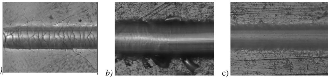
Figure 5-1: HVOF 80/20 Cr3C2-NiCr coating exhibiting cohesive failure after 1 year in service.
... 85 Figure 5-2: HVOF 80/20 Cr3C2-NiCr coating, sprayed with C3H6 after 1 year in the field. ... 90
Figure 5-3: HVOF 80/20 Cr3C2-NiCr coating, sprayed with C3H6 after 1 year in the field. ... 91
Figure 5-4: HVOF 80/20 Cr3C2-NiCr coating, sprayed with C3H6, after 30 thermal shocks going
from ambient temperatures to 675°C. ... 92 Figure 5-5: XRD spectrums of HVOF 80/20 Cr3C2-NiCr powder and coating, sprayed with C3H6.
Cr7C3 and Cr23C6 phases, even though not shown on the graph, could also be present. Peaks
overlapping has impeded their identification on all XRD spectrums presented in the paper. ... 93 Figure 5-6: Microstructure evolution during aging test at 704°C (1300ºF) after (a) 4 hour
exposure; (b) 120 hour exposure... 94 Figure 5-7: XRD spectrums of HVOF 80/20 Cr3C2-NiCr powder, “as sprayed” and aged
coatings, after 4 hour and 120 hour exposure to 704°C (1300ºF) respectively. ... 95 Figure 5-8: Coating #1 and #3 were repeatedly subjected to thermal shocks going from ambient temperatures to 675 °C. Then they were put through liquid penetrant tests to check for any
cracking. ... 99 Figure 5-9: XRD spectrums of HVOF material #1 and #2; powder and “as sprayed” coating. . 100 Figure 6-1: Schematic of sample configurations (a) 316 / W-WC, (b) 316 / Co-C / W-WC, (c) 718 / W-WC, and (d) 718 / Ni-W-Cr-B / W-WC. ... 106 Figure 6-2: Cross section views of the coating systems a) 316 / Co-Cr / WC, b) Co-Cr / W-WC high magnification, c) Co-Cr high magnification, and d) 718 / Ni-W-Cr-B / W-W-WC. ... 109 Figure 6-3: XRD spectra of the thin film and the two hardfacing materials. ... 110 Figure 6-4: a) EDS spectra of the thin film and the two hardfacing materials, b) line scan across a precipitated crystal in the Ni-W-Cr-B interlayer. ... 111 Figure 6-5: Adhesion using Rockwell C indentation according to CEN/TS/1071-8 standard for (a) 316 / W-WC, (b) 316 / Co-Cr / W-WC, (c) 718 / W-WC, and (d) 718 / Ni-W-Cr-B / W-WC coatings. ... 112 Figure 6-6: Cross section view of the microhardness measurements on 718 / Ni-Cr-B / W-WC. ... 113 Figure 6-7: Hardness with load for the different coating systems. ... 114 Figure 6-8: Wear rate (bars) and COF (dots) for each coating system. ... 115
Figure 6-9: Wear track profile for each coating system. ... 115
Figure 6-10: SEM images of wear tracks for (a) 316 / W-WC, (b) 316 / Co-Cr / W-WC, (c) 718 / W-WC, and (d) 718 / Ni-W-Cr-B / W-WC coatings. ... 116
Figure 6-11: OCP measurements for a) substrate and hardfacings, and b) the four coating systems. ... 118
Figure 6-12: EIS spectra for a) substrate and hardfacings, and b) the four coating systems. ... 119
Figure 6-13: Potentiodynamic polarization curves for a) substrate and hardfacings and b) the four coating systems. ... 120
Figure A-1: n-TiO2 powder characteristics: (a) SEM micrographs – A: anatase, R: rutile, (b) XRD pattern, and (c) particle size distribution – logarithmic scale ... 153
Figure A-2: Custom-designed automated variable temperature galling tester. ... 157
Figure A-3: Coating microstructures: Cr2O3 at (a) 150X and (b) 1000X. TiO2-Cr2O3 at (c) 150X and (d) 1000X. n-TiO2 at (e) 150X and (f) 1000X. n-TiO2-Cr2O3 at (g) 150X and (h) 1000X. 159 Figure A-4: EDS spectra of the Cr2O3, TiO2- Cr2O3, n-TiO2-Cr2O3 and n-TiO2-Cr2O3 materials. ... 160
Figure A-5: Coefficient of friction vs. sliding distance for the different coatings. ... 162
Figure A-6: Wear rate for the different coatings. ... 162
Figure A-7: Wear tracks after pin-on-disc tests at 50X. ... 163
Figure A-8: Wear tracks for specimens after dry abrasion testing. ... 164
Figure A-9: Wear tracks for specimens after wet abrasion testing. ... 164
Figure A-10: Galling resistance of self-mated specimens after variable temperature galling resistance. Mass loss is given between 0 (initial mass) and 100 cycles (i.e., after Step 2). ... 165
LIST OF ACRONYM AND SYMBOLS
Acronyms AISI ASTM APS BHN BRC BTO CEA CTE CVD DC DLC DPH DSI EDS EIS EOLVD EPA EPR EPRI ETC ETOAmerican Iron and Steel Institute
American Society for Testing and Material Air plasma spray
Brinnel hardness number Break torque to close Break torque to open
Comité à l’Énergie Atomique Coefficient thermal expansion Chemical vapor deposition Direct current
Diamond like carbon Diamond pyramid hardness Depth-sensing indentation Energy dispersive spectroscopy
Electrochemical impedance spectroscopy End of life vehicles directive
Environmental protection agency European pressurized reactor Electric Power Research Institute End torque to close
FCP FCSEL FEM HAZ HC HPAL HRC HRSG HRV HVOF IBAD ISO MIG MSBV NCP NRC NSERC OCP OEM PECVD POx PTA PTFE PVD PWR
Free corrosion potential
Functional Coating and Surface Engineering Laboratory Finite element modeling
Heat affected zone Hard chromium
High pressure acid leaching Rockwell hardness number Heat recovery steam generator Vickers hardness number High velocity oxy-fuel ion beam assisted deposition
International organization for standard Metal inert gas
Metal-seated ball valve
Nanostructured cobalt-phosphor National research council of canada
Natural sciences and engineering research council Open circuit potential
Original Equipment Manufacturers
Plasma enhanced chemical vapor deposition Pressure oxydation
Plasma transfer arc Polytetrafluoroethylene Physical vapor deposition Pressurized water reactor
ROHS RTC RTO S&F SCE SEM SMWA TIG TS UASC WWII XRD
Restriction of hazardous substances Run torque to close
Run torque to open Spray and fuse Standard electrode
Scanning electron microscope Shielded metal arc welding Tungsten inert gas
Thermal spray
Ultra advanced super critical World war II X-ray diffraction Symbols 3D Dg E Eb Ec Ecorr Er Es F H Three-dimensional Grain size Young modulus Breakdown potential
Young modulus of the coating Corrosion potential
Reduced young modulus Young modulus of the substrate Applied load
H/E H3/E3 HN HM HS Hv Ic Io k K K1c N S SCE V W
Elastic strain to failure Yield pressure Nano-hardness Micro-hardness Scratch hardness Vickers hardness Crystallinity index
Corrosion current density Hall-Petch material constant Wear Rate
Fracture toughness Normal load Sliding distance
Standard calomel electrode Worn volume Scratch width Greek Symbol Δm λ ε ρ σ σy Mass loss Wave Lenght Strain Density Stress Yield strength
υ μ
Poisson Ratio Shear modulus
LIST OF APPENDICES
APPENDIX A NANOSTRUCTURED AND CONVENTIONAL Cr2O3, TiO2 AND TiO2
-Cr2O3 THERMAL SPRAYED COATINGS FOR METAL-SEATED BALL VALVE
APPLICATIONS IN HYDROMETALLURGY ... 150 A.1. Introduction ... 150 A.2. Experimental ... 152 A.2.1. Materials ... 152 A.2.1.1. Base Material... 152 A.2.1.2. Powder Materials... 152 A.2.2. Deposition Techniques... 154 A.2.3. Characterization techniques ... 155 A.2.3.1. Microstructure ... 155 A.2.3.2. Mechanical Property Characterization ... 155 A.2.3.3. Tribological Behavior Assessment... 156 A.3. Results and discussion ... 158 A.3.1. Microstructure ... 158 A.3.2. Microhardness ... 160 A.3.3. Adhesion ... 161 A.3.4. Tribomechanical properties ... 161 A.3.5. Sliding Wear Resistance ... 161 A.3.5.1. Dry Sand Abrasion ... 163 A.3.5.2. Wet Sand Abrasion... 164 A.3.5.3. Variable Temperature Galling Resistance... 165 A.4. Conclusions ... 167 A.5. Acknowledgements ... 168
APPENDIX B TRIBOLOGY TERMS ... 170 B.1. Abrasion... 170 B.2. Adhesion ... 170 B.3. Coefficient of friction ... 170 B.4. Debris... 171 B.5. Erosion ... 171 B.6. Galling ... 171 B.7. Load-carrying capacity ... 171 B.8. Plastic deformation ... 171 B.9. Sliding wear ... 172 B.10. Spallation ... 172 B.11. Wear ... 172
INTRODUCTION
CHAPTER 1
Many industrial sectors, including transport, power generation, manufacturing, aerospace, and automobiles, are seeking new functional coatings, engineered surfaces, and interfaces in order to meet increasingly demanding performance requirements. Specifically, improvements are sought in the tribological properties (i.e., wear and corrosion resistance) as well as characteristics such as long-term stability in hostile environments.
According to the National Association of Corrosion Engineers, the cost of corrosion in the USA in 2006 was 430 billion US$, or 3.5% of the GDP. A more recent study by a private laboratory estimated the corrosion cost in the USA in 2013 at over $1 trillion, or 6.1% of the GDP [1]. Similar studies have shown that wear imposes 90 billion US$ in costs, or 0.75% of the GDP [2]. The seminal 1966 Jost Report, which generated a significant impact worldwide, estimated that up to 4% of the GDP could be saved in the UK by eliminating friction-related losses [3].
In this context, the valve industry is seeking new technologies that could provide high-quality coatings combining well-controlled tribological and corrosion performance with high mechanical integrity and environmental stability.
Figure 1: Ancient Roman in-line serviceable valve from Pompeii [4].
Pipes and valves are pressure vessels that regulate flow of materials, including liquids, gases, and slurries, by controlling the passageways. Pressure vessels have been used for thousands of years for various applications. Ancient depictions of piping systems show how they improved the quality of daily living. Based on remnants discovered by archeologists, we suspect that farming
villages were first established from 6,000 to 7,000 years ago during what historians refer to as the Neolithic Age.
It was during this time that the first successful systems to control water-irrigated agricultural fields were designed in Mesopotamia and Egypt, with the Sadd-el-Kafara dam in Egypt considered the world’s oldest large-scale dam [5]. Neolithic piping systems were intended mainly to prevent flooding, and were built of stone and terracotta. During the Bronze Age, Greeks and Romans developed sophisticated systems to supply water to urban centers around the Mediterranean, including dams, aqueducts, and reservoirs. They also developed an extensive canal transport system. Moreover, they initiated the design and manufacture of standard valves made of a copper alloy very similar to ASTM B67, illustrated in Figure 1.
Today, although valves are still used for water regulation and farming, the industrial revolution has considerably extended the scope of application. Valves are used to control steam machines and power plants that deliver electricity to cities and industries. Valves are also used to control the flow of natural resources such as oil, gas, and mining products during extraction, transportation, and processing, whereby these crude minerals are transformed into refined products.
Figure 2: Modern severe-service metal-seated ball valve.
To be competitive and to meet an enormous range of requirements, these processes are continuously optimized to target maximum production rates at lower cost and maintenance.
Seat
Optimizing processes typically involve the use of higher pressure and temperature and/or more aggressive chemicals that cannot be handled using off-the-shelf valves. These are usually referred to as severe-service conditions, which require tailored materials and valve designs. Whereas almost any valve type can be optimized for severe-service, metal-seated ball valves (MSBVs) are usually the preferred choice. As illustrated in Figure 2, the sphere of a MSBV is located within the valve body, where it opens and closes by rotating 90 degrees. In open position, the tunnel bore across the ball is aligned with the piping so that the flow is unobstructed, whereas in closed position the tunnel bore is perpendicular to the piping, blocking the flow. Two surfaces, called the sealing surfaces, provide the seal in closed position: one is the outside surface of the ball and the other is the spherical radius of the seats, which are located in the body and guide the ball. MSBV sealing surfaces are inherently protected from particles present in the flow in both open and closed position, ensuring a reliable shut-off. MSBVs are relatively easy to operate in a slurry application, because the ball rotates on itself without displacing solids present in the line while tolerating the use of very powerful drive systems. This ensures rapid closure in critical situations.
Figure 3: Typical damage to the sealing surfaces of a MSBV after service.
Severe-service MSBVs are therefore exposed to high pressure, high temperature, and/or highly corrosive environments. These grueling operating conditions are exacerbated by solids present in the flow that are wedged between the sealing surfaces. Sealing surface degradation is a major cause of severe-service valve failure, and can result in two different failure modes. The first occurs when the valve fails to cycle on demand due to excessive friction between the sealing
surfaces. The second occurs when the valve performs a cycle on demand but fails to seal in closed position due to imperfections in the sealing surfaces. Both failure modes can be caused by degradation of the sealing surfaces resulting from one of the wear mechanisms, including plastic deformation, abrasion, erosion, galling [6], and spallation combined with corrosion. As reported by several authors who performed failure analysis on severe-service MSBVs, and as illustrated in Figure 3, surface degradation is frequently caused by a combination of wear mechanisms that may or may not act in synergy [7-9]. Nevertheless, to prevent premature failure and mitigate wear, original equipment manufacturers (OEMs) use various types of surface treatments and invest heavily in R&D on surface engineering.
In response to the needs of valve manufactures, this research focuses on the development and characterization of a new generation of protective coating systems designed to extend valve life, whereby the microstructural features of films are controlled to achieve an optimal combination of surface and substrate properties that meet specific application requirements, with significant economic impact.
Background
After completing my Master’s degree in mechanical engineering in 2003, I arrived in Canada from France with a one-year visa and was soon hired as an R&D technician at the Velan Granby laboratory. My main duties were to help perform prototype tests on industrial valves exposed to pressures and temperatures ranging from cryogenic to 650 ºC. With my academic qualifications, I was pretty comfortable running R&D test set-ups, operating the old steam boiler, installing strain gauges, and using data acquisition systems. However, I was not prepared to properly inspect worn surfaces, draw conclusions, or select surface treatments.
Finding myself isolated in the countryside, I began to self-study wear, friction, and surface treatments. This interest was exacerbated by the Quebec climate with its unique challenges, namely the corrosion, temperature transients, and icing conditions (i.e., the extremely long and harsh winter). In 2005, after obtaining OIQ membership, I was placed in charge of the Velan Granby laboratory, where I developed a collaboration between Velan and the Functional Coating and Surface Engineering Laboratory (FCSEL) at Polytechnique Montréal. At first, we characterized worn surfaces and helped perform failure analyses on returned products. A year later, when Velan decided to merge the Granby laboratory with a new, larger entity located in Montreal, I moved back to the metropolis and returned to Polytechnique Montréal to follow evening classes on materials science and friction. In 2008, the three engineers who were developing the Velan severe-service MSBV line left the company almost simultaneously. Velan asked me to step in as manager of this line, which combines exotic materials with sophisticated surface treatments. The mandate was not only to oversee the engineering, but also to develop Velan’s coating know-how. I accepted both challenges and ended up with a considerable backlog, including boxes full of calculations, several products that had problems in the field, and no one to answer my questions.
It was at this time when I intensified Velan’s collaboration with FCSEL, working primarily with Professor Jolanta Ewa Klemberg-Sapieha to characterize worn surfaces, but also to assess and compare the tribological and mechanical behavior of various surface treatments used by Velan. The outcome of this relationship was the creation of a coating matrix designed to compare the
tribo-mechanical properties of different coatings applied to valves. Hardness (H), Young’s Modulus (E), and toughness were measured using microhardness indentation testers, and wear resistance under different conditions such as sliding wear and abrasion were measured by pin-on-disc and abrasion tests. In parallel, I helped prepare an application for a grant to enable us to acquire a novel high load tribometer to perform galling testing. This equipment is currently being purchased and will be used to complete our coating matrix.
With all those collaborations and my personal involvement as an external candidate, it was only natural that in 2009, when Professors Jolanta-Ewa Klemberg-Sapieha and Ludvik Martinu invited me to start a Ph.D. program within their group, I accepted their offer without hesitation. This was a way for me to not only strengthen the relationship between Velan and FCSEL, but more importantly, to develop new technologies.
Objectives
I have devoted the majority of my professional life to designing and manufacturing better valves. The objectives of this thesis are motivated by this long-term commitment, and by tangible opportunities that I believe are instrumental for advancing valve technology through a better understating of the fundamental physico-chemical mechanisms that govern surface degradation. Once the surface degradation mechanisms are fully understood (i.e., at the atomic level), a more suitable surface treatment can then be selected to inhibit specific wear mechanisms and ultimately extend valve life. Consequently, the fundamental chemical, metallurgical, mechanical, and physical concepts that govern surface degradation mechanisms must be accurately determined, and a variety of surface treatments can then be developed or improved.
The first objective arose from the fact that the U.S. Environmental Protection Agency (EPA) has classified hard chromium electroplating as an environmentally unfriendly process. In accordance with Porter’s hypothesis that environmental regulations should trigger the discovery and introduction of not only cleaner but also more efficient technologies, thereby improving a company’s commercial competitiveness, nanostructured coatings appeared to be viable alternatives from both an engineering and a commercial perspective. Therefore, the objective of the study was to select the best
candidates for alternatives to hard chromium electroplating. To do so, several factors were considered, including the mechanical and tribological performance of recently developed coating technologies, potential supply chains, and long-term economic viability. In order to further mitigate the risks associated with the use of alternative treatments, the wear mechanism of hard chromium plating slid against Stellite 6 was examined to comprehend the tribological behavior behind the superior galling resistance of this material couple, and to compare it with the mechanisms for potential alternative coating materials when slid against Stellite 6. The ultimate goal was to select surface treatments that provide the equivalent mechanism to that for hard chromium.
The second objective was to determine the cause of the recurrent failures occurring in the field with thermal sprayed HVOF Cr3C2-NiCr coating applied to Inconel 718 PH when
exposed to supercritical steam lines and thermal shocks in modern power plants. HVOF 80/20 Cr3C2-NiCr coating has been used to protect thousands of MSBVs over the years,
without incident. However, modern power plants expose valves to the added challenge of rapid high pressure and temperature variations, resulting in a severe-service situation where coatings undergo cracking and cohesive failure. The purpose of this study was therefore to fully understand the degradation mechanism causing the coating failures and to evaluate potential coating alternatives to reduce the effects and improve the reliability.
The third objective was to study the effects of the mechanical properties of a material carrying a thin surface treatment on the tribo-mechanical and corrosion performance of the coating system. This objective was driven by thin film failures reported by end-users, attributed to high stresses at the interface and within the substrate material when subjected to highly concentrated load, leading to high stress levels that eventually cause permanent surface indentation, crack formation, and/or spallation. These failure modes are called brinelling (indentation due to substrate plastic deformation) and eggshell-effect (coating fracture and/or coating spallation). The purpose of this study was to design and produce innovative graded coating systems consisting of 1) a thin surface treatment with high hardness (H) and excellent sliding wear properties, and with superior mechanical behavior to that of conventional base materials used in the valve industry; and 2) a
hardfaced interlayer with a strain-to-failure characteristic between that of the substrate and surface material in order to reduce the mechanical properties gradient and therefore reduce the risk of premature failure due to inadequate load carrying capacity.
Thesis outline
This thesis is divided into seven chapters, beginning with the introduction.
Chapter 2 presents a literature review of the key elements required to fully understand this project. Chapter 3 presents the methods used for coating characterization. The three articles resulting from this work report the main results, and are presented in chapters 4 to 6.
Specifically, Chapter 4 presents a comparative analysis of two nanostructured coatings as alternatives to hard chromium: electrodeposited nanostructured cobalt-phosphor and chemical-vapor-deposited tungsten/tungsten carbide. The wear mechanisms that occur when hard chromium plating is slid against Stellite 6 under high load were investigated. After examining these interactions at the crystal structure level and determining those that are responsible for the exceptional tribological behavior of this material couple, the authors recommended an alternative material to hard chromium that provides a similar wear mechanism when slid against Stellite 6. Chapter 5 presents a case study stemming from an investigation of a thermal sprayed HVOF Cr3C2-NiCr coating failure for an on-off metal-seated ball valve (MSBV) used in supercritical
steam lines in a power plant. HVOF 80/20 Cr3C2-NiCr coating has been used to protect
thousands of MSBVs, without incident. However, in this case the valves were exposed to the additional challenge of rapid high pressure and temperature variations, resulting in a severe-service situation where the coating underwent cracking and cohesive failure. After an in-depth failure analysis, the authors determined the mechanism that led to the failure and subsequently evaluated potential coating alternatives.
Chapter 6 examines the combination of hardfaced superalloy and thin film to produce superior mechanical performance to that of each individual layer. A critical issue in the deposition of hard
coatings onto softer substrates is the mismatch between thermal expansion and the elasto-plastic and structural characteristics. This causes high compressive mechanical stress, and hence weak adhesion [10]. There is increasing evidence that the optimum solution to erosive, corrosive, and adhesive wear problems lies in the design and manufacture of multilayered, graded, and/or nanostructured coatings and coating systems that combine controlled hardness and elastic modulus, high toughness, and good adhesion [11]. The aim of this study was to characterize two coating systems composed of 1) a hard thin film top layer, which provides superior tribological properties, and 2) a hardfaced interlayer, which increases the surface load-carrying capacity by reducing the elasto-plastic gradient and peak stresses. The first coating system consists of a tungsten–tungsten carbide thin film (W-WC) deposited by chemical vapor deposition onto a laser cladded Co-Cr hardfaced interlayer (Stellite® 6) applied to a 316 stainless steel substrate, and the second consists of the same W-WC top layer and a high velocity oxygen fuel sprayed and fused Ni-W-Cr-B hardfaced interlayer (Colmonoy® 88) applied to an Inconel® 718 substrate.
Chapter 8 summarizes the contributions of this thesis and recommends avenues for future research.
Appendix A presents a detailed characterization project in which promising ceramic coatings were assessed for mechanical and tribological resistance. The goal was to better understand and harness the performance of the most promising ceramic coatings for hydrometallurgy processes, including pressure oxidation (POx) and high-pressure acid leaching (HPAL). Included was a novel n-TiO2-Cr2O3 blend as a candidate for hydrometallurgy application, where air plasma
sprayed ceramic coatings are vital to protect machines in the harsh abrasive conditions of corrosive POx and HPAL processes. Hardness, Young’s modulus, adhesion, shear strength, and toughness were assessed using microhardness indentation testers and universal tensile testing equipment. Wear resistance of the coatings under various conditions such as sliding wear and abrasion were measured by standard pin-on-disc and abrasion tests.
My research work as presented in this thesis has resulted in numerous publications, as follows: Table 1: Peer-reviewed publications
L.Vernhes, M. Azzi, E. Bousser and J.E. Klemberg-Sapieha, “Hybrid Co-Cr / W-WC and
Ni-W-Cr-B / W-WC Coating Systems Hardfacing Superalloy as Interlayer for Thin Film”, submitted to Journal of Thermal Spray Technology, 2014.
L.Vernhes, D.A. Lee, D. Poirier, D. Li and J.E. Klemberg-Sapieha, “HVOF Coating Case Study
for Power Plant Process Control Ball Valve Application”. Journal of Thermal Spray Technology, 2013.
L. Vernhes, M. Azzi and J.E. Klemberg-Sapieha, “Alternatives for hard chromium plating:
Nanostructured coatings for severe-service valves”. Materials Chemistry and Physics, 2013.
Table 2: Peer-reviewed publications written in collaboration
M. Azzi, L.Vernhes, E. Bousser and J.E. Klemberg-Sapieha, “Mechanical, Tribological and Corrosion Properties of Co-Cr and NiWCrB Hardfacing Superalloy Coating Systems”. ASME 2014 International Mechanical Engineering Congress and Exposition, 2014.
Table 3: Working paper
L.Vernhes, C. Bekins, N. Lourdel, D. Poirier, R.S. Lima, D. Li and J.E. Klemberg-Sapieha,
“Nanostructured and Conventional Cr2O3, TiO2 And TiO2-Cr2O3 Thermal Sprayed Coatings for
Metal-seated Ball Valve Applications in Hydrometallurgy”.
Table 4: Conference proceedings and poster presentations
L.Vernhes, C. Bekins, N. Lourdel, D. Poirier, R.S. Lima, D. Li and J.E. Klemberg-Sapieha,
“Nanostructured and Conventional Cr2O3, TiO2 and TiO2-Cr2O3 Thermal Sprayed Coatings for
Metal-seated Ball Valve Applications in Hydrometallurgy”. International Thermal Spray Conference, Barcelona, Spain, 2014.
L.Vernhes, C. Bekins, N. Lourdel, D. Poirier, R.S. Lima, D. Li and J.E. Klemberg-Sapieha,
“Nanostructured and Conventional Cr2O3, TiO2 and TiO2-Cr2O3 Thermal Sprayed Coatings for
Metal-seated Ball Valve Applications in Hydrometallurgy”. Alta, Perth, Australia, 2013.
L.Vernhes, D.A. Lee, D. Poirier, D. Li and J.E. Klemberg-Sapieha, “HVOF Coating Case Study
for Power Plant Process Control Ball Valve Application”. Reliability, Durability and Performance Assessment of Thermal Spray Coatings Conference, Albany, New York, USA, 2013.
L.Vernhes, D.A. Lee, D. Poirier, D. Li and J.E. Klemberg-Sapieha, “HVOF Coating Case Study
for Power Plant Process Control Ball Valve Application”. Valve World, Dusseldorf, Germany, 2012.
L.Vernhes, D.A. Lee, D. Poirier, D. Li and J.E. Klemberg-Sapieha, “HVOF Coating Case Study
for Power Plant Process Control Ball Valve Application”. International Thermal Spray Conference, Houston, USA, 2011.
L.Vernhes, D.A. Lee, D. Poirier, D. Li and J.E. Klemberg-Sapieha, “HVOF Coating Case Study
for Power Plant Process Control Ball Valve Application”.Saudi Aramco Global Reliability and Safety conference, Houston, USA, 2011.
L. Vernhes, M. Azzi and J.E. Klemberg-Sapieha, “Alternatives for hard chromium plating:
Nanostructured coatings for severe-service valves”. Society of Vacuum Coaters Conference, poster, FCSE, Montréal, QC Canada, 2011
L. Vernhes, M. Azzi and J.E. Klemberg-Sapieha, “Alternatives for hard chromium plating:
Nanostructured coatings for severe-service valves”. Society of Vacuum Coaters Conference, Albuquerque, USA, 2010.
Table 5: Patents
Seat arrangement with cavity pressure relief for a ball valve, US Patent No. 8,002,237, 2010. A ball valve resilient seat arrangement is provided that permits relief of cavity pressure. When the cavity pressure reaches a certain level, a sealing point between the seat and the valve body is lost. Communication is thereby provided between the space and the valve passage to achieve cavity pressure relief.
Spring energized resilient Seat for a ball valve, US Patent No. 8,500,090, 2013.
A ball valve resilient sealing ring is provided for sealing between a ball valve member and a valve body. The sealing ring may comprise a ring body having a ball valve member- contacting surface and one or more valve body-contacting shoulders for contacting the valve seat. The resilient sealing ring may comprise an elastic ring core for providing bending resistance.
Table 6: Memberships
Ordre des Ingénieurs du Québec
American Society for Testing and Materials, Committee officer, Subcommittee G02
International Organization for Standardization, P-member, Subcommittee SMC/ISO/TC153/SC1 American Society of Materials
LITERATURE REVIEW
CHAPTER 2
The literature review is divided into three sections to address the three components of this doctoral thesis. The first section provides a historical and state-of-the-art review on materials and surface engineering methods used in the valve industry, along with their limitations; the second summarizes surface engineering methods used to improve tribological behavior; and the third reviews the relationships between material properties and tribological behavior. A glossary of tribological terms is provided in the Appendix, including wear mechanisms and the underlying tribological processes.
2.1. Surface engineering methods applied to valves
2.1.1. Historical development
As mentioned in the introduction, valves were invented thousands of years ago to supply water to farms and cities. These antique valves were made of bronze alloys. Bulk bronze provides good corrosion resistance and acceptable tribological performance, and bronze continues to be used today for similar applications. The first significant technological challenge that triggered the introduction of new materials for valves occurred in 1705, when Thomas Newcomen invented the first steam engine able to convert steam power into mechanical work using the Rankine thermodynamic cycle. Although valves that were originally designed for water piping systems were first used for steam engines, the advent of the railroad facilitated access to cast iron, and valve manufacturers adopted this strong material to manufacture steam valves [12]. The first patent for a valve in the U.S. was filed by James Robertson in 1840. At that time, some of the legendary valve companies were founded, including Crane and Powell, which are still in operation today. In the 1860s, the Chapman Valve Manufacturing Company patented the now classical wedge gate valve.
Steam engine designs were optimized over the years, gradually replacing horses to power industrial equipment such as water pumps and locomotives. Efforts to improve the efficiency of the Rankine cycle by raising steam temperature and pressure began during the industrial revolution (approximately 1760–1840). In the 19th century, iron valves with bronze sliding surfaces were introduced. Higher-strength cast irons were also developed toward the end of the
19th century to support increasing temperature and pressure requirements at power plants where steam-powered turbines drove electrical generators. Engineering firms such as Boulton & Watt, founded by Matthew Boulton and James Watt in the UK in 1775, were pressing valve manufacturers to develop new valve materials capable of regulating steam flows at temperatures up to 260 °C and pressures up to 13.7 bars. Up to the beginning of the 20th century, valve sliding surfaces were made of bronze, and the first major innovation in materials was the invention of a copper–nickel alloy by David H. Brownein in 1906. It was commercialized under the trade name Monel. Solid Monel provided greater hardness combined with better corrosion and wear resistance compared to bronze. It therefore replaced bronze for the protection of critical sliding areas of valves, thereby extending their in-service life [13].
The next new material to be adopted by the valve industry was martensitic stainless steel, patented in 1912 by Elwood Haynes, who discovered it while developing corrosion-resistant materials for horseless carriages. With its typical body-centered tetragonal microstructure obtained by heat treatment, martensitic stainless steel provides higher strength than Monel and good tribological performance. In addition, the 13% chrome content ensures satisfactory corrosion resistance, which made it the material of choice at that time for critical valve sliding areas [14]. Elwood Haynes subsequently patented a cobalt alloy commercialized under the trade name Stellite in 1913. Composed of chrome carbides embedded in a cobalt-based matrix, this alloy exhibits a low friction coefficient under highly loaded sliding contact, and it has become
the standard wear-resistant material in the valve industry [15].
A low coefficient of friction, superior corrosion resistance, and high resistance to adhesion between the contact surfaces under high sliding load (called galling) are the three primary wear attributes of Stellite. These features prevent equipment seizure, surface deterioration, and gross material transfer between two counter bodies [16]. As reported by several authors, Stellite alloys exhibit a particular wear mechanism under high-load sliding wear: material transfer is restricted to a nanoscale thin superficial layer that is easily sheared, and which acts as a solid lubricant while preventing catastrophic galling and seizure [17]. This thin layer results from a phase transformation under high load: from face-centered cubic (fcc) to hexagonal close-packed (hcp), providing a preferred slip on the basal plane oriented parallel to the sliding interface. The
preferred slip plane provided by the low COF of hcp structures was theoretically demonstrated by Buckley and Johnson (1968), and the resulting lamellar structures are useful features of common solid lubricant materials such as graphite, molybdenum disulfide, and boron nitride [18]. Figure 2-1 shows Stellite under highly loaded sliding contact, revealing a thick fcc interlayer and an easily sheared hcp top layer that is regenerated when worn.
Figure 2-1: Wear mechanism of Stellite under highly loaded sliding contact: a) the typical dendrite structure is visible in the bulk material along with the heavily deformed top layer; b) the thin top layer is transformed under high load from fcc phase to hcp phase; c) fragmented carbides are visible in the top layer; and d) transmission electron microscopy of the top layer, showing the thin top layer composed of hcp phase oriented parallel to the sliding interface [19].
This easily sheared superficial layer eases the transfer to a non-stellite counter material, and therefore Stellite against Stellite sliding contact occurs, even when only one of the two counter bodies is originally constituted of Stellite, as discussed in Chapter 4 [19].
The invention of this adaptive material marked the beginning of a century of Stellite’s quasi-monopoly in the valve industry, with grade 6 being the most widely used, disturbed only by the introduction of a novel non-metallic material called Teflon, which Dupont patented in 1938. During World War II, the US army, needing a fast-acting tight shutoff compact valve with better corrosion resistance than martensitic steel, developed the resilient-seated austenitic stainless steel ball valve. Based on the ball valve design patented in 1871 by John Warren and John Chapman, which required bronze sliding surfaces, the first mass-produced ball valves were built with the
a) b)
now ubiquitous fluoropolymer material. These innovative ball valves played an instrumental role in high octane gasoline refining and the production of other valuable oil-based products required to support the war effort [20].
After the war, resilient-seated austenitic stainless steel ball valves were first commercialized by the Jamesbury Corporation, founded by Howard G. Freeman. They are still used extensively for corrosive chemical and petrochemical processes, where they have been made more abrasion-resistant, and where the range of application has been extended beyond the PTFE temperature limit [21]. Thus, valve manufacturers have developed austenitic stainless steel ball valves equipped with Stellite seat rings and hard chrome plated austenitic stainless steel balls that can operate at 700 ºC while providing excellent corrosion resistance. New nickel-based superalloys such as Alloy 20, Hastelloy X (also developed by Haynes, the trade name being a combination of Haynes and Stellite), Monel K-500, Inconel 625, Nimonic, and Waspalloy were developed during the boom decades after the Second World War, extending both the operating temperature and corrosion resistance of valves and piping [22]. Electroless nickel plating combined with heat treatment was also introduced for application to austenitic stainless steel balls coated with hard chrome that were exposed to attack by weak acids solutions (e.g. nitric or hydrochloric acid). Occasionally, electroless nickel was applied between the austenitic stainless steel and hard chrome layers as a corrosion barrier to mitigate corrosion attack while retaining the superior wear resistance of hard chrome [22].
In parallel with the arrival of new chemicals, petrochemicals, and corrosion-resistant alloys, newly engineered chromium-rich steels helped raise the operating temperatures of steel valves, enabling engineering firms to improve power plant efficiency by operating above the vapor– liquid critical point. In the 1960s, the first supercritical power plant operating with steam at 600 °C and 290 bar was launched in Ohio, US [23]. Since the close of the 20th century, the severe-service metal-seated valve industry has moved away from traditional, relatively soft anti-galling Stellite to embrace hard thermal sprayed coating materials for the most demanding applications. The two main drivers for this change were 1) the severe corrosiveness of modern chemical processes, which require application-specific surface treatments, and 2) the need for more
wear-resistant surface treatments that resist erosion and abrasion caused by particles present in the flow while providing a longer life cycle [24].
2.1.2. State-of-the-art materials and challenges
Stellite, hard chrome plating, and Teflon remain the dominant wear-resistant materials in the valve industry. However, continuous advances in industrial processes have called for the development of new corrosion- and wear-resistant surface treatments that, despite their enhanced performance, have difficulty meeting ever-evolving industry needs. Optimized tribological solutions developed over the last decade have already reached their limit for certain extreme applications, and the evidence shows that a substantial number of surface treatment challenges remain to be overcome.
This chapter describes some of the new materials used in the valve industry over the past two decades as well as the most pressing challenges that remain, including those addressed in this doctoral research project.
2.1.2.1. Fossil power generation
In the last 20 years, combustible costs, environmental policies, and a growing demand for electric power have motivated engineering companies such as GE and Siemens to improve the efficiency of power plants [25]. Accordingly, coal-fired power generation technologies have evolved to operate with steam at higher temperatures and pressures in order to increase efficiency, as explained by the thermodynamic laws [12]. Today, most modern power plants operate at above the vapor–liquid critical point, producing more power output at higher thermal efficiency. These state-of-the-art power plants, called supercritical (SC) combined cycle power plants, work at 600 ºC, use 9% chromium steel alloy valves with superior high temperature properties, and are equipped with heat recovery steam generators (HRSG) that recover waste heat from hot exhaust gas in order to power auxiliary turbines, hence converting over 45% of the fuel energy into electricity [26].
In addition to operating under extreme steam temperatures and pressures, the power plants are run during peak usage times. Consequently, SC power plants cycle several times per day in order
![Figure 2-3: Typical burnishing effects with varying force using a 22 mm roller on steel of 220 HV hardness (0.20% C; 0.30% Si; 0.80% Mg; 0.05% P; 0.05% S) [89]](https://thumb-eu.123doks.com/thumbv2/123doknet/2351182.36309/56.918.259.666.112.417/figure-typical-burnishing-effects-varying-roller-steel-hardness.webp)
![Figure 2-4: Hardness as a function of temperature obtained by diffusion coatings made with different compounds [70]](https://thumb-eu.123doks.com/thumbv2/123doknet/2351182.36309/58.918.311.607.112.529/hardness-function-temperature-obtained-diffusion-coatings-different-compounds.webp)
![Figure 2-10: Cross section of a basic flame spray gun [104].](https://thumb-eu.123doks.com/thumbv2/123doknet/2351182.36309/65.918.243.673.673.911/figure-cross-section-basic-flame-spray-gun.webp)
![Figure 2-16: Wear rate of several TS coatings compared to HC coatings during the Taber Abraser test – ASTM F1978 [117]](https://thumb-eu.123doks.com/thumbv2/123doknet/2351182.36309/71.918.209.708.107.426/figure-wear-coatings-compared-coatings-taber-abraser-astm.webp)
![Figure 2-20: nanocrystalline-TiN/aSiN nanocomposite formation and mechanical properties [128]](https://thumb-eu.123doks.com/thumbv2/123doknet/2351182.36309/74.918.152.763.783.1000/figure-nanocrystalline-tin-asin-nanocomposite-formation-mechanical-properties.webp)


![Table 5.1: Comparison of failed versus new HVOF 80/20 Cr 3 C 2 + [80Ni-20Cr] coating and OEM](https://thumb-eu.123doks.com/thumbv2/123doknet/2351182.36309/116.918.203.715.631.902/table-comparison-failed-versus-new-hvof-coating-oem.webp)
