© Zhao Chen, 2019
Multiscale Characterization and Modeling of the
Viscoelasticity of the Cement Paste and the Alike
Calcium-Silicate-Hydrate (C-S-H) at Different Levels of
Relative Humidity
Thèse
Zhao Chen
Doctorat en génie civil
Philosophiæ doctor (Ph. D.)
Multiscale characterization and modeling of the
viscoelasticity of the cement paste and the alike
calcium-silicate-hydrates (C-S-H) at different levels
of relative humidity
Thèse de doctorat
Zhao Chen
Sous la direction de :
Luca Sorelli, directeur de recherche
Julien Sanahuja, codirecteur de recherche
ii
Résumé
Le phénomène de fluage, qui est défini comme la déformation dessous une charge constante, a un effet à long terme sur la déformation des structures en béton armé. Récentes recherches montrent que la déformabilité de structures en béton armé du au fluage après quelques décades est largement sous-estimée par les normes. Plusieurs recherchent montrent que le fluage à long terme du béton suit une loi logarithmique dans le temps. Le fluage du béton provient de la microstructure du silicate de calcium (C-S-H) hydratée. Bien que de nombreux travaux expérimentaux et théoriques aient été réalisés, les mécanismes de fluage du C-S-H demeurent mal connus. Parmi les facteurs qui influent sur le comportement au fluage du C-S-H, l’humidité relative (HR) est le principal. En fait, la teneur en eau dans les microspores joue un rôle important dans la rigidité, la résistance et la viscosité de la microstructure C-S-H. La technique d'indentation permet de caractériser les propriétés mécaniques de la pâte de ciment à l'échelle microscopique et nanométrique à laquelle les mécanismes de fluage agissent. Par rapport aux expériences de fluage traditionnelles qui durent des mois et des années, le test d'indentation présente l'avantage d'évaluer les propriétés de fluage des matériaux à base de ciment en quelques minutes. De plus, il est plus facile pour l’échantillon d’atteindre l’équilibre humidité en raison du petit volume sondé. Pour extraire correctement les propriétés de fluage, la première étape consiste à établir une méthode d’essai d'indentation viscoélastique. Pour cette étude, la microindentation viscoélastique est analysée respectivement par une pointe sphérique et une pointe de Berkovich. Les propriétés de fluage à long terme sont bien décrites par le paramètre module de fluage de contact (C) de la complaisance au fluage logarithmique. Les propriétés mécaniques de structures C-S-H semblables à celles de Jennite et de Tobermorite à 1.4 nm sont ensuite caractérisées par une microindentation à différents niveaux d’HR. À différents niveaux d’HR, le comportement de fluage et de relaxation des C-S-H est étudié par la nanoindentation statistique sur une pâte de ciment. Le rôle de l'eau sur le comportement au fluage de C-S-H est réexaminé. De nouvelles découvertes concernant le mécanisme de fluage de C-S-H sont présentées et discutées.
iii
Abstract
The phenomenon of creep has a long-term effect on the durability of the concrete structures. It has been widely agreed that concrete creep originates from the microstructure of calcium-silicate-hydrates (C-S-H). Being a formidable problem, the creep mechanism of C-S-H is still an enigma although numerous experimental and theoretical works have been done. Among the factors affecting the creep behavior of C-S-H, relative humidity (RH) is the primary one. The water content in the micropores plays an important role in the stiffness, the strength, and the viscosity of the microstructure C-S-H. The indentation technique allows characterizing the mechanical properties of the cement paste at the microscale and the nanoscale. Notably, the phenomenon of creep can be observed during the indentation holding phase. Compared with the traditional creep experiments lasting for months and years, indentation testing has the advantage of assessing the creep properties of the cement-based materials in minutes. In addition, it is easier for the specimen to reach the moisture equilibrium because of the small volume probed. To properly extract the creep properties, the first step is to establish the scheme of viscoelastic indentation. For this study, viscoelastic microindentation is analyzed by a spherical and a Berkovich indenter tip, respectively. The long term creep properties are well captured by the parameter of contact creep modulus (C) from logarithmic creep compliance. The mechanical properties of alike C-S-H structures of jennite and 1.4 nm tobermorite are then characterized by microindentation at various levels of RH. At the two levels of RH, the creep and the relaxation behavior of C-S-H is finally investigated by the statistical nanoindentation on a cement paste. The role of the water on the creep behavior of C-S-H is re-examined. The new findings for the creep mechanism of C-S-H are presented and discussed.
iv
Contents
Résumé ... ii
Abstract ... iii
Contents ... iv
List of figures ... vii
List of tables ... x Nomenclature... xi Acknowledgment ... xiii Foreword ... xiv Introduction ... 1 Industrial problem ... 1 Research problem ... 2 Objectives ... 4 Originality ... 5 1. Literature survey ... 6
1.1 Hardened cement paste ... 6
1.2 Calcium silicate hydrates (C-S-H) ... 8
1.3 Alike C-S-H structures ... 11
1.4 Effect of relative humidity on concrete creep ... 14
1.5 Creep mechanisms ... 18
1.6 Background of indentation ... 22
1.6.1 Basis of indentation ... 22
1.6.2 Viscoelastic indentation ... 24
1.6.3 Plastic effect ... 25
1.6.4 A logarithmic creep model ... 26
1.6.5 Nanoindentation and microindentation testing ... 27
1.6.6 Statistical nanoindentation ... 28
2. Article 1: A double-mechanism viscoelastic model to analyze the creep response of a cement paste by microindentation ... 30
Résumé ... 30
Abstract ... 31
2.1 Introduction ... 32
2.2 Materials and methods ... 34
2.2.1 Materials preparation ... 34
2.2.2 Microindentation tests ... 35
2.2.3 Basics of microindentation ... 36
2.2.4 Viscoelastic indentation ... 37
2.2.5 Simplified creep model ... 40
2.3 Results ... 44
2.3.1 Experimental ... 44
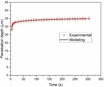
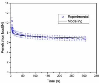
2.3.2 Modeling creep and relaxation microindentation tests ... 47
2.4 Discussion ... 50
v
2.4.2 Correlation between the spherical microindentation creep compliance and
relaxation modulus ... 51
2.4.3 Viscoelastic modeling of the loading phase of spherical microindentation creep and relaxation ... 52
2.5 Conclusions ... 54
3. Article 2: Duality between creep and relaxation of a cement paste at different levels of relative humidity: characterization by microindentation and analytical modeling ... 56
Résumé ... 56
Abstract ... 57
3.1 Introduction ... 58
3.2 Materials and methods ... 60
3.2.1 Materials ... 60 3.2.2 Humidity chamber ... 61 3.2.3 Surface roughness ... 62 3.2.4 Basics of microindentation ... 62 3.2.5 Microindentation tests ... 64 3.2.6 Viscoelastic analysis ... 65 3.2.7 Plastic effect ... 68
3.2.8 Logarithmic creep compliance ... 70
3.2.9 Power-law creep compliance ... 71
3.3 Results and discussion ... 72
3.3.1 Viscoelastic modeling ... 74
3.3.2 Viscoelastoplastic modeling ... 76
3.3.3 Modeling long-term creep and relaxation rates ... 79
3.4 Conclusion and outlook ... 81
4. Article 3: Creep microindentation of tobermorite and jennite: effect of relative humidity and porosity ... 83
Résumé ... 83
Abstract ... 84
4.1 Introduction ... 85
4.2 Materials and methods ... 87
4.2.1 Material preparation ... 87
4.2.2 Mercury intrusion porosimetry (MIP) ... 87
4.2.3 Relative humidity chamber ... 88
4.2.4 Experimental procedure ... 88 4.2.5 Methods ... 89 4.3 Results ... 90 4.3.1 MIP porosity ... 90 4.3.2 Microindentation ... 90 4.3.3 Creep properties ... 93 4.4 Simplified analysis ... 98 4.5 Concluding remarks ... 101
5. Article 4: The effect of water content on the creep and relaxation behavior of calcium silicate hydrate (C-S-H) phase of a cement paste microstructure by statistical nanoindentation ... 103
vi
Abstract ... 104
5.1 Introduction ... 105
5.2 Materials and methods ... 107
5.2.1 Materials preparation ... 107
5.2.2 Polishing protocol ... 108
5.2.3 Humidity chamber ... 108
5.2.4 Background of nanoindentation ... 109
5.2.4.1 Load control and depth control ... 110
5.2.4.2 Testing parameters ... 111
5.2.4.3 Analysis of the nanoindentation creep and relaxation ... 112
5.2.4.4 Statistical nanoindentation ... 114
5.3 Results ... 115
5.3.1 Cluster deconvolution by statistical nanoindentation ... 115
5.3.1.1 Cluster 1 ... 116
5.3.1.2 Cluster 2 ... 117
5.3.1.3 Cluster 3 ... 118
5.3.1.4 Cluster 4 ... 119
5.3.2 Nanoindentation creep and relaxation curves of CSH phase ... 122
5.4 Analysis and discussion ... 124
5.4.1 Modeling nanoindentation creep and relaxation of C-S-H ... 124
5.4.2 Short-term creep mechanism of C-S-H with different water content ... 129
5.5 Conclusions ... 131
Discussion, conclusions, and future outlook ... 133
Discussion ... 133 Conclusions ... 136 Contributions ... 140 Future outlooks ... 140 Appendix A ... 142 Appendix B ... 143 References ... 145
vii
List of figures
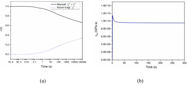
Figure 1-1. A multiscale view of concrete materials adapted from [24,32,33]. ... 6 Figure 1-2. Microstructure of (a) flocculated C-S-H, (b) platy crystals of CH, and needle-like ettringite by scanning electron microscope (SEM) [37]. ... 8 Figure 1-3. (a) Schematic illustration of C-S-H nano-particles [38]; (b) the molecular model of a C-S-H nano-particle [30]. ... 9 Figure 1-4. A schematic diagram of (a) LD C-S-H and (b) HD C-S-H composed of spherical C-S-H nano-particles adapted from [40]. ... 10 Figure 1-5. Various formations of C-S-H [49]. ... 12 Figure 1-6. Crystal structures of (a) jennite and (b) tobermorite [44,55]. ... 13 Figure 1-7. SEM secondary electron image of (a) platy crystals of Al-tobermorite and (b) C-A-S-H and Al-tobermorite [47,58]. ... 14 Figure 1-8. (a) An example of uniaxial concrete creep [23]; (b) Shifted basic and drying concrete creep. ... 15 Figure 1-9. (a) Mean microindentation creep and (b) relaxation curves of cement paste (w/c=0.6) at various levels of RH [10]. ... 18 Figure 1-10. A model for the microstructure of C-S-H adapted from [25,86]. ... 19 Figure 1-11. Water diffusion of hindered adsorption in the smaller gel pores to the larger gel pores or capillary pores under the pressure, (a) initial state and (b) applied pressure, adapted from [88]. ... 20 Figure 1-12. A schematic diagram of rearrangement of C-S-H particles (a) without and (b) with stress disturbance adapted from [31]. ... 21 Figure 1-13. (a) Schematic illustration of indentation testing and (b) A typical curve of penetration load (P) versus penetration depth (h). ... 24 Figure 1-14. A schematic illustration of nanoindentation and microindentation on the specimen of cement paste. ... 27 Figure 2-1. A schematic diagram of spherical indentation. ... 36 Figure 2-2. (a) Microindentation creep test and (b) microindentation relaxation test. ... 36 Figure 2-3. Load-depth curves of (a) microindentation creep test and (b) microindentation relaxation test. ... 37 Figure 2-4. A schematic illustration of the creep model adapted from [127]. ... 41 Figure 2-5. The residual indentation of the 10X10 matrix microindentation creep test. ... 45 Figure 2-6. (a) Mapping for creep tests of (a) indentation modulus (M); (b) indentation hardness (H). Mapping for relaxation tests of (c) indentation modulus (M); (d) indentation hardness (H). ... 46 Figure 2-7. (a) Experimental penetration depth of creep tests; (b) experimental penetration load of relaxation tests. ... 46 Figure 2-8. Comparison of experimental and modeling response in terms of penetration depth versus time for creep microindentation tests. ... 47 Figure 2-9. Validation of modeling the relaxation load P(t) with the parameters extracted from the creep modeling. ... 48 Figure 2-10. (a) Dimensionless creep strain; (b) Maxwell viscosity in the function of time for creep microindentation. ... 49
viii
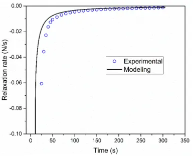
Figure 2-11. As for relaxation tests: (a) Dimensionless relaxation stress; (b) Maxwell viscosity in function of time for relaxation microindentation. ... 49 Figure 2-12. Modeling the Berkovich microindentation creep (a) and relaxation (b). ... 50 Figure 2-13. Experimental and modeling of relaxation rate of Berkovich microindentation. ... 51 Figure 2-14. Comparison of relaxation modulus ( )E t and creep complianceJ t( )1. ... 52
Figure 2-15. Comparison of relaxation modulus ( )E t and creep complianceJ t( )1
. ... 52 Figure 2-16. Modeling the loading phase of spherical microindetation creep and relaxation tests. ... 54 Figure 3-1. Two MIP measurements of the pore size distribution of the studied cement paste. ... 60 Figure 3-2. (a) Hermetic chamber with humidity sensor and the CO2 sensor connected in
series to an air pump and an Erlenmeyer flask containing the solution of saturated salt; (b) AFM surface image of cement paste surface on an area of 50 m 50 m [10]. ... 62 Figure 3-3. (a) Schematic view of an indentation test with a conical indenter; (b) Load versus penetration depth response; (c) Load and displacement versus time. ... 64 Figure 3-4. View of the indentation imprints at different magnification by digital microscope (the length scale of 100 m). ... 65 Figure 3-5. (a) Example of indentation grid on the cement paste for RH=33%; (b) mapping of the indentation hardness (GPa); (c) mapping of the indentation modulus (GPa) [10]. .... 73 Figure 3-6. (a) Creep tests: penetration depth versus time during the holding phase; (b) Relaxation tests: applied load versus time during the holding phase. ... 73 Figure 3-7. Viscoelastic analysis: Comparison between the experimental and simulated results for the (a) creep tests; (b) relaxation tests. ... 75 Figure 3-8. (a) Comparison in term of creep compliance parameters (Ev1 and 1 or Ev2 and 2)
versus RH for the viscoelastic and viscoelastoplastic model based on (a) the logarithmic creep compliance; (b) power-law creep compliance. ... 77 Figure 3-9. Viscoelastoplastic analysis: comparison between the experimental and simulated results for the creep tests (a) and relaxation tests (b). ... 78 Figure 3-10. Creep and relaxation rate measured experimentally on cement paste by microindentation tests at various levels of RH. ... 81 Figure 4-1. Pore entry size distribution of (a) 1.4 nm tobermorite and (b) jennite. ... 90 Figure 4-2. Indentation modulus (M) versus (a) porosity and (b) relative humidity for jennite and 1.4 nm tobermorite (the arrows indicate the sequence of RH levels applied). ... 93 Figure 4-3. Indentation hardness (H) versus (a) porosity and (b) relative humidity for jennite and 1.4 nm tobermorite. ... 93 Figure 4-4. Microindentation creep curves of (a) J-P30, (b) J-P44, (c) T-P39, and (d) T-P53. ... 95 Figure 4-5. Comparison of the creep rate at the end of the holding phase. ... 95 Figure 4-6. Histograms for the contact creep modulus of (a) J-P30, (b) J-P44, (c) T-P39, and (d) T-P53. ... 97 Figure 4-7. Contact creep modulus (C) versus (a) relative humidity and (b) porosity for jennite and 1.4 nm tobermorite. ... 98
ix
Figure 4-8. (a) Comparison of curves of contact creep modulus (C) versus indentation modulus (M) at different RH; (b) Nondimensionalized curves C/M versus relative humidity.
... 98
Figure 4-9. Modeling the effect of relative humidity on the contact creep modulus. ... 101
Figure 4-10. versus porosity of jennite and 1.4 nm tobermorite. ... 101
Figure 5-1. Polishing setup: (a) gluing sample on the jig; (b) polishing on the abrasive paper. ... 108
Figure 5-2. Hermetic chamber controlling the different levels of RH ... 109
Figure 5-3. Schematic diagram of indentation test. ... 110
Figure 5-4. Typical curves obtained by (a) load control and (b) depth control. ... 111
Figure 5-5. Examples of fitting the relaxation nanoindentation curves: (a) a regular curve and (b) an irregular curve, the green points indicate the experimental data, and the solid blue line represents the fitting by the numerical inversed logarithmic model in Laplace domain. ... 116
Figure 5-6. Comparison of M, H and C of the C-S-H phase at the RH 33% and 86%. ... 118
Figure 5-7. Deconvolution clusters of M-H at (a) RH =33% and (b) RH=86% by creep nanoindentation. ... 119
Figure 5-8. Deconvolution clusters at RH = 86% and RH=33% shown for C-H by creep nanoindentation. ... 120
Figure 5-9. Deconvolution clusters of M-H at (a) RH =33% and (b) RH=86% by relaxation nanoindentation. ... 121
Figure 5-10. Deconvolution clusters at RH = 86% and RH=33% shown for C-H by relaxation nanoindentation. ... 121
Figure 5-11. Creep curves of the C-S-H matrix (mean ± standard error). ... 123
Figure 5-12. (a) Shifted creep curves (215 curves for RH 33% and 134 curves for RH 86%) and (b) non-dimensional relaxation curves (100 curves for RH 33% and 76 curves for RH 86%) of the C-S-H matrix indicated by the mean ± standard error. ... 123
Figure 5-13. Schematic diagram of (a) logarithmic model (LM) and (b) Kelvin-Voigt in series with the logarithmic model (KVLM), the logarithmic dashpot (C, ) is indicated with blue color to distinguish with Newton’s dashpot of KV part (K). ... 126
Figure 5-14. Modeling of the mean (a, c) creep and (b, d) relaxation curves of cement paste at two levels of RH with LM and KVLM. ... 127
Figure 5-15. Plot of (a) contact creep compliance and (b) contact relaxation modulus by KVLM. ... 129
Figure 5-16. Water redistribution between the pores of CSH at the levels of (a) 33% RH and (b) 86% RH under confined stress, the basic nanostructure of C-S-H is referred to the colloidal structure of CM-Ⅱ by Jennings [33]. ... 130
Figure 5-17. Rearrangement of C-S-H particles (a) original structure and (b) reconfigured structure by the shear stress ... 131
x
List of tables
Table 1-1. Mechanical properties of LD C-S-H, HD C-S-H, and mix of C-S-H/CH by
nanoindentation [14]. ... 11
Table 1-2. The parameters of d and B for the indenter tips with different geometry, Ris the sphere radius, is the half-cone angle, ais the radius if the flat cylinder punch. ... 25
Table 2-1. Indentation modulus (M) and indentation hardness (H) of creep and relaxation tests. ... 45
Table 3-1. Solution used to control the relative humidity. ... 62
Table 3-2. Results of creep testing. ... 72
Table 3-3. Results of relaxation testing. ... 73
Table 3-4. Viscoelastic analysis: best fitting parameters with logarithmic creep function. . 75
Table 3-5. Viscoelastic analysis: best fitting parameters with power-law creep function. .. 76
Table 3-6. Viscoelastoplastic analysis: best fitting parameters for logarithmic model. ... 78
Table 3-7. Viscoelastoplastic analysis: best fitting parameters for power-law model. ... 79
Table 3-8. Comparison of the experimental and simulated slopes at the end of the holding phase for both creep and relaxation tests. ... 80
Table 3-9. Optimized model parameters fitting the slopes at the end of the holding phase for both creep and relaxation tests. ... 80
Table 4-1. Parameters for jennite by microindentation (mean value ± standard deviation). 92 Table 4-2. Parameters for 1.4 nm tobermorite by microindentation. ... 92
Table 4-3. Creep parameters for jennite by microindentation. ... 96
Table 4-4. Creep parameters for 1.4 nm tobermorite by microindentation. ... 96
Table 5-1. The solution used to control the levels of RH. ... 109
Table 5-2. Testing parameters. ... 112
Table 5-3. Deconvolution analysis of M, H, and C of by creep nanoindentation. ... 120
Table 5-4. Deconvolution analysis of M, H, and C of by relaxation nanoindentation. ... 122
Table 5-5. Parameters for modeling the nanoindentation creep and relaxation of C-S-H by LM and KVLM. ... 128
xi
Nomenclature
AFm monosulfoaluminate hydrate AFM atomic force microscope ANOVA analysis of variance
C contact creep modulus
CaO calcium oxide
C3A tricalcium aluminate C4AF brownmillerite C-A-S-H calcium-aluminum-silicate-hydrate CH calcium hydroxide CM colloid model CO2 carbon dioxide
COV coefficient of variation CPR creep Poisson’s ratio
C2S alite
C3S belite
C-S-H calcium silica hydrate DEF delayed ettringite formation
EDS energy dispersive X-ray spectroscopy
fc compressive strength
FEM finite element method
ft tensile strength
H indentation hardness
HD C-S-H high-density calcium silica hydrate
H2O water
KVLM Kelvin-Voigt logarithmic model LD C-S-H low-density calcium silica hydrate
xii
M indentation modulus
MHT microindentation tester
MP macroporosity
MIP mercury intrusion porosimetry MPS micro-prestress-solidification MSE mean squared error
NMR 1H nuclear magnetic resonance
RH relative humidity
RKF45 Runge-Kutta-Fehlberg method
RMS root-mean-squared
SEM scanning electron microscopy
SiO2 silica
UHD C-S-H ultra-high-density calcium silica hydrate UNHT ultra nanoindetation tester
w/c water-to-cement ratio XRD X-ray diffraction
xiii
Acknowledgment
Firstly, I am massively grateful to Professor Luca Sorelli who guides my research. During the past five years, he was inspiring me to advance the study on concrete science. I would also like to express my gratitude for his financial support during the last year of my PhD study. In life, he is kind and a very good friend. It is impressive to me that he always keeps an optimistic attitude towards everything.
It is highly appreciated that the China Scholarship Council provides the living expenses and the traveling fees during my study at Université Laval. It is impossible to complete my studies without this backing. I also thank the Lafarge Research Center for the partial financial support of the tuition fee.
I am very grateful to my family members. My wife accompanies me staying in Québec for more than 4 years. We go through many ups and downs alongside each other. During this period, our lovely daughter was born, who brings us a lot of happiness. Particularly, I would like to express many thanks to my dear parents. They spent a lot on raising me and are always there supporting me. Also, I am thankful to my British friend Brenda for the kind help. My colleague Jessy Frech-Baronet trained me on how to use the laboratory indentation instruments. Because we have similar research projects, I greatly thank him for his precious help in my experimental work. He helped me build up a delicate experimental device for controlling the relative humidity level which was successfully applied in this study.
I thank Dr. Julien Sanahuja from EDF in France and Professor Matthieu Vandamme from Ecole des Ponts ParisTech for helping me improve the modeling part of the viscoelastic indentation. Our fruitful discussions greatly improved my articles for publication. Meanwhile, I got some new inspiring ideas from them to advance the modeling.
Finally, many thanks to all my friends during my Ph.D. study: Bowen Chen, Min Li, Chi Zhang, Xuande Chen, and Xiangbing kong.
xiv
Foreword
The introduction section that explains the industrial and the research problems of the concrete creep. The literature survey that presents the research progress including the introduction of the hardened cement paste, the C-S-H, the alike C-S-H structures, the creep mechanisms of concrete, and the basic theory of indentation technique. In the section of discussion, conclusions and future outlook, the indentation modeling scheme and the concrete creep mechanism are discussed. The main findings are summarized in the conclusions part. Some research topics are proposed for future investigation. The core of this thesis consists of four chapters (chapter 2–5) in the form of articles as follows:
Chapter 2: Article 1: A double-mechanism viscoelastic model to analyze the creep response of a cement paste by microindentation by Zhao Chen, Luca Sorelli, and Jessy Frech-Baronet, Materials Characterization (submitted).
Chapter 3: Article 2: Duality between creep and relaxation of a cement paste at different levels of relative humidity: characterization by microindentation and analytical modeling by Zhao Chen, Luca Sorelli, Jessy Frech-Baronet, Julien Sanahuja, Matthieu Vandamme, and Jeffrey Chen, ASCE Journal of Nanomechanics and Micromechanics (published).
Chapter 4: Article 3: Creep microindentation of tobermorite and jennite: effect of relative humidity and porosity by Zhao Chen and Luca Sorelli, Cement and Concrete Composites (under review).
Chapter 5: Article 4: Effect of the relative humidity on the creep and relaxation behavior of calcium silicate hydrate: a study by statistical nanoindentation on a cement paste by Zhao Chen, Jessy-Frech Baronet, and Luca Sorelli, Cement and Concrete Research (submitted). The first author mainly contributed to the experimental work, the text writing, the modeling, the plotting of figures and the analysis. Professor Luca Sorelli guided me through the project. Mr. Jessy-Frech Baronet helped to perform the experimental work in Chapters 2, 3 and 5. The indentation testing data was also accessed through a Python program built up by him. The other co-authors of Dr. Julien Sanahuja, Dr. Matthieu Vandamme and Dr. Jeffrey Chen improved the modeling part and the writing in chapter 3.
1
Introduction
Industrial problem
Concrete material is widely employed in various structures such as buildings, bridges, highway, tunnel, nuclear reactor, hydraulic facilities and so on. As the most used material in construction, the yearly production of concrete reaches up to 30 billion tons per year, which is about 1.5 m3 by a person [1]. Concrete is normally made by mixing Portland cement,
aggregate (sand and crushed rock), and water. After mixing and curing, hardened cement paste and aggregate are in collaboration to maintain dimensional stability.
Concrete creep is defined as the strain increases over time under constant stress. On the other hand, its dual behavior of stress relaxation under constantly applied deformation is called relaxation. Due to the viscoelastic nature of cement paste, concrete creep continues to grow even after 30 years in a logarithmic fashion with no asymptotic stage [2]. Bazant et al. [3] showed that all the bridges being monitored over several decades exhibited excessive deformation which is nearly double than the value estimated by current national codes. For instance, Koror-Babeldaob Bridge in Palau with a main span of 241 m exhibited a deflection of 1.61 m after serving 18 years, and it collapsed soon after in 1996 as shown in the following figure [4]. For the concrete cable-stayed bridges, one study on a span of 60 meters showed that the center vertical displacement accounting for the effect of creep, shrinkage, and relaxation of pretension was 66% larger than when none of these effects was taken into account [5]. Moreover, the pretension loss of the prestressing cables of prestressed concrete bridges was underestimated as much to 50-77% predicted according to the current design code, for instance, the American Concrete Institute and Comité Euro-International du Béton [4,6]. Also, creep affects the stability of column and wall shortening effect on the high-rise buildings and can cause a redistribution of internal force in the horizontal elements [7]. Finally, the relaxation of the prestressed tendons due to concrete creep is critical for nuclear reactor containments built of prestressed concrete [8].
Even though various creep models and empirical design code are proposed, concrete creep phenomenon is still hard to predict. The effect of environmental condition on concrete creep deformation is a true research challenge nowadays. In the last decades, new knowledge on
2
concrete creep has been developed by multi-scale characterization method. However, the basic mechanism of concrete creep is still not well understood and difficultly predictable in the long-term (e.g., 75-100 years of a bridge lifetime). To better understand the creep behavior of concrete is essential for improving the safety design of future structures.
The collapse of the prestressed concrete bridge induced by excessive creep located in Palau [9].
Research problem
Thanks to the development of indentation technology, nanoindentation and microindentation are increasingly applied to characterize the cementitious materials [10–17]. Such indentation techniques allow researchers to characterize the stiffness by indentation modulus (M), the strength by indentation hardness (H) [18,19]. While it is necessary to carry out creep tests for several months at the macroscopic scale to assess the logarithmic rate of the long-term creep, instrumented indentation allows characterizing the creep properties of a cement paste in few minutes [19]. In particular, the contact creep modulus C (which measures the logarithmic creep rate) of a cement paste measured after few minutes by microindentation was found to be fairly well correlated with the one measured by a macroscopic uniaxial creep experiment lasting 1800 days for several mix designs [11]. In addition, statistical nanoindentation makes it possible to classify the mechanical properties of each phase of cementitious materials via a process of cluster deconvolution [14,16]. Thus, nanoindentation is today a unique tool to assess the viscoelastic behavior such as the creep and relaxation of calcium-silicate-hydrate (C-S-H) at the nanoscale. However, in order to quantify the creep and relaxation properties of cementitious materials, it is necessary to improve the approach for analyzing viscoelastic
3
indentation. In particular, the relaxation behavior has received little attention so far. In addition, the choice of a suitable creep model which accounts for the main mechanisms acting at the microstructure scale is still an open question in the community research.
As for the effect of the environmental conditions, during the life of a concrete structure, the internal water exchanges with the ambient moisture. The process of desorption and adsorption plays an important role in concrete creep behavior [20]. Concrete exhibits a complex pore distribution varying from nanopores, through capillary pores at the micrometer scale, up to air bubbles at the millimeter scale. Moreover, water may exist in various types such as chemical adsorbed layer water (interlayer water), hindered adsorption, and capillary water as shown in the following figure [21]. Only the latter is free water, while the hindered adsorption is considered as “compressed water” with higher density [22].
Depending on the water exchanges with the ambient environment, concrete creep can be classified into two types, i.e., basic creep and drying creep (i.e. Pickett effect). At the microstructure scale, concrete creep originates from the C-S-H phase, which accounts for 50-60% of the cement paste volume [23]. The C-S-H structure is heterogeneous and amorphous, and it has been idealized as a defected formation of 1.4 nm tobermorite and jennite by Taylor [24]. Several models have been proposed to interpret the creep mechanism of C-S-H during the past decades. Feldman and Sereda [25] introduced a model with a basic assumption that irreversible creep is due to the micro-sliding between the adjacent C-S-H sheets, and the reversible creep is a result of the slow decomposition of C-S-H with the liberation of interlayer water. Powers [26] pointed out that the reversible creep is caused by the hindered adsorption between C-S-H particles, which is squeezed out to larger capillary pores disturbed by the applied stress. Bazant et al. [27] adapted the concept of the disjoining pressure from the hindered water in the micropores to explain the aging and drying creep. A recent investigation by Vandamme and Ulm [13] showed that the long-term logarithmic concrete creep is caused by a rearrangement mechanism of C-S-H particles.
In spite of all the theories developed for concrete creep, there is still no consensus reached on the basic creep mechanism of C-S-H. Consequently, the scope of this research is to better understand the concrete creep mechanism with special attention to the prediction of the long-term behavior of concrete structures. The key questions driving this research are: How to
4
model the viscoelastic indentation on cementitious materials? What is the role of water in the viscoelastic behavior of cement paste, its microstructure of C-S-H, and the alike C-S-H structures?
An illustration of the water distribution in C-S-H at the level of RH 75-98% adapted from [28].
Objectives
This study employs the indentation technique and the viscoelastic theory to characterize the mechanical properties of cement paste and to disclose the creep mechanism of C-S-H. In order to improve the current understanding of the long-term concrete creep behavior, the objectives of this project are to apply novel indentation techniques as follows:
(1) To derive a viscoelastic solution for analyzing the creep and relaxation microindentation response with different indentation tips (chapter 2 and chapter 3); (2) To model the microindentation creep and relaxation behavior of cement paste at
various levels of RH (chapter 3);
(3) To investigate the creep properties of alike C-S-H structures of jennite and 1.4 nm tobermorite affected by different levels of RH by microindentation (chapter 4); (4) To investigate the viscoelastic properties of C-S-H by statistical nanoindentation on
a cement paste at two specific levels of RH, and to explain the creep mechanism of C-S-H at the nanoscale by means of a viscoelastic model with double-mechanism (chapter 5).
5
Originality
In order to obtain the viscoelastic properties of the cement-based material, this study firstly aims at developing the viscoelastic solution of indentation. The duality of indentation creep and relaxation of a cement paste is analyzed by several models, especially the logarithmic model. Based on this analytical modeling scheme, and taking the advantage of a short time needed to reach the internal moisture balance of a small specimen, the research examines the role of water content in the viscoelastic behavior of cement paste and alike C-S-H structures (tobermorite and jennite) at the microscale, and the nanoscale viscoelasticity of C-S-H of a cement paste.
6
1. Literature survey
In the following chapters 2, 3, 4, and 5, a literature survey is carried out for each specific topic. However, to better introduce the reader to the next chapters, this section introduces a general literature survey on the multiscale view of concrete with special attention to the mechanisms of concrete creep and the basis of indentation techniques.
1.1 Hardened cement paste
Concrete is a composite material composed of a mixture of cement clinker, aggregates, and water. Basically, it is a type of porous material due to the complex pore spaces caused by continuous hydration [29]. Figure 1-1 shows a multiscale view of concrete from nanometers to decimeters is presented. At the nanoscale (10-8 m), the microstructure is mainly composed
of layered C-S-H structures which are mostly amorphous and disordered [30]. At the micrometer scale, cement paste is formed by unit blocks of colloidal gel with pores [26,31]. At the cement paste scale, C-S-H gel is the main matrix embedding residual clinker grains, pores, and other hydrates. The cement paste plays a critical role in binding the aggregates, which normally consist of coarsely crushed rocks and fine sand particles. The aggregates are rather resilient and usually show no creep response. While the interfacial transition zone between aggregate and cement paste may play a role in the concrete creep, its effect is scarcely documented in experiments [32]. It is well recognized that the cement paste is mainly responsible for its dimensional stability such as elastic, creep and shrinkage behaviors of the concrete [23].
7
The production of cement is a burning process of clinker. Raw materials of limestone, marl, and a small addition of iron are burnt at 1450 °C.The raw materials are transformed into cement clinker, which is composed of 55-65 % belite (C3S), 15–25 % alite (C2S), 8–12 %
tricalcium aluminate (C3A) and 8–12 % brownmillerite (C4AF) after the burning [35]. The
interaction between the clinker and water causes a series of chemical hydration reactions. At the ambient curing RH and temperature, the cement clinker is transformed into multiple micro-phases that control the macroscopic stiffness, strength, shrinkage and creep behavior. At the beginning of hydration, the ettringite (AFt) needles (shown in Figure 1-2(b)) firstly show the appearance. As shown in Figure 1-2, then platy crystals of calcium hydroxide (CH) and small crystals of calcium silicate hydrates (C-S-H) gradually replace the space formerly captured by the water and the dissolving cement clinker. Later, ettringite may become unstable and decompose to form monosulfoaluminate hydrate (AFm) [23]. However, a phenomenon called delayed ettringite formation (DEF), which is harmful to the structure, may appear if the concrete specimen is cured at elevated temperature of 65-70 °C and subsequently stored under saturated condition [36]. The crystal of ettringite begins to reform in the following days. After several months to around one year, the accumulated delayed ettringite induces the expansion and the cracking of the concrete. Basically, the hardened cement paste microstructures are composed of solid phases, pores, and water. The solid phases include about 50-60% percent of C-S-H, 20-25% crystals of calcium hydroxide (CH), 5-20% of AFm, and unhydrated cement clinker depending on the water-to-cement ratio of the cement paste [23].
8
(a) (b)
Figure 1-2. Microstructure of (a) flocculated C-S-H, (b) platy crystals of CH, and needle-like ettringite by scanning electron microscope (SEM) [37].
1.2 Calcium silicate hydrates (C-S-H)
As the principle brick of cementitious materials, the microstructure of C-S-H is responsible for the mechanical behavior, especially creep of cementitious materials. By using the technique of the small-angle neutron and X-ray, the measured chemical formula of C-S-H is (CaO)1.7(SiO2)(H2O)1.80, and the density is 2.6 g/cm3[38]. The Ca/Si ratio is fixed to 1.7 and
the water mass fraction is 0.174. The nano-particles of C-S-H, as shown in Figure 1-3 (a), are saturated with three phases of water: interlayer water between the sheets, physically adsorbed water on the surface, and the liquid water in the nanopores. Later, Pellenq et al. [30] developed a molecular model of C-S-H nano-particle as shown in Figure 1-3 (b), where the combined blue and white spheres are water molecules; the green and gray spheres are inter and intra-layer calcium ions, respectively; yellow and red sticks are silicon and oxygen atoms. The atomistic simulation based on this model is in good agreement with the experimental results of X-ray diffraction (XRD) and nanoindentation modulus.
9
(a) (b)
Figure 1-3. (a) Schematic illustration of C-S-H nano-particles [38]; (b) the molecular model of a C-S-H nano-particle [30].
By means of nitrogen sorption tests, Tennis and Jennings [39] discovered the existence of two types of C-S-H with different densities: low-density (LD) C-S-H with a density of 1.44 g/cm3 and high-density (HD) C-S-H a density of 1.75 g/cm3. Based on those results, Jennings
[40] proposed a colloid model (CM-Ⅰ) for the two types of microstructure of C-S-H within the scale of 1-100 nm, which is composed of a “unit-block” with a diameter of 2 nm which agrees with the measurement of specific surface area, pore size, density, and water content at different levels of RH. It was then refined to CM-Ⅱ attempting to describe the water distribution in the micropores by the interpretation of water sorption isotherms [33]. Based on the colloid model of C-S-H, Jennings [31] proposed that the origin of C-S-H creep is from a rearrangement of the C-S-H nano-particles. From the view of granular physics, as shown in Figure 1-4, there are two packing types of C-S-H nano-particles. The LD C-S-H and HD C-S-H have their packing limits of 64% and 74%, respectively [13,16]. The former 64% represents the random close-packed limit with spherical particles [41], and the latter 74% is the maximum packing density of mono-sphere particles, which was initially conjectured by Kepler in 1611 and has recently been confirmed to be the densest packing in three dimensions for the face-centered-cubic structure [42]. Another phase of C-S-H called
10
ultra-high-density (UHD) C-S-H possesses a higher stiffness than the aforementioned two kinds of C-S-H. This phase is found in the concrete materials by statistical nanoindentation [13,15]. The definition of UHD C-S-H is not precise since the evidence by coupling nanoindentation and scanning electron microscopy / energy dispersive X-ray spectroscopy (SEM/EDS) showed that the UHD C-S-H is mainly an intermix of C-S-H and CH [43]. Considering that nanoindentation technique allows to characterize the mechanical properties such as the stiffness modulus (M), the hardness (H), and the contact creep modulus (C), Table 1-1 summarizes the results of nanoindentation study for cement pastes with different water-to-cement ratios (0.15-0.40) summarized the mean results of mechanical properties of three C-S-H phases [14].
(a) (b)
Figure 1-4. A schematic diagram of (a) LD C-S-H and (b) HD C-S-H composed of spherical C-S-H nano-particles adapted from [40].
11
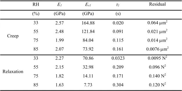
Table 1-1. Mechanical properties of LD C-S-H, HD C-S-H, and mix of C-S-H/CH by nanoindentation [14].
Phases M (GPa) H (GPa) C (GPa)
LD C-S-H 22.39 ± 4.84 0.61 ± 0.16 112.2 ± 23.3 HD C-S-H 34.82 ± 5.25 1.00 ± 0.21 182.5 ± 43.7 UHD C-S-H or Mix of C-S-H and C-H 47.53 ± 6.63 1.63 ± 0.38 342.6 ± 85.0
1.3 Alike C-S-H structures
Under the normal ambient temperature, the cement clinker reacts with water and the microstructure S-H is produced. However, there exists different application for which C-S-H transforms in a different more crystalline structure which is called tobermorite. Interestingly, such a structure has been considered a model structure to understand the one of C-S-H by several works [24,44–46]. Furthermore, tobermorite was found to be one of the phases of ancient roman concrete which has proven to be much durable as explained below [47].
In the industry of oil well cement, nevertheless, some of the cement sheaths are built under the ground and subjected to high temperature and pressure, e.g., up to 350 °C and high pressure up to 200 MPa [48]. Similarly, in the manufacture of autoclaved aerated concrete is cured above 150 °C [36]. With the addition of silica flour or quartz sand, C-S-H is transformed into various compounds of calcium silicate at the elevated temperature [49]. Most of these compounds can be found as minerals in nature. As shown in Figure 1-5, C-S-H gel has a various Ca/Si ratio, the average of which is approximately 1.7. At the temperature of 110 °C, C-S-H is converted to -C2S hydrate. The pure microstructure of this phase is
dense and crystallizes as rectangular plates [36]. However, -C2S hydrate is weak because
of its highly porous structure. To avoid the formation of -C2S hydrate, the addition of 35%
-40% silica flour reduces the Ca/Si ratio to 0.8 -1.0. A resilient microstructure of tobermorite is formed. It converts to xonotlite (C6S6H) when the temperature is elevated to above 150 °C.
During the process of autoclaved aerated concrete, aluminum powder is often added to generate the gas bubbles to reduce the density of the structure [50]. The presence of aluminum helps to accelerate the formation of tobermorite. A new microstructure of
Al-12
tobermorite is configured below the temperature of 175 °C which hinders the appearance of xonotlite [36].
Figure 1-5. Various formations of C-S-H [49].
The C-S-H structure is complex and amorphous, and it has generally been idealized as defected tobermorite structure with CH, or a formation of 1.4 nm tobermorite and jennite [51,52]. These alike microstructures have been frequently employed as the basic C-S-H model to study the mechanical property. Tobermorite and jennite are minerals found in nature. They are readily synthesized in the laboratory to study their mechanical behavior. Different portions of the reactants of calcium oxide (CaO), Silica (SiO2) and water were
mixed and cured to reach the corresponding Ca/Si ratio of tobermorite and jennite [53]. The chemical formula of 1.4 nm tobermorite with a layer thickness of 1.4 nm is (CaO)0.83(SiO2)(H2O)1.33 and that of jennite with a layer thickness of 1.05 nm is
(CaO)1.5(SiO2)(H2O)1.8. The two synthesized C-S-H structures: C-S-H (Ⅰ) and C-S-H (Ⅱ) are
defect structures of 1.4 nm tobermorite and jennite, respectively. In addition, the structure of jennite is closer to that of C-S-H than 1.4 nm tobermorite [36]. Notably, the layer distance of 1.4 nm tobermorite can be decreased to 1.1 nm at an elevated temperature of 90 °C and to 0.9 nm at 300 °C due to the loss of the interlayer water. The jennite may also undergo a similar structural shrinkage and be converted to metajennite at 90 °C [36,54]. The interlayer distance of jennite (1.05 nm) is condensed to 0.87 nm. The change of the condensed interlayer distance of jennite and tobermorite is described in Figure 1-6.
13
(a) (b)
Figure 1-6. Crystal structures of (a) jennite and (b) tobermorite [44,55].
Carbon dioxide (CO2) generated during the cement production is 1.46 Gt, ranking as the
third-largest source of global CO2 emission [56]. It is well known that CO2 is a greenhouse
gas. Increasing CO2 emission causes global warming, and subsequently brings unpredicted
disasters like floods and sea-level rise. In order to reduce the CO2 emission, supplementary
cementitious materials (silica fume, fly ash and slag) are introduced to replace the conventional cement paste. Different from ordinary cement paste, the microstructure of calcium-aluminum-silicate-hydrate (C-A-S-H) is also formed during the hydration with Aluminum-rich clinker [57]. Coupling the technique of nanoindentation and EDS, Wilson et al. [17] have recently characterized the mechanical property of the mix of C-A-S-H and S-H indicated by (A)-S-H. Their study shows that averaged mechanical properties of C-(A)-S-H are M=22-32 GPa, H=0.6-1.0 GPa, and C=145-275 GPa, which fall within the range of those for the LD C-S-H and HD C-S-H as summarized in Table 1-1. It is interesting that the poor crystalline C-A-S-H was also found in the ancient Roman marine concrete [58]. Incredibly, the seawater concrete has kept its integrity for more than 2000 years. The longevity of ancient concrete is phenomenal considering that modern concrete is designed to last for up to 100 years. The ancient Roman coincidentally constructed the mass concrete with alumina-rich volcanic ash made from pyroclastic rocks, which is similar to the fabrication of modern supplementary cementitious materials [47]. During the hydration, the crystalline C-A-S-H is also formed. It has been demonstrated that C-A-S-H, as shown in
14
Figure 1-7(b), plays a critical role in the long-term durability of the ancient Roman concrete [47]. During the continuous reaction with the seawater, C-A-S-H transforms to a rather resilient platy crystal of Al-tobermorite as shown in Figure 1-7(a). It remains to be determined how the Al-tobermorite crystallizes inside the ancient Roman concrete at a normal temperature because the synthesis of those materials in laboratory requires high temperature (200 °C) and confining pressure (30 MPa) [59]. Further research on the properties of crystalline Al-tobermorite may shed some light on improving the durability of modern concrete structures.
(a) (b)
Figure 1-7. SEM secondary electron image of (a) platy crystals of Al-tobermorite and (b) C-A-S-H and Al-tobermorite [47,58].
1.4 Effect of relative humidity on concrete creep
Creep is a phenomenon of the viscous materials for which strain occurs under sustained stress. Figure 1-8(a) shows an example of creep recovery experiment [23]. The uniaxial stress on concrete firstly leads to an instantaneous elastic strain. After that, the creep strain gradually increases while the creep rate decreases. Once unloaded, the rapid elastic recovery and the subsequent creep recovery representing the reversible creep are observed. The residual deformation at the end of the experiment is the irreversible creep. Corresponding to creep, concrete relaxation is a mechanical response that the stress decreases when the strain
15
is restricted to a constant. A number of external factors such as temperature, RH and stress level affect the concrete creep. As the artificial ‘water-stone’, concrete structures are continuously interacting with water during its lifespan. On one hand, the long-term hydration between the cement clinker and the water, known as concrete aging, promotes the stiffness and the strength of concrete and reduces creep deformation. On the other hand, the capillary pores exchange water in the ambient environment, which promotes the creep response. Being a formidable problem in concrete science, concrete creep has been widely investigated during the past century. In spite of the efforts by numerous researchers, the creep mechanism of concrete is still an enigma due to its complex microstructure. Phenomenologically, as shown in Figure 1-8(b), the concrete creep is associated with two mechanisms: the basic creep without the loss of moisture and the drying creep (i.e. Pickett effect) induced from surrounding drying processes [60,61]. It is generally acknowledged that the concrete creep is originated from the viscous slip of the H sheets [60,62,63], or rearrangement of C-S-H particles [13,31,64] for the basic creep, while the drying creep is associated with microcracking [65].
(a) (b)
Figure 1-8. (a) An example of uniaxial concrete creep [23]; (b) Shifted basic and drying concrete creep.
Among several factors that affect concrete creep, RH is considered to play an important role in concrete creep [66–68,68]. The pore humidity continuously interacts with the atmosphere which causes creep and shrinkage. In order to investigate the effect of RH on the concrete
16
creep, it is necessary to understand the various characteristic water distributed among the microstructures. According to a detailed report of Ishai [21,69], four types of water determined by their decreasing binding force to the solid phase are described as follows:
1. Interlayer water, one molecule thick ( 0.4 nm) water filling between the C-S-H sheets, part of which can be removed when the RH falls below 11%, part of the water is strongly and chemically adsorbed to the crystals, the removal of which requires an oven-drying process [33].
2. Hindered adsorbed water, two molecules wide ( 0.8 nm) adsorbed on the C-S-H surface and confined in between two adjoining C-S-H surfaces, which is present when RH is above 11%. Such water fills the narrowed space of two molecules in thickness between the adjacent C-S-H particles, producing the considerable disjoining pressure reaching up to 174 MPa according to the calculation by Bažant [70].
3. Water adsorbed to C-S-H surface with 1-2 molecule deep, which appears at the RH range between 11% and about 40-50% [22,33].
4. Large gel voids and capillary pores, where the free water beyond the range of Van der Waals force, present at the level of RH 40-50% or above for the first time, fully filling the gel pores and capillary pores at RH 85% and RH 100%, respectively [33]. Considering the results available in the open literature, the effect of RH or internal moisture on the creep behavior of concrete is controversial. A series of studies have adopted the disjoining pressure caused by hindered adsorption to explain the effect of RH on the concrete creep [60,71,72]. The increasing RH expands the narrowed space between the C-S-H particles, which reduces the disjoining pressure that is inversely proportional to the spacing between the stable films [73]. Some explanations focus on the adsorption of interlayer water between the C-S-H sheets. The increased interlayer water plays the role of lubrication. The amount of interlayer water increases with an elevated level of RH. Water of several molecules in thickness are expected to insert into the C-S-H layers [74]. The basal spacing between the C-S-H sheets expands subsequently, which weakens the Van der Waals forces and thus accelerates the creep [75]. There is experimental evidence showing that the creep strain
17
declines with the RH decreasing [76–78]. The creep was not observed when the evaporable water was depleted [79,80].
Compressive experiment on the concrete specimen with a diameter of 100 mm indicated that the drying creep is exhausted after one year, and the long-term creep compliance is mathematically logarithmic independent of the stored RH before testing [81]. Brooks [66] measured the creep and shrinkage of concrete at RH 65% and under saturated conditions lasting for five years. The creep rate of concrete specimen stored under saturated condition was significantly greater than the one stored in the dry condition. According to Bažant and Chern [82], the concrete creep rate is positively correlated to the internal pore humidity for the specimen kept in hygral equilibrium. They proposed an empirical factor which is a parabolic function in pore humidity, to correct the viscosity of the Maxwell chain model. Bažant et al.[83] then carried out the creep experiment at various levels of RH on a thin-walled concrete with a thickness of 0.71 mm, which is ready to reach hygral equilibrium. It was observed that the creep due to the increased RH was apparently accelerated at the lower range of RH (0-30%) and higher range of RH (50-90%). Nevertheless, Tamtsia and Beaudoin [67] argued that the basic creep of hardened cement paste is not affected by the moisture, but is only due to the micro-sliding of C-S-H particles.
Thanks to the development of indentation technology, it has been frequently employed to characterize the mechanical properties of cementitious materials. The properties of concrete microstructure are understood in more detail than before because of the indentation technique. It is worth noting that microindentation creep of hardened cement paste, which greatly reduces the testing time, is related to the macroscopic concrete creep. In particular, upscaling creep modulus of minutes’ microindentation creep is in good agreement with the creep modulus of macroscopic concrete creep lasting around 5 years [11]. In addition, the microindentation takes advantage of small probed volume which helps to reach a hygral equilibrium in a short time such as one day [10]. Microindentation on synthetic C-S-H by Zhang [84] showed that the contact creep modulus, which is inversely correlated to the long-term microindentation creep rate, went down to one-fifth when the RH is elevated from 11% to 95%. In other words, increasing RH promotes the creep, which is similar to the findings in the macroscopic creep experiment. In an RH controlled chamber, Frech-Baronet et al. [10]
18
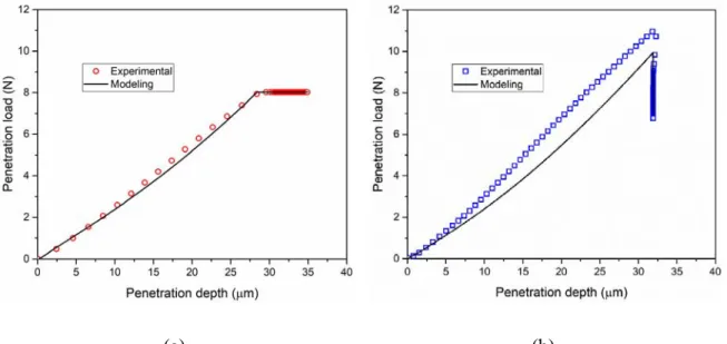
performed both the creep and relaxation microindentation tests on the hardened cement paste with a w/c of 0.6. As shown in Figure 1-9, the shifted penetration depth for the creep test and the shifted penetration load for relaxation test were presented. At the level of RH 18-55%, the effect of increased moisture on the microindentation creep is not significant. The viscoelastic response was accelerated when the RH is elevated to higher RH levels of 75-85%. However, to the best knowledge of the author, no study has been reported on the effects of increasing RH on the nanoscale mechanical properties of concrete microstructure through the nanoindentation testing.
(a) (b)
Figure 1-9. (a) Mean microindentation creep and (b) relaxation curves of cement paste (w/c=0.6) at various levels of RH [10].
1.5 Creep mechanisms
In order to understand the macroscopic concrete creep, many models about the time-deformation of C-S-H microstructure have been proposed [85]. Based on experimental observations, Feldman and Sereda [25] suggested the creep is due to water sorption and the mechanical properties of cement paste. As shown in Figure 1-10, the C-S-H is assumed to be a layered structure, i.e., similar calcium silicate sheet divided by interlayer space, which is filled by bridging silicate tetrahedra and hydrated water. C-S-H structure is similar to that of
19
tobermorite, but with more defects and amorphous nature [54]. Some water is physically adsorbed to the surface of the C-S-H sheets. Based on this model (which is shown in Figure 1-10), two creep mechanisms of C-S-H were suggested. Firstly, the reversible creep is due to a slow process of C-S-H decomposition and discharge of the interlayer water by the applied stress. The expelled water returns to its original position when the stress is unloaded in a reversible manner. Secondly, the irreversible creep originates from the sliding of a C-S-H sheet over the other one, followed a process of breaking and reconstruction of the interparticle bonds.
Figure 1-10. A model for the microstructure of C-S-H adapted from [25,86].
Differently, according to Powers [26,87], the phenomenon of concrete creep is partly due to the water adsorption and desorption. He proposed that the volumetric concrete creep, which is reversible, is associated with a process of water microdiffusion. The hindered adsorption between the microstructures is squeezed to the larger pores under the applied pressure as shown in Figure 1-11. The hindered adsorption between the narrowed space produces disjoining pressure. This pressure is disturbed and increased by the external load. The load-bearing water is subsequently squeezed to larger load-free pores such as large gel pores and capillary pores. Note that he assumed that the critical RH for the presence of capillary water is about 45% [26]. When the level of RH is below 45%, the water is more likely redistributed between the gel pores; when the level of RH is above 45%, the gel water is filled and is compressed to the capillary pores by the disturbed stress. This process is reversible. When the applied stress is relaxed, the disjoining pressure dilates the hindered space. The squeezed water can be return back to the original place when the external load is discharged. Interestingly, Powers’ hypothesis was recently validated by the measurement of a sudden
20
change of RH in capillary pores for a concrete sample at the loading [88]. The external load with a stress/strength ratio of 0.3 immediately gives a rise of 2% increase of the internal RH. This increase of RH disappeared as soon as the applied pressure was unloaded. Regarding the irreversible concrete creep, Powers proposed that it probably results from the formation of new primary bonds which are compacted together by the pressure as a sort of microstructure rearrangement [26]. The idea of breaking and remaking of bonds by the viscous flow is abandoned, because the cement paste is considered to be incapable of viscous flow.
Figure 1-11. Water diffusion of hindered adsorption in the smaller gel pores to the larger gel pores or capillary pores under the pressure, (a) initial state and (b) applied pressure, adapted from [88]. According to Wittmann [89], two mechanisms contribute to concrete creep: (1) the short-term creep is related to the water redistribution in the microstructures which is in line with Powers’ theory; (2) the long-term creep can be explained by the movement of numerous C-S-H gel particles. Macroscopically, it is similar to the dislocation of plastic materials. These particles are forced to leave their original position and assemble with adjacent particles. Based on the colloid structure of the aforementioned LD C-S-H, Jennings [31] also applied the mechanism of C-S-H particles rearrangement to explain the irreversible creep. Figure 1-12 presents a possible reconfiguration of the particles, one globule that contains some C-S-H particles moves and then the adjacent globule moves into the void that opens up. The dimension of concrete porosity ranges from nanometers to micrometers. The cement paste porous structure has sufficient empty space to accommodate the long-term movement of the particles.
21
From the view of granular mechanics, Vandamme and Ulm [13] studied the nanoindentation creep of three phases (LD, HD, and UHD) of C-S-H. The basic hypothesis of this study is that the C-S-H creep is due to the nano-particle sliding. Indeed, the fact that the cement paste creep is logarithmic in time is similar to what is generally observed in a wide range of granular materials [13], for which an increase in packing density occurs due to a sort of secondary consolidation. The movement gradually slows down when the packing density towards the limiting value. Finally, they concluded that the concrete creep is a process of rearrangement of C-S-H particles, which is in line with the research by Wittmann and Jennings. Recently, Morshedifard et al. [64] studied the nanoscale creep of C-S-H using the approach of molecular simulation. When the water content is increased, the C-S-H exhibits a transition from exponential to logarithmic creep. It was proposed that the C-S-H particle with lower water content indicated by H2O/SiO2 ratio shows viscoelastic behavior that can
be simulated with a standard linear model. Nevertheless, with higher water content, the C-S-H creep shifts to the logarithmic range due to the rearrangement of C-S-C-S-H nanoparticles [64].
(a) (b)
Figure 1-12. A schematic diagram of rearrangement of C-S-H particles (a) without and (b) with stress disturbance adapted from [31].
The drying creep (or Pickett effect) is an additional creep aside from the load-free shrinkage and the basic creep without moisture exchange. According to Bažant and Chern [90], it is a hygro-mechanical effect due to two mechanisms: one is the microcracking effect and the
22
other is called stress-induced shrinkage. When the load-free concrete specimen is exposed to the drying ambient environment, the surface moisture and the inner moisture are not uniform. The surface part shrinks faster than the inner part which leads to the tensile stress in the surface layer and the compressive stress in the inner layer. Because of the fact that the concrete tensile strength (ft) is far less than its compressive strength (fc) (ft 0.1 fc), the tensile
stress may cause a cracking surface of the specimen. The progressive cracking gives rise to a phenomenon of strain-softening and partly contributes to the drying creep [91]. The stress-induced shrinkage is related to a process of water microdiffusion. The applied stress accelerates the creep rate by locally promoting the transport from the gel pores to the capillary pores, and further boosting the moisture exchange between the capillary pores and the atmosphere [65].
1.6 Background of indentation
1.6.1 Basis of indentation
The modern indentation technology is attributed to the development of contact mechanics. Importantly, Sneddon [92] derived the closed relation between the penetration load and the depth by applying a series of Hankel transform. With the advantages of the small probed volume, non-destructive, fast and precise testing features, instrumented indentation gains an increasing application on the characterization of small-scale materials. As a landmark, Oliver and Pharr [18] improved the indentation technique by employing a Berkovich tip to determine two important parameters of the indentation modulus (M) and the indentation hardness (H) based on Sneddon’s solution. The error of the modulus tested on metal and glass samples is pronounced to be within 5% compared with the reference value. Figure 1-13(a) shows the schematic diagram of a typical load-depth (P-h) curve during the indentation testing. The plasticity is usually generated during the loading phase because of the high stress below the tip. For the indentation on the viscoelastic materials, the creep phenomenon that the indentation depth increases under the constant penetration load emerges.
The measurement of indentation modulus is based on the physical assumption that the initial unloading is elastic. The indentation modulusM of the indented material follows the relation [18,93]:
23 2 C S M A (1.1)
where is a correction factor which is in the function of Poisson’s ratio and accounts for the deviation of the pyramidal indenter tip caused by radial deformation [94],A is the contact C
area shown in Figure 1-13 (b), and S dP dh / h hmax is the slope at the outset of unloading. When the indentation is performed on relatively viscous material, a nose appears on the P-h curve. This effect leads to an overestimation of the slope Sand the indentation modulus. The real slope Sand the measured S are related in the following equation [95]: U
1 1 H U h S S P (1.2)
where hH dh t dtH( ) / is the rate of the penetration depth and P P max/U is the unloading rate. In order to minimize the creep effect on the measurement of the indentation modulus, two ways were suggested [95]: (ⅰ) To increase the unloading rate P , in other words, to set the unloading time U as short as possible with a constant P ; (ⅱ) To increase the holding max
time H because the creep rate hH gradually slows down with time growing.
The indentation modulusM , also called reduced modulus, is the combined modulus of the specimen and the tip, which is written as [96]
2 2 1 1 1 i i M E E (1.3) where Eis Young’s modulus of the sample,is the Poisson’s ratio of the sample, E =1141 i
GPa and i=0.07 are Young’s modulus and the Poisson’s ratio for the commonly used diamond tip, respectively. For the indentation on the cementitious materials, Eis far less
24 than E (i E(1/ 50)Ei). The term 1 2/
i Ei
can be negligible. Consequently, the indentation modulus is simplified to the plain strain modulus whereM E/1 . 2
(a) (b)
Figure 1-13. (a) Schematic illustration of indentation testing and (b) A typical curve of penetration load (P) versus penetration depth (h).
1.6.2 Viscoelastic indentation
Linear viscoelastic problem is usually controlled by the integral transform of stress and strain in mathematics. To analyze these time-dependent integral problems is sometimes implicit. Thus numerical scheme needs to be developed. The correspondence principle has the advantage that it can apply the viscoelastic problem to the well-established elastic theory by means of Laplace transform [97]. After the operation, the target problem is inversed to the form in the time domain. However, it is restricted to the monotonic boundary conditions. For instance, Lee and Radok [98] employed Laplace transform to solve the viscoelastic contact problems by substituting the elastic parameters with the transformed viscoelastic operators. The solution works when the contact area is increasing or constant but fails during the unloading phase when the contact area decreases. Ting [99] proposed an implicit solution for the arbitrary contact area (increasing or decreasing) in the function of time, while it is cumbersome to implement because of the complex integral formulas. For the analytical solution during the loading phase, the viscoelastic indentation by applying the Laplace transform to the Galin-Sneddon solution reads [19]:
![Table 1-1. Mechanical properties of LD C-S-H, HD C-S-H, and mix of C-S-H/CH by nanoindentation [14]](https://thumb-eu.123doks.com/thumbv2/123doknet/3188158.91055/26.918.174.744.153.272/table-mechanical-properties-ld-hd-mix-ch-nanoindentation.webp)