To link to this article : DOI : 10.7250/csimq.2016-7.05 URL : http://dx.doi.org/10.7250/csimq.2016-7.05
To cite this version : Rocha Silva, Thiago and Hak, Jean-Luc and Winckler, Marco Antonio An Approach for Multi-Artifact Testing Through an
Ontological Perspective for Behavior-Driven Development. (2016)
Complex Systems Informatics and Modeling Quarterly, vol. 7. pp. 81-107. ISSN 2255-9922
O
pen
A
rchive
T
OULOUSE
A
rchive
O
uverte (
OATAO
)
OATAO is an open access repository that collects the work of Toulouse researchers and makes it freely available over the web where possible.
This is an author-deposited version published in : http://oatao.univ-toulouse.fr/
Eprints ID : 18852
Any correspondence concerning this service should be sent to the repository administrator: [email protected]
An Approach for Multi-Artifact Testing Through an Ontological
Perspective for Behavior-Driven Development
Thiago Rocha Silva, Jean-Luc Hak and Marco Winckler
ICS-IRIT, Université Paul Sabatier, 118 Route de Narbonne, Toulouse, France {rocha, jean-luc.hak, winckler}@irit.fr
Abstract. In a user-centered development process, artifacts evolve in iterative
cycles until they meet users’ requirements and then become the final product. Every cycle gives the opportunity to revise the design and to introduce new requirements which might affect the specification of artifacts that have been set in former development phases. Testing the consistency of multiple artifacts used to develop interactive systems every time that new requirements are introduced is a cumbersome activity, especially if it is done manually. This paper proposes an approach based on Behavior-Driven Development (BDD) to support the automated assessment of artifacts along the development process of interactive systems. The paper uses an ontology for specifying tests that can run over multiple artifacts sharing similar concepts. A case study testing Task Models, Prototypes, and Final User Interfaces is presented to demonstrate the feasibility of this approach from the early phases of the design process, providing a continuous quality assurance of requirements, and helping clients and development teams to identify potential problems and inconsistencies before commitments with software implementation are made.
Keywords: Automated requirements checking, Behavior-Driven Development,
ontological modeling, prototyping, multi-artifact testing.
1
Introduction
It is a common understanding that in User-Centered Design (UCD) processes, users’ requirements and needs are not always identified at once, but, rather, they are revised/tuned and incrementally introduced along the multiple iterations through the use of Prototypes. When requirements are updated and/or new ones are introduced, the development team must cross-check their consistency with respect to artifacts that have been set in former development phases. Testing and tracing requirements during the development of an interactive system is an onerous task, especially because the development team has to deal with many cycles of iterations, multiple artifacts (such as Task Models, Prototypes, User Stories, Scenarios, etc.), and many design options for Prototypes that evolve until they reach the status of the Final Product. This cycle is represented in Figure 1.
Figure 1. The cycle of permanent evolution of artifacts in iterative processes
The traceability of artifacts can be classified as vertical and horizontal [1]. Vertical traceability describes the relationship between artifacts that can be derived from each other, for example from customer requirements to acceptance test cases. Horizontal traceability refers to the evolution of the same artifact. The artifacts traceability problem has been studied by several authors and a wide set of commercial tools have been developed to address this problem in various approaches [2]. Nonetheless, the solutions given by these tools to promote vertical traceability of artifacts can just track them among themselves, not allowing to effectively test them against requirements specifications.
Testing the consistency of artifacts with respect to user requirements is crucial for the quality of the software under development. Moreover, the sooner the teams pay attention to test their software components and especially their requirements specifications, more effective will be the results towards a quality assurance of the product. As argued by Lindstrom [3], failing to trace tests to requirements is one of the five most effective ways to destroy a project. Nonetheless, according to Uusitalo et al. [4], traceability between requirements and tests used to assess the implementation are rarely maintained in practice not only because of stringent enforcement of schedules and budgets, but also because it is difficult to update traces when requirements change and due to the difficulties to conduct testing processes manually.
In this context, Behavior-Driven Development (BDD) [5] has aroused interest from both academic and industrial communities in the last years. Supported by a development philosophy that includes Acceptance Test-Driven Development (ATDD) [6] and Specification by Example [7], BDD drives development teams to a requirements specification based on User Stories [8] in a comprehensive natural language format. This format allows specifying executable requirements, i.e., we can test requirements specifications directly, leading “live” documentation and making it easier for clients to set their final acceptance tests. It guides system development and gives an opportunity to test Scenarios directly in the User Interface with the aid of external frameworks for different platforms. However, this technique is currently limited to test requirements against a fully implemented user interface using specialized software robots. Besides that, specifications using only Scenarios are not self-sufficient to provide a concrete perception of the system to the users and, at the same time, allow an overall description of the
system in terms of tasks that may be accomplished. This is particularly true in early phases of the development process when the Prototypes are rudimentary samples of interactive systems.
In this paper we explore the use of BDD techniques for supporting automation of user requirements, testing a set of artifacts produced throughout the development process of interactive systems. Our ultimate goal is to test multiple artifacts throughout the development process looking for vertical and bidirectional traceability of functional requirements. To achieve this goal, a formal ontology model is provided to describe concepts used by platforms, models and artifacts that compose the design of interactive systems, allowing a wide description of User Interface (UI) elements (and their behaviors) to support testing activities. Whilst the approach is aimed at being generic to many types of artifacts, in this paper we have focused on Task Models, Prototypes and Final UIs. In the following sections we present the conceptual background, an overview of the underlying process for using the proposed approach and a case study that demonstrates its feasibility. Lastly we discuss related works and the next steps for this research.
2
Conceptual Background
In order to better explain how the proposed approach works, we present hereafter a summary of the basic concepts.
2.1 User Stories and Scenarios
A large set of requirements can be expressed as stories told by the user. Being a common activity in any requirements process, users and other stakeholders typically talk about their business process, emphasizing the flow of activities they need to accomplish. These stories are captured in requirements meetings and are the main input to formalize a requirements artifact. These meetings work mainly like brainstorm sessions and ideally include several stakeholders addressing different needs concerning features that may be developed. Iterative approaches capture these needs in successive meetings, according to the subject concerned in a particular iteration.
Nonetheless, the term User Story might have diverse meanings in the literature. In the Human-Computer Interaction (HCI) field, a User Story refers to an informal and fictional story describing users’ activities when performing typical tasks in a given domain. In Software Engineering (SE), User Story is the product of a conversation involving several people, especially when a business analyst talks to a business stakeholder about a feature or requirement, and helps them to frame it as a story narrative in agile projects. Below, we discuss the use of this term in both contexts.
User Stories and Scenarios in HCI. User Stories in HCI are a relevant source to identify
potential Scenarios in the users’ tasks. As stated by Lewis & Rieman, “…Scenarios forced us to get specific about our design, and it forced us to consider how the various features of the system would work together to accomplish real work…” [9]. It is close to the concept of Scenarios given by Rosson & Carroll [10] and widely used in UCD design. For Santoro [11], Scenarios provide informal descriptions of a specific use in a specific context of application, so a Scenario might be viewed as an instance of a use case, representing a single path through it. A careful identification of meaningful Scenarios allows designers to obtain a description of most of the activities that should be considered in a Task Model. Given Task Models have already been developed, Scenarios can also be extracted from them to provide executable and possible paths in the system.
Following an approach based on Task Models, interactive systems can be modeled to represent the flow of tasks that users should accomplish when using the system. For that purpose, Human-centered Assessment and Modeling to Support Task Engineering for Resilient Systems (HAMSTERS) [12] is a notation inspired by other existing ones for Task Modeling, especially
CTT [13], and has been designed to remain compatible with it (from the point of view of people building the models) as models are hierarchical and are graphically represented featuring operators between the tasks. However, HAMSTERS includes extensions such as pre-conditions associated with task executions, data flow across Task Models, and more detailed interactive tasks. HAMSTERS’ models can be edited and simulated in a dedicated environment which also provides a dedicated API for observing, editing, and simulating events, making it possible to connect Task Models to System Models [14], [15].
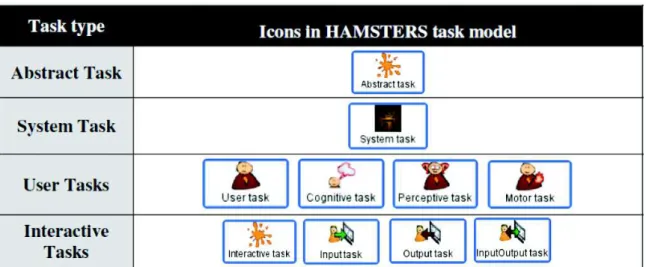
Table 1 illustrates some of the HAMSTERS’ constructs that are required for structuring models, including:
· Abstract task is a task that involves sub-tasks of different types. · System task is a task performed only by the system.
· User task is a generic task describing a user activity. It can be specialized as a Motor task (e.g. a physical activity), a Cognitive task (e.g. decision making, analysis), or Perceptive task (e.g. perception of alert).
· Interactive task represents an interaction between the User and the System; it can be refined into Input task when the users provide input to the system, Output task when the system provides an output to the user and Input/Output task which is a mix of both, but performed in an atomic way.
Table 1. Task types in HAMSTERS [12]
The notation also provides a composition mechanism to describe sub-routines. A sub-routine is a group of activities that a user performs several times, possibly in different contexts which might exhibit different types of information flows. The sub-routine is then modeled in a dedicated model where the root task is the icon of that sub-routine. A sub-routine contains:
· The name of the sub-routine.
· The icon of an “Abstract” task type (as the sub-routine consists of a group of tasks that can belong to different types).
· Specialized input and output ports attached both to the left side and to the right side of the icon. The graphical symbol of these specialized ports can be filled (if they handle parameters) or not (if they do not). These ports are mechanisms for representing required parameters to and/or from sub-routines, thus providing explicit representation of data flow during task execution.
Additionally, temporal relationships between tasks are represented by means of operators. The operator “Enable” (>>) describes that the tasks T1 and T2 occur sequentially, one after the other. The operator “Concurrent” (|||) describes that the tasks T1 and T2 can be performed
simultaneously. The operator “Choice” ([]) describes the user performing the tasks T1 or T2, but the choice of one implies that the other will be disabled. The operator “Disable” ([>) describes that the starting of the task T1 leads to a definitive interruption of the task T2. The operator “Suspend-resume” (|>) describes that the starting of the task T1 leads to a temporary interruption of the task T2; T1 can be restarted at any time and then be interrupted again by the task T2, while T1 is not complete. Finally, the operator “Order independent” (|=|) describes that the user can choose whether he will perform the tasks T1 or T2 first. This operator also indicates that the task selected to be executed first will be completed before moving to the next. It is the use of these operators to link tasks in the model that allows extracting of the possible Scenarios to be performed in the system. This is done by following the multiple achievable paths in the model, with each combination of them generating an executable Scenario.
User Stories and Scenarios in SE. The use of User Stories in SE was proposed by Cohn [8].
The author suggests to formalizing these stories in artifacts describing features and their acceptance criteria, with concrete examples about what should be tested to consider these features as “done”. For that, the stories are formatted to fulfill two main goals: (i) assure testability and non-ambiguous descriptions and (ii) provide reuse of business scenarios. Figure 2 presents a template proposed by North [16] and Cohn [8].
Title (one line describing the story) Narrative:
As a [role] I want [feature] So that [benefit]
Acceptance Criteria: (presented as Scenarios) Scenario 1: Title
Given [context]
And [some more context]...
When [event] Then [outcome]
And [another outcome]...
Scenario 2: ...
Figure 2. Template for specifying User Stories as defined by North [16] and Cohn [8]
According to this template, a User Story is described with a Title, a Narrative and a set of Scenarios representing the Acceptance Criteria. The Title provides a general description of the story, making reference to a feature that this story represents. The Narrative describes the referred feature in terms of the role that will benefit from the feature, the feature itself, and the benefit it will bring to the business. The Acceptance Criteria are defined through a set of Scenarios, each one with a Title and three main clauses: “Given” to provide the context in which the Scenario will be actioned, “When” to describe events that will trigger the Scenario and “Then” to present outcomes that might be checked to verify the proper behavior of the system. Each one of these clauses can include an “And” statement to provide multiple contexts, events and/or outcomes. Each statement in this representation is called Step.
In the Behavior-Driven Development (BDD) [5], the user's point of view about the system is captured by the User Stories, described according to the template shown in Figure 2. The BDD approach assumes that clients and teams can communicate using this semi-structured natural language description, in a non-ambiguous way (because it is supported by test cases).
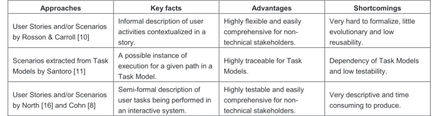
Referring to what was said above in this subsection, we can conclude that to some extent, the approaches mentioned agree that User Stories and Scenarios must provide a step-by-step description of tasks being performed by users using a given system. Nonetheless, there are some differences as illustrated by
Table 2. This analysis gives us the opportunity to establish a correlation between requirements identified in User Stories, their representation in terms of tasks and the extracted Scenarios in both UCD and SE approaches. We can notice that the main difference lies in the degree of formality and their possible value to support automated tests. Another remark we can make it is about the type of tasks mapped to Scenarios in SE. As SE considers only tasks being performed by users when using an interactive system, User Stories in this context address only Scenarios extracted from Interactive tasks in Task Models. Cognitive tasks, for example, are not mapped to be SE Scenarios because they cannot be performed in the system.
Table 2. Approaches for describing User Stories and Scenarios
Approaches Key facts Advantages Shortcomings
User Stories and/or Scenarios by Rosson & Carroll [10]
Informal description of user activities contextualized in a story.
Highly flexible and easily comprehensive for non-technical stakeholders.
Very hard to formalize, little evolutionary and low reusability.
Scenarios extracted from Task Models by Santoro [11]
A possible instance of execution for a given path in a Task Model.
Highly traceable for Task Models.
Dependency of Task Models and low testability.
User Stories and/or Scenarios by North [16] and Cohn [8]
Semi-formal description of user tasks being performed in an interactive system.
Highly testable and easily comprehensive for non-technical stakeholders.
Very descriptive and time consuming to produce.
2.2 Acceptance Testing of Functional Requirements
In this paper we are interested in testing functional requirements that users raise through the means of User Stories and Scenarios. In SE, the testing activity covers several levels of abstraction, from low level of tests such as Unit and Integration Testing to high level ones such as System and Acceptance Testing [17]. Low level tests are directly interested in the quality of the code produced which we call the White Box testing approach. On the other hand, high level tests are more interested in the quality of the final product as a whole which we call the Black Box testing approach. Tests can also be focused on specific aspects of the system such as Functional, Usability, Scalability or Performance.
Functional testing identifies situations that should be tested to assure the correct working of the system under development in accordance with the requirements previously specified. The Acceptance testing are tests made under the client/user point of view to validate the right behavior of the system. For that, clients might be able to run their business workflows and to check if the system behaves in an appropriate manner. Several techniques are employed to conduct functional testing such as Boundary Value Analysis, Equivalence Class Testing, Decision Table Base Testing, etc. [17]. These techniques support the development of test cases that might be specified to validate the right implementation of the requirements. They explore the expected behavior of the system when performing the software features as well as the potential error situations that could lead to inconsistencies in the software working.
The big challenge is that requirements are dispersed in multiple artifacts that describe them in different levels of abstraction. Thus, tests should run not only in the final product, but also in the whole set of artifacts to assure that they represent the same information in a non-ambiguous way and in accordance with the whole requirements chain. Moreover, testing should be performed along the development process as clients and users introduce new demands or modify the existing ones all along the iterations. Regression Testing is crucial to assure that the system remains behaving properly and in accordance with the new requirements. However, manual Regression Tests are extremely time consuming and highly error-prone. Therefore, automated tests are a key factor to support testing in an ever-changing environment, allowing a secure check of requirements and promoting a high availability of testing.
2.3 Computational Ontologies
According to Guarino et al. [18], computational ontologies are the means to formally model the structure of a system, i.e., the relevant entities and relations that emerge from its observation, and which are useful for our purposes. Computational ontologies come to play in this work as the means to formalize the vocabulary and the concepts used in User Stories, Scenarios and other artifacts during the development process of interactive systems. Without a common agreement on the concepts and terms used it would be difficult to support traceability of user requirements across many artifacts. Nowadays, some approaches have tried to define languages or at least a common vocabulary for specifying UIs in interactive systems. Despite the fact there is no such standard, a few approaches are worthy of mention, including DOLPHIN [19], UsiXML [20] and W3C MBUI Glossary [13]. DOLPHIN [19] is a reference framework that formalizes concepts around Task Models and, in particular, provides the means to compare Task Model notations. UsiXML (which stands for USer Interface eXtensible Markup Language) [20] is an XML-compliant markup language that describes the UI for multiple contexts of use such as Character User Interfaces (CUIs), Graphical User Interfaces (GUIs), Auditory User Interfaces, and Multimodal User Interfaces. UsiXML consists of a User Interface Description Language (UIDL) that is a declarative language capturing the essence of what a UI is, or should be, independently of physical characteristics. UsiXML describes at a high level of abstraction the constituting elements of the UI of an application: widgets, controls, containers, modalities and interaction techniques. More recently, W3C has published a glossary of recurrent terms in the Model-based User Interface domain (MBUI) [21]. It was intended to capture a common, coherent terminology for specifications and to provide a concise reference of domain terms for the interested audience. The authors’ initial focus was on Task Models, UI components and integrity constraints at a level of abstraction independent of the choice of devices to implement the models.
3
A New Approach for Multi-Artifact Testing
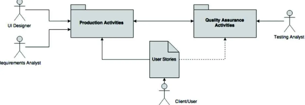
The proposed approach relies on the premise that user requirements expressed by the means of User Stories and Scenarios can be specified using the standard user interface ontology which allows testing automation against multiple artifacts throughout the development process of interactive systems. To explain how this could be, three figures (Figure 3, Figure 4 and Figure 5) are presented hereafter. Figure 3 illustrates User Stories supporting both Production Activities (which lead to the production of artifacts) and Quality Assurance Activities (aimed at assessing the artifacts produced during the development process). Clients, Users and Stakeholders are the main source of User Stories that will be used by Requirements Analysts and User Interface (UI) designers in Production Activities, and by Testing Analysts who are in charge of building test cases and assessing artifacts in Quality Assurance Activities. These roles were identified separately in order to emphasize that the activities along the process require different skills.
Whilst Figure 5 provides a workflow view of activities that have been grouped in Figure 3, Figure 4 highlights the major components and their interactions to accomplish requirements and testing specification. In Figure 4, User Needs are grouped with a specific icon to signalize that these needs can emerge from multiple sources such as business models, laws and regulations, demands indicated in brainstorm meetings, etc. Given that development teams can choose the artifacts that will be under testing in each iteration, the optional paths to test them are indicated by dotted lines.
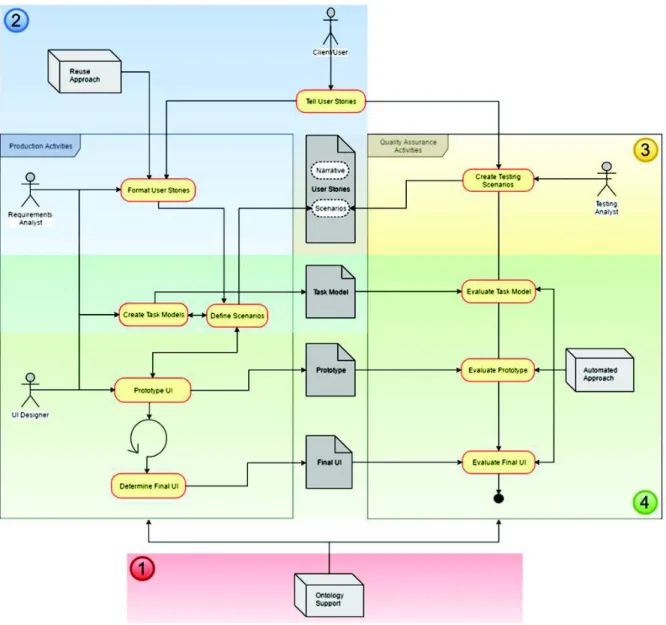
The operationalization of the approach is made up in four main steps that are pinpointed by numbers as follows: (1) definition of the ontology, (2) writing testable requirements, (3) adding test cases, and (4) multi-artifact testing. These steps are described herein.
Figure 3. Overall vision of the Requirements Model
Figure 4. Architectural View of the approach
To illustrate the operationalization of each step, we have proposed a case study in the flight tickets e-commerce domain in a traditional airline company, showing how the approach can support the testing of Prototypes and Final UIs. This case was chosen because it is easily comprehensible and we believe it represents a common activity for most of the readers. For the study, we have selected the American Airlines (AA) case to show these concepts. The AA model has been arbitrarily chosen to conduct this work. However, the core of business models for this kind of e-commerce is the same for all companies, so any other could have been chosen instead.
The online booking process of flight tickets is basically divided into 3 main sub-processes: searches of flights based on a provided set of data, the selection of the desired flight(s) in a list of flights resultant from the search, and finally providing passenger and payment data to conclude the booking. We have selected the first two processes for this study as they are the most interactive ones and represent the main source of cognitive efforts from users and designers. The third sub-process is basically a data providing form so it is not so relevant to demonstrate the concepts presented in the paper, even though the whole process can be supported by this approach.
Figure 5. Process View of the approach
3.1 Step 1: Definition of the Ontology
The proposed ontology is largely inspired from existing languages and vocabularies already described in Subsection 2.3, but to make it operational we have created an OWL (W3C Web Ontology Language) specification covering concepts related to the graphical components (presentation and behavior) used to build Web and Mobile applications. Figure 6 presents a general view of the ontology structure. We started modeling concepts describing the structure of User Stories, Tasks and Scenarios. Following this, we have modeled the most common Interaction Elements used to build Prototypes and Final User Interfaces (FUIs) in the Web and Mobile environments. The dialog component that allows us to add dynamic behavior to prototypes and navigation to FUIs was modeled as a State Machine (highlighted in Figure 6.b). In this level, a Scenario that runs on a given interface is represented as a Transition in the machine, while the interface itself and the one resultant from the action were represented as States. Scenarios in the Transition state always have at least one or more Conditions (represented by the “Given” clause), one or more Events (represented by the “When” clause), and one or more Actions (represented by the “Then” clause).
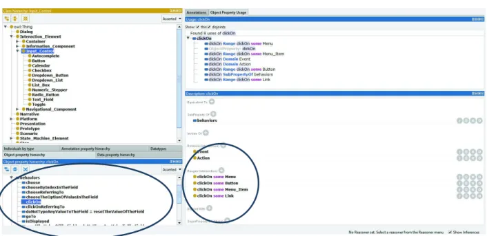
Figure 7 provides an example of how the behavior specification is defined, as well as how some classes are represented in the ontology. In the example, the behavior “clickOn” (see bottom-left side of the figure) has been associated with the Interaction Elements “Button”,
“Menu_Item”, “Menu” and “Link” to express that these ones are the elements that would be able to answer this behavior when it is triggered. The ontology also specifies that the behavior “ClickOn” is triggered by objects Action (“Then” clause) and Event (“When” clause). The top left side of the figure shows classes of a set of Interaction Elements classified by Containers, Information Components, Input Controls (dropped down in the figure) and Navigational Components.
Figure 6. Ontology representation: (a) Overall View, (b) State Machine Concepts
Figure 7. Ontology structure highlighting the definition of behaviors
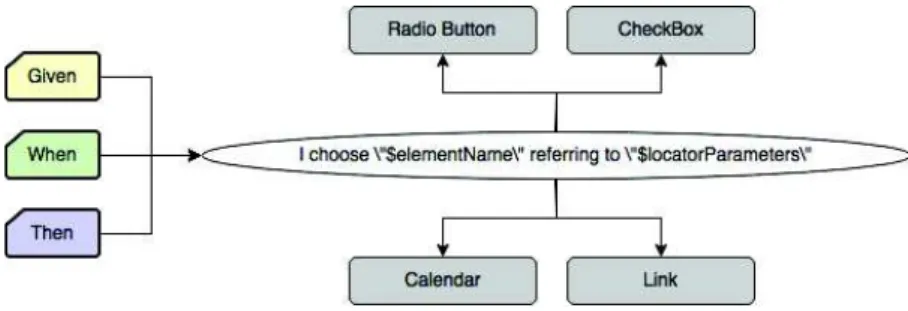
Figure 8 shows how a Behavioral Property (behavior of graphical components) is mapped to Interaction Elements (presentation of graphical components) of the ontology. Each behavior is suitable to receive (or not) two parameters as in the example “I choose $elementName referring to $locatorParameters”, and to be triggered by the clauses “Given”, “When” and/or “Then”. In the example, whilst the first parameter is associated to data for testing, the second parameter refers to the Interaction Element supported by this behavior: “Radio Button”, “CheckBox”,
“Calendar” and “Link”. The ontological model describes only behaviors that report Steps performing actions directly in the User Interface through Interaction Elements. We call it Common Steps (see Section 4.2). This is a powerful resource because it allows us to keep the ontological model domain-free, which means it is not subject to particular business characteristics in the User Stories, instigating the reuse of Steps in multiple Scenarios. Steps might easily be reused to build different behaviors in different Scenarios. Specific business behaviors should be specified only for the systems they make reference, not affecting the whole ontology.
Figure 8. Behaviors being mapped to UI Elements
Technically and with this structure, the current version of the ontology bears an amount of 422 axioms, being 276 logical axioms, 56 classes, 33 object properties, 17 data properties and 3 individuals.
3.2 Step 2: Writing Testable Requirements
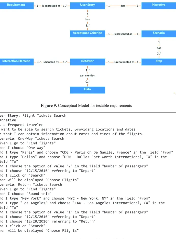
The approach is focused on functional requirements. A functional requirement defines statements of services that the system should provide, how the system should react to particular inputs and how the system should behave in particular situations. To assure that the system behaves properly, requirements should be expressed in a testable way. Figure 9 presents the conceptual model that explains how testable requirements are formalized in the proposed approach. A requirement is expressed as a set of User Stories (US) as in the template proposed by North [16] and Cohn [8] and presented in Subsection 2.1. User Stories are composed by a Narrative and a set of Acceptance Criteria. Acceptance Criteria are presented as Scenarios and are composed by at least three main Steps (“Given”, “When” and “Then”) that represent Behaviors which the system can answer. Behaviors handle actions on Interaction Elements in the User Interface (UI) and can also mention examples of data that are suitable for testing them. Notice that these concepts and rules are defined as classes and axioms in the ontology shown in Section 3.1.
Hereafter, we present two User Stories with their respective Scenarios to describe and test the features of our case study. Figure 10 presents the User Story for searching flights in which the user should provide at least: the type of ticket he wants (one-way or round trip), the airport he wants to depart from and arrive at, the number of passengers, and finally the date of departure and return. In the first Scenario (“One-Way Tickets Search”), a typical search of tickets is presented concerning a one-way trip from Paris to Dallas for 2 passengers on 12/15/2016. According to the business rule, the expected result for this search is a new screen presenting the title “Choose Flights”, in which the user might select the desired flight from a list of flights matching his search. The second Scenario (“Return Tickets Search”) simulates a round trip from New York to Los Angeles for only 1 passenger, departing on 12/15/2016 and returning on 12/20/2016. For this case, the same behavior is expected from the system, i.e., a new screen presenting the title “Choose Flights”, in which the user might select the desired flight from a list of flights matching his new search.
Figure 9. Conceptual Model for testable requirements User Story: Flight Tickets Search
Narrative:
As a frequent traveler
I want to be able to search tickets, providing locations and dates So that I can obtain information about rates and times of the flights.
Scenario: One-Way Tickets Search
Given I go to "Find flights" When I choose "One way"
And I type "Paris" and choose "CDG - Paris Ch De Gaulle, France" in the field "From" And I type "Dallas" and choose "DFW - Dallas Fort Worth International, TX" in the field "To"
And I choose the option of value "2" in the field "Number of passengers" And I choose "12/15/2016" referring to "Depart"
And I click on "Search"
Then will be displayed "Choose Flights"
Scenario: Return Tickets Search
Given I go to "Find flights" When I choose "Round trip"
And I type "New York" and choose "NYC - New York, NY" in the field "From"
And I type "Los Angeles" and choose "LAX - Los Angeles International, CA" in the field "To"
And I choose the option of value "1" in the field "Number of passengers" And I choose "12/15/2016" referring to "Depart"
And I choose "12/20/2016" referring to "Return" And I click on "Search"
Then will be displayed "Choose Flights"
Figure 10. User Story for Flight Ticket Search formatted for the testing template
The User Story that selects the desired flight(s) is given in Figure 11. The Scenario “Select a diurnal flight”, using the Scenario “One-Way Tickets Search” already executed, simulates the selection from the list of available flights, of a couple of diurnal flights, AA6557 and AA51. In this case, the behavior expected from the system is the presentation of a new screen with the
“Optional log in” message, indicating the user is able to log in in order to proceed to the booking, filling the passengers and payment data.
User Story: Select the desired flight Narrative:
As a frequent traveler
I want to get the list of flights and their rates and times
So that I can select the desired flight after a search of available flights.
Scenario: Select a diurnal flight
One-Way Tickets Search
Given "Flights Page" is displayed
When I click on "Flights" referring to "AA flight 6557, AA flight 51" Then "Optional log in" is displayed
Figure 11. User Story for Select the desired flight formatted for the testing template
3.3 Step 3: Adding Test Cases
Test Cases are represented as Testing Scenarios that specify potential error situations related to the Scenarios already defined to set Requirements. Testing Scenarios are the component responsible for describing the situations in which the system should be verified, covering, as deeply as possible, the largest set of features. Thereby, Scenarios and Testing Scenarios compose the User Stories, providing in the same artifact descriptions of functionalities as well as the potential tests to verify the correct implementation of the requirements. Functional testing is the leading element of the acceptance level, the Black Box approach is used to check expected outcomes when predefined inputs are provided to the system. Figure 12 shows the Scenarios “Search for flights more than one year in advance” and “Search for a return flight before a departure flight” that will be added to the User Story “Flight Ticket Search”. They present specific business rules (and their tests) in the flight-booking domain. The expected outcome in both cases is the impossibility of searching for flights.
Scenario: Search for flights with more than one year in advance
Given I go to "Find flights" When I choose "One way"
And I type "Paris" and choose "CDG-Paris Ch De Gaulle, France" in the field "From" And I type "Dallas" and choose "DFW-Dallas Fort Worth International, TX" in the field "To"
And I choose the option of value "1" in the field "Number of passengers" And I try to choose "12/15/2017" referring to "Depart"
Then the system should not allow performing this task
Scenario: Search for a return flight before a departure flight
Given I go to "Find flights" When I choose "Round trip"
And I type "New York" and choose "NYC-New York, NY" in the field "From"
And I type "Los Angeles" and choose "LAX-Los Angeles International, CA" in the field "To"
And I choose the option of value "1" in the field "Number of passengers" And I try to choose "12/15/2016" referring to "Depart"
And I try to choose "12/10/2016" referring to "Return" Then the system should not allow performing this task
3.4 Step 4: Multi-Artifact Testing
The execution of testing in multiple artifacts is shown in Figure 13. The top part presents the Step of a Scenario describing the behavior “choose … referring to …”. In the example, a user chooses the date of departure “12/15/2016” on the field “Depart” in a form. This task is triggered when an event “When” occurs in the Scenario. This task is associated with values for date of departure (“12/15/2016”) and the field (“Depart”), indicating a possible executable Scenario that can be extracted from that task. Following the ontology, the behavior addressed by this task can be associated with multiple UI elements such as Radio Button, CheckBox, Link and Calendar components. The arrows in the right side of the figure indicate two implementations of this ontology, highlighting these associations. First in OWL version at the top and then converted in Java code at the bottom.
Figure 13. Identifying behaviors through multiple artifacts
When the UI element Calendar is chosen by the UI designer to address this behavior, a locator is triggered to trace this element throughout the artifacts, thus allowing us to reach it for testing purposes. Figure 13 shows this trace being made through a HAMSTERS Specification for Task Models [12] (in the task “Choose Depart”), through a UsiXML Specification for Prototypes [20] (Calendar “Depart”), and finally through a Java Specification for Final UIs (@ElementMap “Depart” with the XPath reference “//input[@id=’departSelect’]” in a Calendar).
Testing Prototypes and Final UIs. For the purposes of the illustration, when testing the User
Story “Flight Tickets Search”, Figure 14 presents the mapping of a Prototype and Figure 15 the mapping of a Final User Interface.
Figure 16 and Figure 17 present respectively the mapping of the Prototype and the Final UI for the User Story “Select the desired flight”.
Finally, the tests by a robot of the business rules “Search for flights more than one year in advance” and “Search for a return flight before a departure flight” is presented in Figure 18. This behavior could have been implemented in several ways on the User Interface. The chosen solution by developers was to block the inappropriate dates in the calendar according to the business rules.
Figure 14. The “Find Flights” Prototype Figure 15. The “Find Flights” Final UI
Figure 16. The “Choose Flights” Prototype Figure 17. The “Choose Flights” Final UI
Figure 18. An attempt to select a return date before the departure date
Testing Task Models. The testing of Task Models is demonstrated by the use of HAMSTERS
models. Task Models in this case can support the development of User Stories and/or be tested by them. To illustrate this operationalization, below in Figure 19 and Figure 20, we present the HAMSTERS Task Models to represent the User Stories “Flight Tickets Search” and “Select the desired flight”.
Considering the set of possible Scenarios that can be extracted from these Task Models, we can establish a correlation between requirements identified in User Stories, their representation in terms of tasks and the extracted Scenarios in both UCD and SE approaches, as stated in Subsection 2.1. A possible solution for this mapping, considering two Scenarios, and in accordance with the proposed ontology is presented in Table 3 and Table 4.
Figure 19. Task Model for the User Story “Flight Tickets Search”
Figure 20. Task Model for the User Story “Select the desired flight”
Table 3. The correlation between Requirements, Tasks and Scenarios in UCD and SE approaches for the
User Story “Flight Tickets Search”
Requirement Task
Scenario Extracted from Task Models
(UCD approach)
Written in the BDD template (SE approach)
Travelers should be able to search for flights
Narrative:
As a frequent traveler, I want to be able to
search tickets, providing locations and dates, So that I can obtain
information about rates and times of the flights.
Search Flights
(abstract task) - Scenario: One-Way Tickets Search Request for Providing
Data (output task)
First the system request for the traveler to provide data for searching flights
Given I go to "Find flights"
Choose Trip Type (input task)
Then the traveler chooses the
trip type When I choose "One way" Inform Departure
(abstract task)
Then the traveler informs the departure location
And I type "Paris" and choose "CDG - Paris
Ch De Gaulle, France" in the field "From" Inform Destination
(abstract task)
Then the traveler informs the destination
And I type "Dallas" and choose "DFW -
Dallas Fort Worth International, TX" in the field "To"
Inform Number of Passengers (input task)
Then the traveler informs the number of passengers
And I choose the option of value "2" in the
field "Number of passengers" Inform Dates
(input task)
Then the traveler informs the travel dates
And I choose "12/15/2016" referring to
"Depart" Submit the Search
(input task)
Then the traveler submits the search
And I click on "Search"
Present the List of Available Flights (output task)
Then the system provides a list of flights to be chosen
Then will be displayed "Choose Flights"
Choose Flights (sub-routine)
Table 4. The correlation between Requirements, Tasks and Scenarios in UCD and SE approaches for the
User Story “Select the desired flight”
Requirement Task
Scenario Extracted from Task Models
(UCD approach)
Written in the BDD template (SE approach)
Travelers should be able to select available flights
Narrative:
As a frequent traveler, I want to get the list of
flights and their rates and times, So that I can
select the desired flight after a search of available flights.
Choose Flights
(sub-routine) - One-Way Tickets Search
Choose Flights
(abstract task) - Scenario: Select a diurnal flight Request for Choosing a
Flight (output task)
First the system request for the traveler to choose a flight
Given "Flights Page" is
displayed Evaluate the Availability of
Flights
(cognitive analysis task)
Then the traveler evaluates which flight is the most suitable for him
-
Choose the Desired Flight (cognitive decision task)
Then the traveler decides which flight is the most suitable for him
-
Select the Desired Flight (input task)
Then the traveler selects the desired flight
When I click on "Flights"
referring to "AA flight 6557, AA flight 51"
Request for Login (output task)
Then the system request for the traveler to optionally log in
Then "Optional log in" is
displayed
Analyzing these correlations, we can make a set of important remarks:
1. The business value (represented in orange in the Narratives) and the testing component (represented in purple in the BDD Scenario) allow us to implement test cases to validate the envisioned requirement, as well as checking when, after being implemented, this feature can be considered as “done” and correct (that correspond to the business value being achieved).
2. Concerning the type of tasks mapped to Scenarios in SE, as SE considers only tasks being performed by users when using an interactive system, User Stories in this context address only Scenarios extracted from Interactive tasks in Task Models. As highlighted in red in Table 4, Cognitive tasks, for example, are not mapped to SE Scenarios because they cannot be performed in the system.
3. The abstract tasks “Inform Departure” and “Inform Destination” highlighted in blue in Table 3 were detailed in the Task Model as a sequence of Input/Output Interactive tasks. This happens because first the user informs a departure/destination city (Input task “Inform City”), then the system returns a list of airports in this city (Output task “Provide List of Airports”), and finally the user selects the desired airport (Input task “Select the Airport”). This behavior is typically represented by the Interaction Element AutoComplete in the UI design, in which the user types some text and the element dynamically returns a set of values that matches it. After that, the user is able to choose which value he wants. Because of that, this behavior was represented with the Step “…type and choose…” in the SE Scenario, thus describing a double action in the UI.
4. The sub-routine “Choose Flights” was represented in the first model (User Story “Flight Tickets Search”) as a result of the sequence of user tasks, and then detailed in the second model (User Story “Select the desired flight”). As the second User Story depends on the execution of the first one, the sub-routine was represented in the SE Scenario as a reference for the Scenario “One-Way Tickets Search” that has just been performed. Thereby, the results of the User Story “Flight Tickets Search” allow the choice of flights in the User Story “Select the desired flight”.
5. Scenarios extracted from Task Models do not consider data for execution. On the other hand, SE Scenarios need these data to perform tests in the UI. Therefore, in the Task Modeling level, tasks are described in a generic way, as in the Input task “Choose Trip Type”, for example. When these tasks evolve to the Test Modeling level, they need to
receive an example of some representative data in that context, as in the Step “When I choose “One way”, for example. For testing purposes, when describing SE Scenarios, it is crucial to design them with data that make the results succeed as well as with data that make the results fail. It is the mechanism (exemplified in Subsection 3.3) that makes it possible to bring a large and representative testing component for the requirements. These data can be provided for SE Scenarios by multiple sources as described in Subsection 4.2.
…
<task copy="false" critical="0" folded="false" help="" id="1" iterative="false" maxexectime="0" minexectime="0" name="Search Flights" nb_iteration="0"
optional="false" type="abstract" x="439" y="19"> <operator id="2" type="enable" x="488" y="111">
<task copy="false" critical="0" folded="false" help="" id="18"
iterative="false" maxexectime="0" minexectime="0" name="Request for Providing Data" nb_iteration="0" optional="false" type="output" x="-166" y="210"/>
<task copy="false" critical="0" folded="false" help="" id="19" iterative="false" maxexectime="0" minexectime="0" name="Choose Trip Type" nb_iteration="0" optional="false" type="input" x="9" y="210"/>
<task copy="false" critical="0" folded="false" help="" id="4" iterative="false" maxexectime="0" minexectime="0" name="Inform Departure" nb_iteration="0" optional="false" type="abstract" x="135" y="210">
<operator id="11" type="enable" x="77" y="315">
<task copy="false" critical="0" folded="false" help="" id="10" iterative="false" maxexectime="0" minexectime="0" name="Inform City"
nb_iteration="0" optional="false" type="input" x="-127" y="390"/>
<task copy="false" critical="0" folded="false" help="" id="12" iterative="false" maxexectime="0" minexectime="0" name="Provide List of Airports" nb_iteration="0" optional="false" type="output" x="9" y="390"/>
<task copy="false" critical="0" folded="false" help="" id="13" iterative="false" maxexectime="0" minexectime="0" name="Select the Airport" nb_iteration="0" optional="false" type="input" x="170" y="390"/>
</operator> </task>
<task copy="false" critical="0" folded="false" help="" id="5" iterative="false" maxexectime="0" minexectime="0" name="Inform Destination" nb_iteration="0" optional="false" type="abstract" x="262" y="210">
…
</task>
<task copy="false" critical="0" folded="false" help="" id="20"
iterative="false" maxexectime="0" minexectime="0" name="Inform Number of Passengers" nb_iteration="0" optional="false" type="input" x="398" y="210"/>
<task copy="false" critical="0" folded="false" help="" id="21" iterative="false" maxexectime="0" minexectime="0" name="Inform Dates" nb_iteration="0" optional="false" type="input" x="601" y="210"/> <task copy="false" critical="0" folded="false" help="" id="22" iterative="false" maxexectime="0" minexectime="0" name="Submit the Search" nb_iteration="0" optional="false" type="input" x="720" y="210"/>
<task copy="false" critical="0" folded="false" help="" id="23" iterative="false" maxexectime="0" minexectime="0" name="Present the List of
Available Flights" nb_iteration="0" optional="false" type="output" x="849" y="210"/>
<task copy="false" critical="0" folded="false" help="" id="9" iterative="false" maxexectime="0" minexectime="0" name="Choose Flights" nb_iteration="0" optional="false" type="subroutine" x="1094" y="210"/> </operator>
</task> …
Figure 21. Task Model for the User Story “Flight Tickets Search” represented as an XML file with the
Figure 21 and Figure 22 detail how the tasks in the Task Models are identified in their respective XML files for testing purposes. Using tools like JUnit and directly parsing these XML files, we succeed in verifying if each one of the Steps in the Scenarios that refers to the input of data by users (normally represented by the “When” clause) can be mapped to a proper Input task in the Task Model. Likewise, we verify that each one of the Steps in the Scenarios that refers to output of data by the system (normally represented by the “Then” clause) can be mapped to a proper Output task in the Task Model. Lastly, the Operator type described in the Task Models (“Enable” in the examples) is the element that allows us to verify the right sequence of tasks when performing SE Scenarios.
…
<task copy="false" critical="0" folded="false" help="" id="1" iterative="false" maxexectime="0" minexectime="0" name="Choose Flights" nb_iteration="0"
optional="false" type="abstract" x="383" y="23"> <operator id="7" type="enable" x="433" y="113">
<task copy="false" critical="0" folded="false" help="" id="4"
iterative="false" maxexectime="0" minexectime="0" name="Request for Choosing a
Flight" nb_iteration="0" optional="false" type="output" x="-107" y="187"/>
<task copy="false" critical="0" folded="false" help="" id="3"
iterative="false" maxexectime="0" minexectime="0" name="Evaluate the Availability
of Flights" nb_iteration="0" optional="false" type="cognitive_analysis" x="118"
y="187"/>
<task copy="false" critical="0" folded="false" help="" id="5"
iterative="false" maxexectime="0" minexectime="0" name="Choose the Desired Flight" nb_iteration="0" optional="false" type="cognitive_decision" x="354" y="187"/> <task copy="false" critical="0" folded="false" help="" id="6"
iterative="false" maxexectime="0" minexectime="0" name="Select the Desired Flight" nb_iteration="0" optional="false" type="input" x="553" y="187"/>
<task copy="false" critical="0" folded="false" help="" id="8" iterative="false" maxexectime="0" minexectime="0" name="Request for Login" nb_iteration="0" optional="false" type="output" x="730" y="187"/>
</operator> </task>
…
Figure 22. Task Model for the User Story “Select the desired flight” represented as an XML file
with the components for testing highlighted
Finally, when building Task Models, we know that in the beginning of the process, requirements are more declarative and lead to User Stories in a high level of abstraction. As the project evolves, Scenarios descriptions become more refined and closer to the actions on the expected interface. Chelimsky et al. [5] call them declarative and imperative Scenarios. These two styles of writing tell the same Stories, but at different levels of abstraction. That impacts different parts of the process in different ways. The first style is more horizontal, wrapping several activities up into a single Step, which means it generally supports more Scenarios, covering a larger set of features, but with fewer Steps definitions. This style is represented by the abstract tasks “Search Flights” and “Choose Flights”. Conversely, the second style tends to be more vertical and customized to each Scenario, with Steps going step-by-step through performing each Interaction Element in the interface. It means that the work of writing Steps definitions spreads out more throughout the development, benefiting the development of test cases. This style is represented by the I/O (Input/Output) tasks presented in the models.
4
Tool Support
This section presents a technical description about how tests are implemented on the interaction level in both Prototypes and Final UIs artifacts. For operationalizing the test we employ tools like WebDriver, JBehave and JUnit. Nonetheless, in order to run and integrate tests into the development process of Prototypes and Final UIs, other tools also have been developed.
4.1 Testing in the Prototype Level
For the test in the Prototype Level, we have developed a prototyping environment named PANDA (Prototyping using Annotation and Decision Analysis). The development of a Prototype using this tool is made thanks to a toolbar containing widgets automatically generated from the OWL ontology as described in Subsection 3.1. Once the toolbar is generated, the user can create his Prototype by placing widgets, whose properties are described in the ontology and presented in the edition area as illustrated in Figure 23. Using this technique allows mapping between the elements described in the ontology (and thus, their properties and supported behaviors) and each of the widgets of the Prototype.
A PANDA Prototype features a state machine where states of the system are populated with the elements in the display when the state is active. By linking states with transitions it is possible to specify the structure and the behavior of the Prototype. After having developed the Prototype, it is possible to replace a transition with a Scenario. Indeed, in Figure 23 we have a testing Scenario used as a transition in the state machine. This Scenario links together the state “Find Flight” represented by the rectangle with a gray header in the upper part of the Prototype with the state “Choose Flight” located in the lower part. The state “Find Flight” represents the initial condition (indicated by the “Given” clause) and the state “Choose Flight” represents the result of the Scenario execution (indicated by the “Then” clause).
PANDA supports Scenarios described in a text format which are imported in the editing area. When importing a Scenario, PANDA parses the different Steps and analyzes them by identifying the events, the tasks, the associated values and the targets of the task, as illustrated in Figure 13 in Subsection 3.4. This identification is done by splitting each line of the Scenario and identifying keywords like “Given” or “Then” and the quote character. Quoted segments are interpreted as values except for the last quoted element of each line, which is identified as the target of the task. Segments before the quoted elements are considered as actions related to the values read. Each line read is then registered as a Step of the Scenario. Figure 24 shows an example for the Step “And I type ‘Paris’ and choose ‘CDG – Paris Ch De Gaulle, France’ in the field “From”. The value “Paris” is associated with the action “I type”, “CDG – Paris Ch De Gaulle, France” is associated to the action “choose” and “From” is associated with the locator “in the field”. Keywords are ignored except for the word “Given” and “Then” which introduce conditions and the final actions.
And I type "Paris" and choose "CDG - Paris Ch De Gaulle, France" in the field "From"
Figure 24. Example of a split Step during the parsing
Once the Scenario has been parsed and attached between an initial and a resultant state, it can be executed in order to find out if the Scenario is supported by the Prototype. This execution can be made step-by-step or with the whole set of Steps of the Scenario being executed at the same time. PANDA checks the state in which the prototype is, as well as the properties defined in the ontology loaded. Thereby, it verifies if each Step of the Scenario is able to be run according to the set of supported tasks. To do so, the system starts by mapping between the widgets of the Prototype and the target of the tasks during the execution, since Scenarios and states of the Prototype are independent. For the moment, this mapping is based on the name of the widget, but other mapping methods will also be considered. Then, for each Step whose target has been mapped, the system checks if each action or property matches with the properties of the widget which were defined in the ontology. As an example, in the Step “And I click on “Search”, PANDA looks for any widget named “Search” in the initial state, and checks if the description of the corresponding widget in the ontology supports the behavior “clickOn” (see Figure 25).
Figure 25. Properties of a button in the tool
PANDA with properties defined by the ontology
Figure 26. Example of results given during a
Scenario testing
The results of the tests are displayed by a colored symbol next to each Step as shown in Figure 26. A red “X” represents failure, a green “V” represents success, and a black “?” represents an untested Step. There is currently no distinction between the different reasons for test failure (e.g. widget not found, property not supported, etc.). In our example, the button
supports the event “#clickOn” which matches with the action “I click on” of the Scenario. However, none of the UI Elements (Calendar, CheckBox, Link or Radio Button) described in the ontology to support the behavior “chooseReferringTo” was found.
In a prototyping context, the automated interface testing could be used as a way to validate a version of a Prototype that passes the tests, or points out parts of the Prototype that require attention and further analysis, for example. PANDA is focused on the evolution of a Prototype, as signalized by the evolutionary cycle in the process workflow shown in Figure 5. Thereby, the same Scenario can be used on different versions of the Prototype, until the Prototype reaches the Final UI.
4.2 Testing in the Final UI Level
To test the Final UI directly from User Stories, we use external frameworks (the so-called robots) to provide automated execution in the Final UI. Robots mimic user interactions with the Final UI by running Scenarios described in the User Stories. We use the robot Selenium WebDriver to run navigational behavior and JBehave and Demoiselle Behave to parse the Scenario script. Test results provided by the JUnit API indicate visually which tests are passed and which ones failed and why. Execution reports of User Stories, Scenarios and Steps can be obtained by using the JBehave API.
Figure 27 presents the architectural model integrating tools and classes in the approach for testing the Final UI. The ontological model described in Section 3.1 provides a pre-defined set of behaviors used at the Requirements Layer. Artifacts produced in Prototyping and Task Layers are suitable to not only benefit from the ontology description to model better requirements, but also to contribute with the development of new User Stories. Pre-defined behaviors are mapped by the CommonSteps class that supports the development of specific behaviors not covered by the ontology that will be subsequently mapped in the MySteps class. Both Steps are extracted from the User Stories that can be represented in simple packages of text files. This structure composes the Requirements and Testing Layer. The Presentation Layer includes the MyPages class that describes the link between UI components defined in the ontology and the real UI components instantiated on the interface under testing. This link is crucial to allow the Selenium WebDriver robot and the other External Testing Frameworks to automatically execute the Scenarios in the right components on the UI. Finally, the MyTest class is a JUnit class in charge of triggering the tests, pointing which Scenarios should be executed and making the bridge between UI components in the Presentation Layer and executable behaviors in the Requirements and Testing Layer. Figure 28 shows the MyTest class automatically executing the Scenario “Return Tickets Search” presented in the case study.
Concerning the testing data, the approach offers two main strategies to set test data out of Scenarios. The first one is establish Data Providers to store values for variables that can be used when writing Steps of Scenarios. This mechanism is useful to render flexible the reuse of data dynamically and to hide data in Scenarios without losing readability. The second mechanism is the use of data storage in XML files. It is useful to work with a large set of data that should be introduced in Scenarios at runtime. Figure 29 and Figure 30 illustrate these mechanisms.
Figure 27. Architectural representation of automated testing in the Final UI
Figure 28. Automated execution of the Scenario “Return Tickets Search”
dataProvider.put("valid date", "12/30/2016"); (a)
And I choose "valid date" referring to "Depart" …
<DataSet>
<dataRecords>
<DataRecord id="Europe USA"> <dataItems>
<DataItem key="Number of passengers" value="2" /> <DataItem key="Depart" value="12/15/2016" /> </dataItems>
</DataRecord>
<DataRecord id="Inside USA"> <dataItems>
<DataItem key="Number of passengers" value="3" /> <DataItem key="Depart" value="12/31/2016" /> ...
</DataSet>
(a)
... When I provide the value of the field "Number of passengers" And I provide the value of the field "Depart" ...
(b)
Scenario: Search of flights stored in the dataset When I search for flights "Europe USA"
Then "Choose Flights" is displayed When I search for flights "Inside USA" Then "Choose Flights" is displayed
Figure 30. Data stored in an XML file: (a) data associated to XML file, (b) reference to dataset
5
Related Works
Efforts to specify requirements in a natural language, such as Language Extended Lexicon (LEL) [22], have been studied since the 90’s. The authors propose a lexical analysis of requirements descriptions in order to integrate Scenarios into a requirements baseline, making possible their evolution as well as the traceability of the different views of the requirements baseline. Nonetheless, the requirements specified through an ATDD approach are recent in academic discussions. For example, Soeken et al. [23] propose a design flow where the designer enters in a dialog with the computer where a program processes, sentence by sentence, all the requirements creating code blocks such as classes, attributes, and operations in a BDD template. The template proposed by the computer can be revised; which leads to a training of the computer program and a better understanding of following sentences. Some works [22], [23] use different approaches to process natural language; nonetheless, none follow a User-Centered Design process.
Wolff et al. [24] proposes linking GUI specifications to abstract dialogue models. Specifications are linked to Task Models describing behavioral characteristics. Prototypes of interactive systems are refined and interactively generated using a GUI editor. The design cycle goes from Task Model to abstract user interfaces and finally to a concrete user interface. It is an interesting approach to have a mechanism to control changes in interface elements according to the task to which they are associated in the Task Models. However, the approach is not iterative and does not provide the necessary testing component to check and verify user interfaces against predefined behaviors from requirements.
Martinie et al. [25] propose a tool-supported framework for exploiting Task Models throughout the development process and even when the interactive application is deployed and used. The framework allows connecting Task Models to an existing, executable, interactive application, thus defining a systematic correspondence between the user interface elements and user tasks. The problem with this approach is that it only covers the interaction of Task Models with Final UI, not covering other types of possible requirements artifacts that can emerge along the process. Another problem is that it requires much intervention by developers to prepare the

![Figure 2. Template for specifying User Stories as defined by North [16] and Cohn [8]](https://thumb-eu.123doks.com/thumbv2/123doknet/3107977.88212/6.892.100.812.455.700/figure-template-specifying-user-stories-defined-north-cohn.webp)