Science Arts & Métiers (SAM)
is an open access repository that collects the work of Arts et Métiers Institute of
Technology researchers and makes it freely available over the web where possible.
This is an author-deposited version published in: https://sam.ensam.eu
Handle ID: .http://hdl.handle.net/10985/12000
To cite this version :
Hatem AMDOUNI, Hassen BOUZAIENE, Alex MONTAGNE, Adrien VAN GORP, Thierry COOREVITS, Mustapha NASRI, Alain IOST - Experimental study of a six new ball-burnishing strategies effects on the Al-alloy flat surfaces integrity enhancement - Int. J. Adv. Manuf. Technol - Vol. 90, p.2271-2282 - 2017
Any correspondence concerning this service should be sent to the repository Administrator : archiveouverte@ensam.eu
ORIGINAL ARTICLE
Experimental study of a six new ball-burnishing strategies effects
on the Al-alloy flat surfaces integrity enhancement
Hatem Amdouni1&Hassen Bouzaiene2&Alex Montagne3&Adrien Van Gorp3&
Thierry Coorevits3&Mustapha Nasri1&Alain Iost3
Received: 26 June 2016 / Accepted: 25 September 2016 # Springer-Verlag London 2016
Abstract In the literature, the most studies conducted on the flat surface ball-burnishing process have been focused on the most important classical factors like burnishing speed, lateral feed, and the ball-burnishing load or pressure on the treated surfaces integrity enhancement. In this research, ball-burnishing strategies are studied as a new ball-ball-burnishing fac-tor. The aim of this research is to show the improvement of the flat surface integrity of 2017A-T451 aluminum alloy using six new ball-burnishing strategies. Ball-burnishing tests were conducted in two passes using the recommended values of the ball-burnishing factors (the penetration depth ab is
40 μm, the linear ball-burnishing speed Vbis 500 mm/min and a lateral feed f of 0.2 mm). Two ball-burnishing strategies in two successive and perpendicular passes to the machining direction and four ball-burnishing strategies in two crossed passes have been designed and tested to improve the flat sur-faces integrity of the samples. The characterization and the micrographic observations of the ball-burnished surfaces show that using the best ball-burnishing strategy leads to a great enhancement in surface quality. The latter is predicted by a gain in average roughness Ra of 81 %, an improvement in the mean spacing of profile irregularities Sm of 34 %, an enhancement in surface Nano-hardness HIT of 17 %, and sub-layer hardness betterment up to a depth of 500μm. Keywords Ball-burnishing strategy . Roughness . Nano-hardness . SEM micrograph . Aluminum alloy
1 Introduction
Ball-burnishing process is a mechanical surface treatment, eventually used for the finishing of functional mechanical sur-faces [1]. It is widely practiced following the machining of the cylindrical surfaces [2], spherical [3], concave or convex [4], flat [5,6], or complex surfaces [7] of mechanical parts. This post-machining and low-cost finishing process is often ap-plied to improve the surface integrity of aluminum alloys, which are difficult-to-grind with the high-cost conventional grinding as mentioned in the work of El-Axir et al. [8]. In addition, as a solution of the latter problem, Bouzid et al. have shown that the ball-burnishing surface treatment process can easily replace grinding in the machining range of the mechan-ical part production [9].
This mechanical surface finishing technology without material removal consists in the crash of the surface
* Hatem Amdouni hatemamdouni@gmail.com Hassen Bouzaiene bouzaiene.hassen@gmail.com Alex Montagne alex.montagne@ensam.eu Adrien Van Gorp adrien.vangorp@ensam.eu Thierry Coorevits thierry.coorevits@ensam.eu Mustapha Nasri Mustapha.Nasri@isetn.rnu.tn Alain Iost alain.iost@lille.ensam.fr 1
Laboratoire de Photométrie, IPEIN, BP 62 Merazka, 8000 Nabeul, Tunisia
2 Research Units in Solid Mechanics, Structures and Technological
Development (99-UR11-46), ENSIT, Tunis, Tunisia
3
Arts et Métiers ParisTech, MSMP, 8 boulevard Louis XIV, 59000 Lille, France
Int J Adv Manuf Technol DOI 10.1007/s00170-016-9529-9
geometric irregularities roughness under the effect of a normal pressure applied by a rigid rolling or sliding ball against the machined surface as shown in Adnan Akkurt study, inducing thereby a cold plastic deformation of the roughness peaks and pushing them into the hollow of the surface roughness profile [10]. So, this process makes smooth and hard the machined surface as indicated in the work of Hassan (1997) and eliminating at the same time the potential priming sites of cracks (the roughness hollow) [11]. In addition, by forming an incompatibility of plastic deformation between the surface and the rest of the mate-rial part, a compressive residual stresses are formed to a depth of up to 1 mm in depth as investigated in the research conducted by Hassan and AI-Wahhab in 1998 [12].
As for the other shapes of surface, the successful applica-tion of the ball-burnishing process in order to improve the flat surface integrity needs the mastery, the study, and the optimi-zation of several factors related to the mechanical surface treatment technology as shown in the literature survey and discussion paper of Loh and Tam [1]. The most significant factors studied by researchers for the flat surfaces finishing by ball-burnishing are in order of interest, feed rate or the overlap or also called lateral feed, the penetration depth, and the linear burnishing speed which are the necessary factors for the flat surface sweeping.
With a second interest, several other process-related factors have been studied by researchers namely ball material, ball diameter, lubricant, ball-surface contact pressure, kind of the ball-surface contact, initial roughness of the machined surface, the normal burnishing load, the number of passes, and the surface sweeps strategy (ball-burnishing tool path).
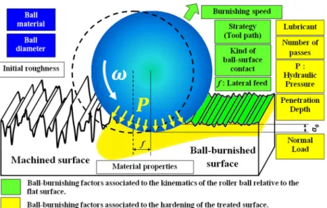
A classification of the flat surface ball-burnishing fac-tors is proposed in Fig. 1. The latter show that all ball-burnishing factors related to the finishing process can be classified in four groups. The first one is formed by the ball-burnishing factors associated to the kinematics of the roller ball relative to the flat surface such as burnishing speed, lateral feed, kind of ball/surface contact, and the ball-burnishing strategies (tool path). The second is asso-ciated to ball-burnishing factors necessary for the harden-ing of the flat treated surface namely penetration depth, the normal load, hydraulic pressure, the number of passes, and lubricant. The third group is formed by the ball-burnishing factors associated to the ball characteristics like ball diameter and ball material. Finally, the fourth group is associated to the treated surface propriety as the initial roughness and material properties.
The measurable responses of the treated surfaces by ball-burnishing such as hardness and roughness are non-linear [13]. Then, the optimization of these mechanical greatness is necessary in each application of the process to establish the optimum ball-burnishing factors giving the better surface integrity. By using the Taguchi
Method, an optimization with experimental design of a freeform surface roughness of plastic injection mold was established by Shiou and Chen for studying the con-tribution of the four ball-burnishing process factors (ball material, burnishing speed, burnishing force, and feed rate) on the finished surface roughness [14]. Afterward, optimal conditions were applied on a pocket mold sur-face. Then, average roughness enhancement was established about 63 % for the flat surface and 78 % for free-form surface.
Loh et al. have shown that ball material, lubricant, lat-eral feed, and depth of penetration are the significant fac-tors at a 99 % confidence level on the roughness enhance-ment by ball burnishing of the flat surfaces of AISI 1045 steel specimens [15]. The application of optimal process factors has allowed the team to achieve a 400 % improve-ment in the treated surface roughness. The machined sur-face roughness of 4 μm (Rtm) was finished by ball bur-nishing to 0.772 μm.
As shown in their work, Salahshoor and Guo have used the ball-burnishing process on flat samples to improve the corrosion resistance of the biodegradable magnesium-calcium (MgCa) alloy, often used in the manufacture of dental implants [16]. They showed that the roughness of the burnished surfaces is anisotropic. This anisotropy in-creases with the increasing of burnishing pressure and burnishing lateral feed. The lower anisotropy and the best roughness are obtained by applying a ball-burnishing strategy designed with two crossed passes. In this case, ball-burnishing process has been applied under medium pressure, with a low lateral feed and a slow burnishing speed. A much improvement of the ball-burnishing sur-faces micro-hardness ranges from the surface to 500 μm of the subsurface. Unlike roughness, surface hardness is isotropic. The increase in burnishing pressure causes the decrease in surface hardness, while the rolling speed, the lateral feed, and burnishing strategy have poor effects. Also, an additional pass degrades the surface hardness by chipping formation.
The application of the ball-burnishing process for surface finishing of P20 heat-treated steel (often used in the manufac-ture of molds and dies) and Inconel 718 has allowed López de Lacalle et al. to get a high-quality mirror-like surface (Ra = 0.071 μm) [3]. The lowest arithmetic roughness Ra is obtained when the ball burnishing is applied at perpendicular direction to milling.
So, the mechanical cold work hardening of the surface, the great improvement of the surface roughness, the in-creasing in micro-hardness surface, and the introduction of compressive residual stress in sub-layers are the sources of surface integrity gains. The latter is described by an improvement in the fatigue strength, an increase in corrosion resistance as demonstrated in Prevéy et
Cammett publication [17]. In addition, a tribological be-havior betterment of the treated surfaces described by the enhancement of the wear resistance of mechanical parts has been shown in the work of Hassan et al. [18]. Furthermore, the ball-burnishing load, which is responsi-ble for the surface and sub-layer hardening of the treated surface as indicated in Rodríguez et al. work [19], is the major factor affecting the improvement of the wear resis-tance of the samples steel as demonstrated in the study of Rajasekariah and Vaidyanathan [20]. Also, a wear in-crease was observed by Neema and Pandey in the case of excessive increase in the load and number of passes during the ball burnishing of metallic surfaces [21].
In this process, there is an interaction between the ball diameter and the burnishing applied load. An in-crease in the ball diameter coupled with the inin-crease in ball-burnishing load leads to a deterioration of the treated surfaces predicted by the increase in roughness and degradation of the surface hardness and therefore, consequently, an increased surface wear as shown in Hassan and Maqableh study [22].
Generally improving fatigue life, wear, and corrosion resis-tance is the result of the improvement of the treated flat sur-faces integrity through research, mastering, and optimization of significant ball-burnishing factors. Great interests in the influence study of the classical ball-burnishing factors (lateral feed, burnishing speed, and the depth of penetration) were given by researchers to improve the flat surfaces integrity. Moreover, only one study has compared the effect of using two ball-burnishing strategies for finishing flat surfaces as shown in Salahshoor and Guo study [16]. The authors have shown that ball-burnishing strategy in two crossed ZIG/
ZAG passes has greater potential in improving the flat sur-faces integrity than that of the two successive and perpendic-ular ZIG/ZAG passes to machining direction.
In addition in their work, Amdouni et al. have conducted a modeling and an optimization study of a new ball-burnishing strategy, in two crossed passes, to investigate the influence of three classical ball-burnishing factors (burnishing speed, depth of penetration, and lateral feed) on the 2017A-T451 aluminum alloy flat machined surface integrity enhancement [13]. Optimized surface has led to mirror-like surface quality charac-terized by an improvement in average roughness Ra of 81 %, an enhancement in the mean spacing of profile irregularities Sm of 34 %, and a gain in surface nano-hardness HIT of 17 %.
This existing gap in the literature for the study of the ball-burnishing strategy effects is explained by the use of a single pass for the finishing of flat surfaces in the most research on this subject as indicated in Shiou and Hsu [23] In this study, we reveal the influence of the application of six new ball-burnishing strategy for improving the aluminum alloy flat surfaces integrity.
2 Experimental work
2.1 Specimen preparation and ball-burnishing operations Experimental work conducted in this study has the objective of the application of six ball-burnishing strategies on a flat machined surface. Then, a plate of size 1290 × 310 × 10 mm of a 2017A-T451 aluminum alloy of which chemical composi-tion and mechanical characteristics are shown in Tables1and2
was used.
Fig. 1 Flat surface ball-burnishing factors classification
As shown in Fig.2, the machining of 85 × 60 × 10-mm size sample and the surface treatment by ball-burnishing, according to the parameters shown in Table 3, was per-formed on the same three axes CNC machining center SPINNER VC650. A ball-burnishing tool providing a rolling contact between the rigid ball of 14 mm of diam-eter and the flat machined surface was designed as shown in Fig.2a, b. The circular pocket in which are housed five intermediate balls underwent a hard chrome coating to improve friction and to avoid the balls wear. In addition, as shown in Fig.2a, the contact between the five interme-diate balls (5) and the circular pocket surfaces as well as that between the five intermediate balls (5) and the main ball (4) are greased using the bearing K2K-30 grease in accordance with the standard DIN 51825.
The surfaces quality evaluation of the machined and the ball-burnished ones are done by the measurements of rough-ness plots parameters using the optical interferometric profilometer Veeco Wyko NT9300 according to the Standard ISO 4287, (1997) for Geometrical Product Specifications (GPS). Furthermore, the evaluation of the sur-face hardness and hardness sub-layer gradient of the six ball burnished surfaces as well as that machined, nano-indenter XP MTS was used in classic mode indentation in charge-dis-charge. This device enables to indent the surface of the sample to be characterized with a Berkovich tip of high rigidity. The dry machining of the flat surface was conducted with a cutter milling tool having a 63 mm as a diameter and equipped with a three reported carbide inserts (TCMT 110204) with a fre-quency spindle N = 960 rpm, a feed rate fm= 384 mm/min, a depth of penetration af= 0.4 mm, a tooth feed-rate fz = 0.08-mm/r.tooth and a cutting speed Vc = 190 m/min.
Successively, on the same machining center CNC, six ball-burnishing strategies, of size 20 × 20 mm, developed in Fig. 3 were applied on the machined flat surface fol-lowing the recommended and optimum ball-burnishing factors (the linear ball-burnishing speed Vb = 500 mm/ min, the penetration depth ab= 40μm, and a lateral feed f = 0.2 mm) as shown in Fig. 4 and as investigated in Amdouni et al. study [13].
2.2 Design of six ball-burnishing strategies
Whatever the number of passes applied for finishing a flat surface by ball-burnishing, the final finishing pass must be applied perpendicular to the machining direction of the treated surface as mentioned in the works of Sequera et al. [6] and Salahshoor et al. [16]. In each ball-burnishing pass on the flat machined surfaces, the rolling without slipping of the ball can be practiced in two different cycles previously programmed on the CNC machining center.
During the cycle named ZIG/ZAG which is the most used by researchers [23], the roller ball keeps contact with the machined surface for a ZIG/ZAG scanning by making a back and come movement as shown in the work of Salahshoor et al. [16]. But, a different cycle called SEUIL can be practiced only in one direction while losing the contact between the ball and the surface during the lateral movement phase.
The finishing possibility of flat surfaces by ball-burnishing using two different cycles of the ball displacement available on the machining center CNC has allowed us to imagine the six ball-burnishing strategies as shown in Fig.3.
& Strategy 1: strategy ZIG/ZAG in two perpendicular suc-cessive passes to the milling direction of the flat surface (X-axis).
& Strategy 2: strategy SEUIL in two perpendicular suc-cessive passes to milling direction of the flat surface (X-axis).
& Strategy 3: Strategy ZIG/ZAG in two crossed passes, a first parallel pass followed by a second perpendicular pass to the cutting direction (X-axis).
& Strategy 4: Strategy SEUIL in two crossed passes, a first parallel pass followed by a second perpendicular pass to the cutting direction (X-axis).
& Strategy 5: Strategy SEUIL_ ZIG/ZAG in two crossed passes, a first parallel SEUIL pass followed by a sec-ond perpendicular ZIG/ZAG pass to the cutting direc-tion (X-axis).
Table 1 Chemical composition
of 2017A-T451 aluminum alloy Chemical composition of 2017A-T451
Elements Al Si Fe Cu Mn Mg Cr Zn Zr + Ti Others total
wt% Rest 0.76 0.7 3.82 0.54 0.67 0.1 0.25 0.25 0.15
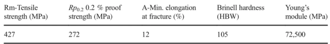
Table 2 Mechanical properties
of 2017A-T451 aluminum alloy Rm-Tensile
strength (MPa) Rp0.20.2 % proof strength (MPa) A-Min. elongation at fracture (%) Brinell hardness (HBW) Young’s module (MPa) 427 272 12 105 72,500
& Strategy 6: Strategy ZIG/ZAG_ SEUIL in two crossed passes, a first parallel ZIG/ZAG pass followed by a second perpendicular SEUIL pass to the milling direction (X-axis).
3 Results
3.1 Surface roughness
The five times repetition of the surfaces roughness parameters were measured along the X- and the Y-axis of both ball-burnished and machined surface as shown in Fig.4. Then, ball burnished surfaces were compared to that machined in the same direction as shown in Fig. 5a for X-axis and Fig.5b for the Y one. Comparing the roughness parameters Ra, Rq, Rz, and Rt of ball-burnishing flat surfaces to that machined along the surface cutting direction show that: & All ball-burnishing strategies in two passes practiced on flat
surfaces are able to improve the roughness parameters mea-sured according to the cutting direction of the samples.
& All tested surfaces show that the roughness parameters measured in the X direction are greater than those mea-sured along the perpendicular direction; this is due to the anisotropy of the initial surface finish (machined surface). & Comparison of both ball-burnishing strategies in two suc-cessive and perpendicular passes to the machining direc-tion reveals that the strategy (2) is better than strategy (1) in reducing the surface roughness of the machined surface. & By exception of the strategy (3), the ball-burnishing strat-egies in two crossed passes have better potential for im-proving the roughness than the first two successive strat-egies. Strategy (6) has the best capability for reducing and improving surface roughness.
& The best potential improvement of roughness carried out with the strategy (6) results in a gain of 81 % for Ra, 84 % for Rq, 82 % for Rz, and 81 % for Rt.
Tested surfaces roughness anisotropy was quantified by the difference between the roughness parameter values measured in the X direction of machining and those along the perpen-dicular direction. The latter represented in Fig.6shows that
Fig. 2 Experimental setup: a ball-burnishing tool design, body (1), screw (2), blocking screw (3), principal ball 14 mm of diameter (4), and five intermediate balls 7 mm of diameter (5); b ball-burnishing tool mounted on CNC Milling Collet Chuck (6); and c application of ball-burnishing process, CNC Vise Clamps (7) and sample (8)
Table 3 Milling and ball-burnishing flat surface experimental parameters
Milling flat surface Ball-burnishing of machined surface
Parameter Symbol Quality Parameter Symbol Quality
Face milling cutter diameter Df 63 mm Ball material Chromed 100Cr6
Three carbide inserts TCMT 110204 Ball diameter Øball 14 mm
Spindle frequency N 960 r/min Contact ball/surface Rolling
Feed rate fm 384 mm/min Number of passes NP 2
Penetration of cut af 0.4 mm Burnishing speed Vb 500 mm/min
Feed per tooth fz 0.08 mm/tooth Depth of penetration ab 40μm
Cutting speed Vc 190 m/min Lateral feed f 0.2 mm
the strategy (6) gives the lowest anisotropy roughness among the tested surfaces.
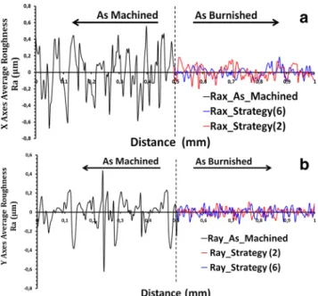
Figure7shows that both ball-burnishing strategy (2) and (6) are able to improve the arithmetic roughness of the ma-chined surface profile Ra by crushing the roughness picks and pushing them by plastic deformation in the hollow. Thereby, they improve the surface roughness and remove in the same time the maximum potential future priming sites of surface cracks (hollow) which is predicted by the reduction of the mean spacing of profile irregularities Sm.
Figure 8 shows that all strategies are able to improve the roughness parameter Sm along both X- and Y-axes, but the best contribution is assigned to the strategy (6) along the X-axes. The application of this strategy has been able to reduce the mean spacing of machining profile irregularities along the X-axes from 35.48μm in to 23.18 after finishing, that is to say a gain of 35 %. In addition to the strategies (2), (4), and (5), the strategy (6) remains among the best to improve the roughness Sm variable along the Y-axis by reducing it from 27.09 μm for machined surface profil to 17.1μm after treatment, i.e., an enhancement of 37 %.
Each ball-burnishing strategy developed in this research has its own potential and power to reduce the peaks and
Fig. 3 Design of the six ball-burnishing strategies
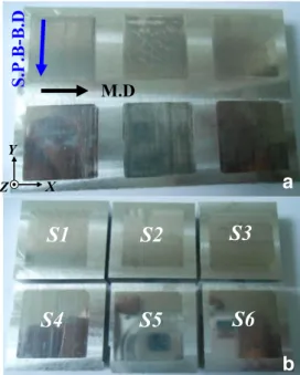
a
b
Fig. 4 Samples preparations: a application of the six ball-burnishing strategies, the second pass ball-burnishing direction (S.P.B-B.D), the milling direction (M.D); and b separation of the six ball-burnishing strategies for surface characterizationsroughness hollows. That is to say, each strategy work hard-ened machined surface in a way different from other strategies and depends on the kind of ball-burnishing used strategy.
3.2 Surface hardness 3.2.1 Superficiel hardness
The instrumented Martens Hardness test was conducted in this study under the parameters indicated in Table 4 and was used for the measurements of macro surface hardness of the tested surfaces Fig. 9.
The measurements show that all ball-burnishing strategies developed in this study are able to improve the macro surface hardness of the machined surface. Ball-burnishing strategies (1) and (2) in two successive and perpendicular passes to the ma-chining direction have a better potential for hardening of the machined surfaces that the strategies in two crossed passes.
The strategy (6) is the best of cross strategies which give surface macro hardness comparable to that given by the two strategies in two successive passes perpendicular to the
a
b
Fig. 5 Comparison of roughness parameters of treated surfaces with six different ball-burnishing strategies, a along the X-axes and
b along theY-axes
Fig. 6 Roughness parameters anisotropy of treated surfaces with six
machining direction. For a load about 50 N, the gain in macro surface hardness is successively 42 % for strategy (1), 39 % for strategy (2), and 35 % for strategy (6). This indicates that the strategy (6) resists nearly in the same way as the two non-crossing strategies (1) and (2) to the indenter penetration.
3.2.2 Sublayers hardness
The evaluation of the hardness gradient in the sub-layer of both ball-burnishing and machining surfaces was carried by the nanoindentation tests which have been performed with a XP MTS instrument (USA) mounted with a three sided pyra-mid (Berkovich tip). The tip area function has been calibrated using a reference material of known modulus (fused quartz, E = 72 GPa). Load-displacement curves have been analyzed using the Oliver and Pharr method [24]. The loading profile used was as follows: a first load at 500 mN in 30 s, then a
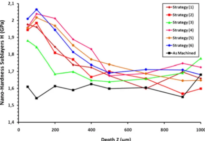
dwelling time of 12 s to avoid creep effect during the unloading part, and finally, an unloading part to 0 mN in 30 s. Nano-hardness measurements were carried out at a depth of 1 mm as shown in Fig.10. The results show that:
✓There is no change in hardness for the machined surface along a depth of 1 mm under layer (1.6 GPa).
✓All burnishing strategies developed in this study provide a clear and significant improvement in hardness layer extend-ing over a depth of 500μm.
✓Besides strategy (3), burnishing strategies in two crossed passes (4), (5) and (6) are better than the two strategies in two successive passes (1) and (2) in their improvement hardness under-layer of ball burnished surfaces.
✓At the depth of 100 μm, the strategy (6) acquires the highest sub-layer hardness material (2.07 GPa).
4 Discussion
4.1 Ball-burnishing strategies effects on surface roughness The machined surface texture and topography are a result of the nature of the used cutting tool and cutting condi-tions mentioned above in Table 3. During machining of
Fig. 9 Macro-hardness surface H (GPa) for different charge applications
Table 4 Martens hardness test parameters
Martens hardness test
Parameters Qualities
Determining mode of zero-point Second-degree polynomial
Load 50 N, 100 N, 200 N
Waiting time at the load point 12 s
Speed of the contact point 1 mm/min
Charge velocity 100 N/min
Discharge velocity 100 N/min
Deformability machine 0.0049679μm/N
Fig. 8 Contribution of the six ball-burnishing strategies on the improvement of the mean spacing of profile irregularities Sm
Fig. 7 Comparison of the average roughness profiles of the ball-burnished surface with strategies (6) and (2), and the machined surface,
the surface, the material tearing forms roughness peaks and hollows. Then, the observed machining marks take the shape of arches which are periodically spaced in the feed direction of cutting tool (Fig. 11 (M)). These latter are the white arches observed in the micrograph of the
machined surface Fig. 12 (M). The white arcs are a not ripped flakes formed during the cutting phase of the ma-terial surface. They remain attached to the roughness peaks which are characterized by their low mechanical strength (Fig. 12(M)).
Therefore, they can be cold work-hardened during an under pressure rigid element passage. This is the reason for what the machined surface roughness profile is called a saw-tooth or a “jaggedness” texture as men-tioned in Salahshoor and Guo study [16]. Then, the roughness peaks form a mechanically weakest geometric link of the roughness profile able to be deformed plas-tically and then pushed into hollows.
This geometrical irregularity of the machined surface roughness profile is reduced and eliminated by all ball-burnishing strategies developed in this research. So, that is the reason for what we notice the total elimination of white arches in Fig.12. As a result, a higher light reflection capabil-ity is given to treated surfaces by ball burnishing, and then, we obtain mirror-like surfaces as shown in Fig.4. But, we also note that except strategy (6) (Fig.12(S6)), in which all traces
Fig. 11 Surface texture, As Machined (M), strategy 1 (S1), strategy 2 (S2), strategy 3 (S3), strategy 4 (S4), strategy 5 (S5), and strategy 6 (S6). M.D
milling direction, S.P.B-B.D second pass of ball-burnishing direction Fig. 10 Nano-hardness sublayers of treated and machined surfaces
are practically striped, the rest of ball-burnishing strategies fail to remove the cutting tool marks.
By exception of the strategy (3), the ball-burnishing strategies in two crossed passes developed in this work have unequal reducing power of geometrical irregularities of the machined surface profile larger than that in two successive and perpendicular passes to the machining di-rection. This unequal power of the roughness reduction is a result of the difference between the ball-burnishing strate-gies designed for the mechanical treatment of machined surfaces (Fig.3). This difference is due to the manner in which it is produced via the crushing of the machined sur-face roughness peaks by plastic deformation imposed by the used strategy. In addition, the best reducing power of the treated surfaces roughness is entrusted to strategy (6) as shown in both Fig.11(S6) and Fig.12(S6).
Treated surfaces textures obtained when using the ball-burnishing strategies in two successive and perpendicular passes to the machining direction (strategy (1) and strate-gy (2)) form an undulation defects perpendicular to the machining direction (X-axis) (Fig. 11 (S1) and (S2)). This drawback observed with strategies (1) and (2) is nonexistent for the finished surfaces with the other ball-burnishing strategies in two crossed passes.
The distribution of residual peaks formed following the ball-burnishing application is more homogeneous for sur-faces having undergone a ball-burnishing treatment ac-cording to the strategies in two crossed passes (Fig. 11
(S3, S4, S5, and S6)). Strategy (6) showed in Fig.11(S6) has a better uniformity in the flow of material to the sur-face. So, as a result, it gives the best roughness among the treated surfaces.
Fig. 12 Scanning electron micrographs of the studied surfaces, As Machined (M), strategy 1 (S1), strategy 2 (S2), strategy 3 (S3), strategy 4 (S4), strategy 5 (S5), and strategy 6 (S6). Milling direction (blue arrow) and second pass of ball-burnishing direction (red arrow)
The worst roughness is obtained by the strategy (1) for ball-burnishing strategies in two perpendicular passes to the machin-ing direction and is also obtained by the strategy (3) for the strategies in two crossed passes as shown in Fig.5a, b. This is due to the nature of the ZIG/ZAG cycle used for the develop-ment of these two strategies. Applying one ZIG/ZAG pass is equivalent to applying a two SEUIL passes, that is to say that both strategies (1) and (3) are not made in two passes but in four ball-burnishing passes. But, the increase of the ball-burnishing passes number increases roughness and decreases the surface hardness as shown in both works of Sequera et al. [6] and Hassan et AI-Wahhab [12]. Then as a result, the use of the both strategies (1) and (3) gives poor quality surfaces in comparison to others of the same nature. This is due to the fact that the addition of several passes produces an excess of surface hard-ening, which causes the damage of the surface by chipping following the formation of micro cracks as shown in Fig.12
(S3) and the study of El-Axir et al. [8]. Also, the latter obser-vation predicted by an increasing in the roughness and deterio-ration of surface hardness after superficial micro cracks creation with the application of the two crossed ZIG/ZAG passes strat-egy is in a good agreement with the Salahshoor and Guo work [16]. So, by exception for the latter kind of ball-burnishing strategy, the multiple advantages of the ball-burnishing strate-gies in two crossed passes make them favored to be used for a better and precise finishing of machined flat surfaces.
4.2 Ball-burnishing strategies effects on surface hardness The best hardness of the treated surfaces by ball burnishing is obtained by applying the strategies in two successive and per-pendicular passes to the cutting direction Fig.9. This result is in a good agreement with the work of Salahshoor and Guo [16].
For the strategies in two successive and perpendicular passes to the machining direction, the strategy (1) gives a higher surface hardness to that given by the strategy (2). This is due to the fact that the application of two successive ZIG/ZAG passes is equivalent to the application of four passes in SEUIL. Consequently, strategy (1) has the great potential for superficial hardening described through a better surface hardness. In addition, we note that the strategy (6) is the best crossed strategies in two crossed passes to give a surface hard-ness comparable to that given by the strategies (1) and (2) designed by two successive and perpendicular passes to the machining direction.
In sub-layer, all ball-burnishing strategies introduce a hard-ness improvement in depth of the treated surfaces up to 500μm as shown in Fig.10. But, we note that with the ex-ception of the strategy (3), strategies (4), (5), and (6) give greater hardness levels than those given by the strategies (1) and (2). At the depth of 100μm, strategy (6) shows the higher sub-layer hardness level (2.07 Gpa).
The poor contribution in hardness subsurface enhancement is given by the strategy (3) as shown in Fig.10. As explained previously, the application of two ball-burnishing ZIG/ZAG passes is equivalent to the application of four ball-burnishing ones. This leads to the degradation of surface and sub-layers hardness by flaking and cracking formation as shown in Fig.12(S3).
5 Conclusion
In this experimental study, ball burnishing of machined flat surfaces was mastered by following six new strategies in two successive or crossed passes of the 2017A-T451 aluminum alloy. Then, for these chosen machining conditions and ball-burnishing optimum factors, the characterization of the treated surfaces integrity reveals the following conclusions:
■Ball-burnishing strategies in two crossed passes have the best potential for improving the roughness of the machined flat surfaces. On the other hand, ball-burnishing strategies in two successive passes are the best to use for improving the surface hardness.
■Because of its hardening power of geometric irregularities of the surface roughness profile, the strategy 6 (strategy ZIG/ ZAG_ SEUIL in two crossed passes) is the best to be used for having the best surface quality predicted by an 81 % improve-ment in the surface roughness parameters while giving 35 % improvement in the surface hardness comparable to that given by the strategies in two successive passes.
■All ball-burnishing strategies have shown sub-layer hard-ening potential to a depth of 500μm, revealed by an improve-ment in the hardness of the substrate. Except for strategy (3), ball-burnishing strategies in two crossed passes (4), (5), and (6) are better than the two strategies in two successive passes (1) and (2) in their improved under-layer hardness. But, the best level of hardness under layer (2.07 GPa) at a depth of 100μm is entrusted to strategy (6).
Acknowledgments The authors would like to thank the Higher
Institute of Technological Studies (ISET) (KEF City, Tunisia) and the Arts et Metiers ParisTech (ENSAM) LILLE (Lille City, France) for supporting this research program on ball-burnishing process.
References
1. Loh NH, Tam SC (1988) Effects of ball burnishing parameters on
surface finish—a literature survey and discussion. Precis Eng 10(4):
215–220. doi:10.1016/0141-6359(88)90056-6
2. Hassan AM, Al-Bsharat AS (1996) Improvements in some
proper-ties of non-ferrous metals by the application of the ball-burnishing
process. J Mater Process Technol 59:250–256. doi:
10.1016/0924-0136(95)02149-3
3. López de Lacalle LN, Lamikiz A, Sánchez JA, Arana JL (2007)
milled surfaces. Int J Adv Manuf Technol 32(9-10):958–968. doi:10.1007/s00170-005-0402-5
4. Travieso-Rodríguez JA, Dessein G, González-Rojas HA (2011)
Improving the surface finish of concave and convex surfaces using
a ball burnishing process. Mater Manuf Process 26(12):1494–1502.
doi:10.1080/10426914.2010.544819
5. Tadic B, Todorovic PM, Luzanin O, Miljanic D, Jeremic BM,
Bogdanovic B, Vukelic D (2013) Using specially designed high-stiffness burnishing tool to achieve high-quality surface
f i n i s h . I n t J A d v M a n u f Te c h n o l 6 7 ( 1 - 4 ) : 6 0 1–611.
doi:10.1007/s00170-012-4508-2
6. Sequera A, Fu CH, Guo YB, Wei XT (2014) Surface integrity of
inconel 718 by ball burnishing. J Mater Eng Perform 23(9):3347–
3353. doi:10.1007/s11665-014-1093-6
7. López de Lacalle LN, Rodríguez A, Lamikiz A, Celaya A, Alberdi
R (2011) Five-axis machining and burnishing of complex parts for the improvement of surface roughness. Mater Manuf Process 26(8):
997–1003. doi:10.1080/10426914.2010.529589
8. El-Axir MH, Othman OM, Abodiena AM (2008) Study on the
inner surface finishing of aluminum alloy 2014 by ball burnishing
process. J Mater Process Technol 202:435–442. doi:10.1016/j.
jmatprotec.2007.10.040
9. Bouzid W, Tsoumarev O, SaÏ K (2004) An investigation of surface
roughness of burnished AISI 1042 steel. Int J Adv Manuf Technol
24:120–125. doi:10.1007/s00170-003-1761-4
10. Akkurt A (2011) Comparison of roller burnishing method with
other hole surface finishing processes applied on AISI 304 austenitic stainless steel. J Mater Eng Perform 20:960–968. doi:10.1007/s11665-010-9718-x
11. Hassan AM (1997) The effects of ball- and roller-burnishing on the
surface roughness and hardness of some non-ferrous metals. J Mater
Process Technol 72:385–391. doi:10.1016/S0924-0136(97)00199-4
12. Hassan AM, AI-Wahhab OM (1998) Surface characteristics of
some roller burnished non-ferrous components. Mater Manuf
Process 13(4):505–515. doi:10.1080/10426919808935272
13. H Amdouni, H Bouzaiene, A Montagne, M Nasri, A Iost. Modeling
and optimization of a ball-burnished aluminum alloy flat surface with a crossed strategy based on response surface methodology. Int J Adv
Manuf Technol. 2016; 1–14. DOI10.1007/s00170–016–8817-8
14. Shiou F-J, Chen C-H (2003) Freeform surface finish of plastic
injection mold by using ball-burnishing process. J Mater Process
Technol 140:248–254. doi:10.1016/S0924-0136(03)00750-7
15. Loh NH, Tam SC, Miyazawa S (1989) A study of the effects of ball
burnishing parameters on surface roughness using factorial design. J
Mech Work Technol 18:53–61. doi:10.1016/0378-3804(89)90109-5
16. Salahshoor M, Guo YB (2011) Surface integrity of biodegradable
magnesium-calcium orthopedic implant by burnishing. J Mech
Behav Biomed Mater 4(8):1888–1904. doi:10.1016/j.
jmbbm.2011.06.006
17. Prevéy PS, Cammett J (2001) Low cost corrosion damage
mitigation and improved fatigue performance of low plasticity burnished 7075-T6. J Mater Eng Perform 10(5):548–555. doi:10.1361/105994901770344692
18. Hassan AM, Al-Dhifi ZS (1999) Sulieman. Improvement in
the wear resistance of brass components by the ball burnish-ing process. J Mater Process Technol 96(1–3):73–80. doi:10.1016/S0924-0136(99)00254-X
19. Rodríguez A, López de Lacalle LN, Celaya A, Lamikiz A, Albizuri
J (2012) Surface improvement of shafts by the deep ball-burnishing technique. Surface & Coatings Technology 206:2817–2824. doi:10.1016/j.surfcoat.2011.11.045
20. Rajasekariah R, Vaidyanathan S (1975) Increasing the
wear-resistance of steel components by ball burnishing. Wear 34:183–
188. doi:10.1016/0043-1648(75)90064-2
21. Neema ML, Pandey PC (1980) Investigation of the performance
characteristics of cold-worked machined surfaces. Wear 60:157–
166. doi:10.1016/0043-1648(80)90256-2
22. Hassan AM, Maqableh AM (2000) The effects of initial burnishing
parameters on non-ferrous components. J Mater Process Technol
102:115–121. doi:10.1016/S0924-0136(00)00464-7
23. Shiou F-J, Hsu C-C (2008) Surface finishing of hardened and tempered
stainless tool steel using sequential ball grinding, ball burnishing and ball polishing processes on a machining Centre. J Mater Process
Technol 205:249–258. doi:10.1016/j.jmatprotec.2007.11.244
24. Oliver WC, Pharr GM (1992) An improved technique for
determin-ing hardness and elastic modulus usdetermin-ing load and displacement sens-ing indentation experiments. J Mater Res 7:1564–1583. doi:10.1557/JMR.1992.1564