Science Arts & Métiers (SAM)
is an open access repository that collects the work of Arts et Métiers ParisTech researchers and makes it freely available over the web where possible.
This is an author-deposited version published in: http://sam.ensam.eu
Handle ID: .http://hdl.handle.net/null
To cite this version :
ELGUEDER - Integration of residual stresses in the design of mechanical parts - - 2011
Any correspondence concerning this service should be sent to the repository Administrator : archiveouverte@ensam.eu
Integration of residual stresses in the design of mechanical parts
J. Elgueder
1,a, L. Roucoules
2,b, E. Rouhaud
1,c, F. Cochennec
11
University of Technology of Troyes, Laboratory of Mechanical Systems and Concurrent Engineering, Charles Delaunay Institute – FRE 2848, 12 rue Marie Curie BP2060 10010
TROYES Cedex France. 2
Arts et Métiers ParisTech ; CNRS, LSIS, 2 cours des Arts et Métiers 13617 Aix en Pro-vence, France.
e-mail: ajawhar.el_gueder@utt.fr, blionel.roucoules@ensam.fr, cemmanuelle.rouhaud@utt.fr
Keywords: residual stress, manufacturing constraint, design for manufacturing, fatigue de-sign
Abstract. This paper presents an original approach in mechanical design to integrate the
manufacturing constraints in the final CAD model. An original user-interface is used to integrate manufacturing constraints (for example tolerances) and consequences (for example roughness or hardening) into the model. One of the important consequences of manufacturing processes is the generation of residual stresses into the part. A specific tool is developed and used as a design tool to manage the global evolution of residual stresses in the mechanical part and to obtain the deformed geometry resulting from the applied manufacturing plan. These results can then be used in fatigue simulation. To support the model, a database is used for the integration of residual stresses from stored experimental results, analytical or numerical calculations. An example of a metal sheet laminated and deformed by shot peening is given, the deformed geometry is rebuilt and compared to the experimental results.
Introduction
Almost every manufacturing process introduces residual stresses to the mechanical part. These residual stresses can play an important role increasing the fracture strength, the fatigue behaviour, the corrosion resistance and even the geometry of the part in some cases. The failure of a component or a structure is not only due to external loads; residual stresses are to consider as an import parameter in this respect. The new state of residual stresses superposed to the service stresses can has a positive effect such as increasing the fatigue limit in the case of surface compressive stress (introduced by shot peening for example) or it can has a negative effect such as decreasing the stress corrosion behaviour of a material in the case of tensile residual stress[1]. In en the last few years there is an increasing interest in how residual stresses can affect the mechanical properties of a material and its structure, so residual stresses can be taken gradually into account in advanced mechanical design in some industrial sectors such as the nuclear industries, automotive and aerospace. We propose to use an original interface in a Design For Manufacturing (DFM) context to integrate manufacturing constraints and residual stresses into the final CAD model. The work presented is based on a product model built using the skin and skeleton concepts [2]. The industrial context of DFM, concurrent engineering and the reasons of integration of residual stresses are given in the first part. After presenting the product-process interface and its concept, we will treat the case of integration of residual stresses due to shot peening in the mechanical design and chaining the whole manufacturing plan. Finally the conclusion and the perspectives for further work are given.
Industrial context: CE, DFM and integration of residual stresses
The fundaments of authors’ DFM approach aim at integrating manufacturing constraints (such as tolerances) and data at the earliest stage of design. The model of integration (i.e. product-process interface model) chosen is based on the research work of Roucoules and Skander [3]. They showed
that taking manufacturing constraints into account as soon as possible in the design process is of great interest for manufacturing process selection. That indeed supports the emergence of product geometry [4] and goes towards a limited number of iterations between design and manufacturing decisions; “do right the first time”. This first section treats the design context in which the DFM approach is studied.
Design context. Concurrent engineering aims at linking all expertise taking part in the design of a
new product from functional specifications to the product’s industrialisation and dismantling. It implies the simultaneous use of various engineering disciplines such as design, manufacturing, assembly, recycling, etc. During the product development phase, every expert involved in the product life cycle, has to bring his constraint to include in the definition of the product as soon as he got the justification to do; specially manufacturing expert, because manufacturing decisions are directly related to the product design. The reason various disciplines need to work together is to avoid changes in the design late in the product development cycle. DFM can be defined as a design practice keeping in mind manufacturing information. To effectively design the product, manufacturing knowledge needs to be incorporated into product design. The designer should know how the process and design interact. In this context, for example residual stresses can be incorporated to the design of mechanical parts. Thus, this leads to a better knowledge of the fatigue life of the part and reduces the safety coefficient at the design stage.
This paper therefore presents an original DFM approach for manufacturing information synthesis in design. It gives some results to manage the data of the whole manufacturing process plan and to integrate those data to generate the CAD model. The CAD model and process parameters are then jointly defined that totally fits with concurrent and integrated design concepts.
The main advantages of that design approach are detailed in the following section considering the fact that:
- The CAD model is defined taking into account manufacturing information.
- The manufacturing simulations do take into account the history of the whole process plan. Since the CAD model is the input of the simulation, it has not to be seen as virgin of any previous manufacturing operation. On the contrary it has to embed manufacturing parameters and product-process relationships.
Product-process integration: application to residual stresses. Residual stresses are stresses that
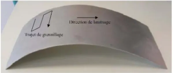
remain within the mechanical part after it has been deformed and all external forces have been removed. Macro residual stresses are the result of non homogeneous plastic deformation under the action of external treatment (such as induced by shot peening), non homogeneous plastic deformation during nonuniform cooling or heating, etc. Figure 1 shows an example of a metal sheet laminated and deformed by shot peening. Residual stresses can result in visible distortion of a component.
Fig. 1: example of a metal sheet laminated and deformed by shot peening
Residual stresses can play a significant role in explaining or preventing failure of a component at times. One example of residual stresses preventing failure is the shot peening of component to induce surface compressive stresses that improve the fatigue life of the component.
Shot peening is a classical surface treatment process which consists in impacting mechanical components with high velocity shots. This process is widely used in automotive industry to improve the fatigue resistance of parts by introducing compressive residual stresses under the peened surface
[5]. Shot peen-forming is a specific application of the shot peening process which consists in using the residual stresses state induced by the multiple shot impacts to bend and extend the treated sheet metal [6]. It is; therefore, very important to take into account the residual stresses (generated by manufacturing operations) during the development of the component. But today, few industrial sectors consider the residual stress parameter directly. In technical specifications, requirements are included that are often closely related to residual stress without actually naming it. For example an Almen intensity must be guaranteed in the case of shot peening, a roller-burnishing load, a machining procedure or a minimum treated thickness in the case of thermal or thermochemical treatment, and a maximum dimensioning tolerance in the case of a machined or welded part. [1]
Residual stresses are very difficult to foresee. In the case of shot peening many analytical and numerical models are proposed in the literature for predicting the geometrical distortions induced [7] [8] [9] [10] also experimental data [11] make it easier to take the residual stresses into account during the mechanical design.
Product-process interface modelling
The product-process interface model comes from the assumption that every manufacturing operation is based on a material flow called manufacturing skeleton in the following. This flow (or skeleton) (cf. Figure 2) is then defined with:
- Sections defining the initial and final surfaces through which the material is going (i.e. transversal surfaces).
- A trajectory on which the material is formed.
- An envelope surface which is generated. The link between envelopes generated in the process plan will provide manufacturing skins.
Flow trajectory Transversal initial surface Envelope surface Flow trajectory Transversal initial surface Envelope surface
Fig. 2: Material flow (i.e. manufacturing skeleton) definition for product-process interface. Based on that flow (called manufacturing skeleton) the material can be added (ex: injection), removed (ex: machining) or deformed (ex: forging, peen forming) to obtain the final part surfaces (called manufacturing skin). In the “added” and “removed” categories those surfaces are equal to the envelope surface.
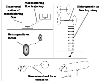
Beyond very good results presented in [12] which concern the current results of that approach for nominal aspects, figure 3 gives the novelties of that paper. The new results concern the capabilities of that product-process interface:
- To manage product tolerances coming from manufacturing operations. Each level of tolerancing features (dimensional tolerances, form tolerances and roughness) is concerned. Figure 3 shows how those features are integrated in the product-process interface (i.e. manufacturing skeleton) characteristics.
- To manage material heterogeneity coming from manufacturing operations. It is also obvious that material flows (cf. above assumption) generate some gradients inside the manufactured product. Those gradients (ex: residual stresses) can, for instance, come from:
o Thermal phenomena in the skeleton’s sections that come from a cooling phase which is not always homogeneous during casting operations.
o Mechanical deformation on the skeleton’s trajectory coming from forming processes (ex: forging, peen forming...).
Fig. 3: Example of product information issued from manufacturing process and managed by the product-process interface.
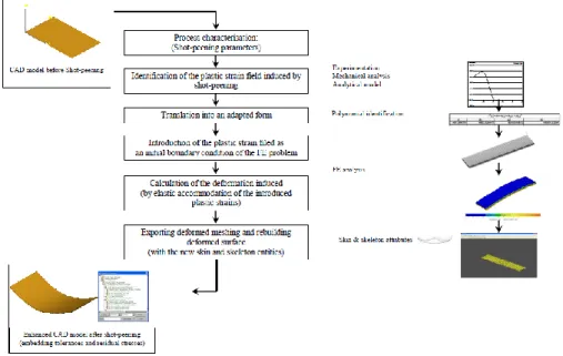
Generation of advanced CAD model taking into account residual stresses
The design tool.The generation of the enhanced CAD model is currently supported by a KBE
application that is made of
- A DFM_sythesis software that manages the product-process breakdown and the form features algorithms that generate the CAD model from manufacturing skeleton.
- A product-process database that stores information concerning manufacturing process and relations between product and process parameters. The identification is assumed, in this paper, to be already done. Three ways of identification are however treated: analytical models, experimental data, and numerical simulations.
- A Finite Elements Analysis software that is used to assess the product topology.
Integration of residual stresses: case of shot peening. The proposed solution based on the
presented product-process interface is to link residual stresses field to each manufacturing skeleton. This is represented by topological features linked to manufacturing parameters (cf. figure 4); each skeleton being adequate for each material flow of the given manufacturing operation.
The impact of material change (specifically residual stresses) based on manufacturing processes can be taken into account in the product-process interface (cf. Figure 4) and automatically processed to calculate the product deformation. The Finite Element calculation is based on an elastic analysis of the part and the solver has to reach the global equilibrium of the residual stresses in it. Since the KBE software manage the entire process plan, manufacturing expert acting as a designer can assess the product deformation with respect to each specific manufacturing operation (ex: extrusion, milling, peen forming) or to the entire process plan.
[x] x [y] : [ - 38 , 38 ] x [ -9,375 , 9,375 ] [x]spx [y]sp: [ - 38 , 38 ] x [ -9,375 , 9,375 ] e : « shell » ; [e] = [1,29] ep xx(z)= (z + 0,174)(0,0153 – 0,0753.z + 1,611.z2 ) ep yy(z)= (z + 0,174).(0,022 – 0,105.z + 1,93.z2 )
Manufa cturing skeleton « spherical
shaped » x y [x] x [y] : [ - 38 + ? x , 38 - ? x ] x [ -9,375 + ? y , 9,375 - ? y ] [x] RSx [y]RS: [ - 38 + ? x , 38 - ? x ] x [ -9,375 + ? y , 9,375 - ? y ] e : « shell » ; [e] = [1,29 - ? e] R (x , y) : « bi-plane » ; [R x] x [Ry] : [728 +/- ? Rx] x [581 +/- ? Ry] sR : « uniform » ; sR xx (z) .txt , sR yy(z) .txt
Manufacturing skin « spherical shaped »
sR (z) [x] x [y] : [ - 38 , 38 ] x [ -9,375 , 9,375 ] [x]spx [y]sp: [ - 38 , 38 ] x [ -9,375 , 9,375 ] e : « shell » ; [e] = [1,29] ep xx(z)= (z + 0,174)(0,0153 – 0,0753.z + 1,611.z2 ) ep yy(z)= (z + 0,174).(0,022 – 0,105.z + 1,93.z2 )
Manufa cturing skeleton « spherical
shaped » x y [x] x [y] : [ - 38 , 38 ] x [ -9,375 , 9,375 ] [x]spx [y]sp: [ - 38 , 38 ] x [ -9,375 , 9,375 ] e : « shell » ; [e] = [1,29] ep xx(z)= (z + 0,174)(0,0153 – 0,0753.z + 1,611.z2 ) ep yy(z)= (z + 0,174).(0,022 – 0,105.z + 1,93.z2 )
Manufa cturing skeleton « spherical
shaped » x y [x] x [y] : [ - 38 + ? x , 38 - ? x ] x [ -9,375 + ? y , 9,375 - ? y ] [x] RSx [y]RS: [ - 38 + ? x , 38 - ? x ] x [ -9,375 + ? y , 9,375 - ? y ] e : « shell » ; [e] = [1,29 - ? e] R (x , y) : « bi-plane » ; [R x] x [Ry] : [728 +/- ? Rx] x [581 +/- ? Ry] sR : « uniform » ; sR xx (z) .txt , sR yy(z) .txt
Manufacturing skin « spherical shaped »
sR (z) [x] x [y] : [ - 38 + ? x , 38 - ? x ] x [ -9,375 + ? y , 9,375 - ? y ] [x] RSx [y]RS: [ - 38 + ? x , 38 - ? x ] x [ -9,375 + ? y , 9,375 - ? y ] e : « shell » ; [e] = [1,29 - ? e] R (x , y) : « bi-plane » ; [R x] x [Ry] : [728 +/- ? Rx] x [581 +/- ? Ry] sR : « uniform » ; sR xx (z) .txt , sR yy(z) .txt
Manufacturing skin « spherical shaped »
sR (z)
Fig. 4: illustration of manufacturing skeleton of a peen forming operation to embed residual stresses information.
Product-process integration: chaining manufacturing operations
So far we have presented how product-process interface is used in a DFM approach for CAD modelling taking into account information of material heterogeneity (i.e. residual stresses - cf. figure 3) to better simulate product deformation according to the process plan.
Process simulations very often assume the initial residual stresses as null whereas it is not the industrial and physical situation. Three main scenarios have to be considered:
- To add residual stresses field on a blank part - To remove material on already-stressed part
- To add residual stresses field on an already-stressed part
The proposed product-process interface is then also interesting to “chain” every process simulation. Every simulation can indeed integrate an initial state of residual stresses with respect to the history of previous operations of the process plan (ex: stresses coming from forging, casting…).
Figure 5 illustrates how product-process interfaces with respect to former manufacturing operation are used as input information in the following simulation of the peen forming process. The simulation is currently processed with Zebulon as Finite Elements solver.
The first manufacturing operation consists in extruding material that create the parallelepiped CAD model, attached tolerances and residual stresses as previously presented. The second operation is a peen forming operation. The ball impacts all the upper face and generates plastic deformations. This simulation of the peen forming operation solves the elastic spring-back of the entire part and provides the curve part. The final residual stresses gradient is integrated in the manufacturing interface model to be used for potential further manufacturing operations as milling or drilling for instance.
Fig. 5: Illustration of transferring residual stresses embedded in skeleton from first manufacturing simulation to the next one.
Finally, once the entire manufacturing process plan is defined and the respective product information (form + residual stresses field) is generated, all this information can be exchanged with fatigue analysis software; which therefore takes into account the heterogeneity of the part to assess the global product behaviour.
Conclusion and recommendations for future work
This paper presents a product-process interface model for a DFM approach. This model based on material flow modelling with respect to skeleton and skin concepts is first used to integrate information as soon as possible in the product design. The second objective of that interface model is to manage manufacturing information linked to product characteristics (ex: residual stresses, topology, tolerances,). It is then profitable to simulate manufacturing processes taking into account the evolution of the product characteristics with respect to the manufacturing plan. The whole history of each manufacturing operation is then linked to the product definition that is not currently the case in CAD-centred design approach (or conventional CAD systems).
The main recommendations for future work are:
- The application of the KBE software to more complicated academic and industrial case studies. - The implementation of product-process relationships database that could further take into
account more manufacturing physical and technological phenomenon that are already-known; for instance vibration, or dynamic behaviours during machining operations.
- To achieve the 3 main scenarios of chaining the manufacturing operations and to treat some larger manufacturing plan: e.g. Forging + Thermal Treatment + shot peening + machining.
Acknowledgments
This research work is partly supported by SNECMA industry. It is part of the MAIA project. The experimental peen forming process has been carried out in the Sisson Lehmann (Wheelabrator group) industry.
References
[1] Lu J. “Prestress Engineering of Structural Material: A Global Design Approach to the Residual Stress Problem”, Handbook of Residual Stress Formation and Distorsion of Steel, ASM, 2002, p. 11-26.
[2] Skander A. Méthode et modèle DFM pour le choix des procédés et l’intégration des contraintes de fabrication vers l’émergence de la solution produit. Ph-D thesis, UTT, Troyes, 2006.
[3] Roucoules L., Skander A. Manufacturing process selection and integration in product design. Analysis and synthesis approaches. Proceedings of the CIRP Design seminar, Grenoble, 2003.
[4] Roucoules L., Lafon P. et al. Knowledge intensive approach towards multiple product modelling and geometry emergence to foster cooperative design. Proceedings of the CIRP Design seminar, Kananaskis, 2006.
[5] Lu J., Flavenot J.F., Lieurade H.P. Intégration des notions de contraintes résiduelles dans les bureaux d’études, démarche globale. In Les contraintes résiduelles au bureau d’études. Senlis : CETIM, 1991. ISBN 2-85400-216-0.
[6] O’Hara P. Peen-forming - A developing technique. Proceedings of the ICSP8, Garmisch-Partenkirchen 2002.
[7] Guagliano M. Relating Almen intensity to residual stresses induced by shot-peening: a numerical approach. In Journal of Materials Processing Technology. 110: 267-286, 2001.
[8] Grasty L. V., Andrew C. Shot peen forming sheet metal: finite element prediction of deformed shape. In Journal of Engineering Manufacture. 210: 361-365, 1996.
[9] Homer S. E., VanLuchene R. D. Aircaft wing skin contouring by shot-peening. In Journal of Material. Shaping Technologies. 0 (0): 2-8, 1991.
[10] Han K., Owen D. R. J. et al. Combined finite/discrete element and explicit/implicit simulations of peen forming process. In engineering computations, 19(1): 92-118, 2002.
[11] COCHENNEC F. Simulation numérique du grenaillage de mise en forme pour une intégration produit-procédés en conception mécanique ». Ph-D thesis, UTT, Troyes, 2009.
[12] Skander A, Roucoules L., Klein Meyer JS, 2008, Design and manufacturing interface modelling for manufacturing processes selection and knowledge synthesis in design. In International Journal of Advanced Manufacturing Technology, DOI 10.1007/s00170-007-1003-2, n°37, 2008.
[13] Boothroyd G., Dewhurst P. et al. Product design for manufacture and assembly. Marcel Dekker, 1994, ISBN 0- 82479-176-2.
[15] Roucoules L. Méthodes et connaissances : contribution au développement d’un environnement de conception intégrée. Ph-D thesis, INPG, Grenoble, 1999.
[16] E. Rouhaud, D. Deslaef et al. In Handbook on Residual Stress, Society for Experimental Mechanics, USA, 2005.