Science Arts & Métiers (SAM)
is an open access repository that collects the work of Arts et Métiers Institute of Technology researchers and makes it freely available over the web where possible.
This is an author-deposited version published in: https://sam.ensam.eu
Handle ID: .http://hdl.handle.net/10985/8968
To cite this version :
Zhibin ZHOU, Franck SCUILLER, Jean-Frederic CHARPENTIER, Mohamed BENBOUZID, Tianhao TANG - Power Control of a Nonpitchable PMSG-Based Marine Current Turbine at Overrated Current Speed With Flux-Weakening Strategy - IEEE JOURNAL OF OCEANIC ENGINEERING n°99, p.1-10 - 2014
Any correspondence concerning this service should be sent to the repository Administrator : archiveouverte@ensam.eu
Power Control of a Non-Pitchable PMSG-Based
Marine Current Turbine at Over-rated Current
Speed with Flux-Weakening Strategy
Zhibin Zhou, Student Member, IEEE, Franck Scuiller, Member, IEEE, Jean Frédéric Charpentier, Member, IEEE, Mohamed Benbouzid, Senior Member, IEEE, and Tianhao Tang, Senior Member, IEEE
Abstract—This paper deals with power control strategies for a fixed-pitch direct drive marine
current turbine (MCT) when the marine current velocity exceeds the rated value corresponding to the MCT nominal power. At over-rated marine current speed, the MCT control strategy is supposed to be changed from maximum power point tracking (MPPT) stage to constant power stage. In this paper, flux-weakening strategy is investigated to realize appropriate power control strategies at high marine current speeds. During flux-weakening operations, the generator can be controlled to produce nominal or over-nominal power for a specific speed range (constant power range). These two power control modes are compared and the constant power range is calculated in this paper. The relationship between the expected constant power range and generator parameters requirement (stator inductance, permanent magnet flux, nominal power coefficient) is analyzed in this paper. A Torque-based control with a robust feedback flux-weakening strategy is then carried out in the simulation. The proposed control strategies are tested in both high tidal speed and swell wave cases; the results validate the analysis and show the feasibility of the proposed control method.
Index Terms—Marine current turbine, fixed-pitch, PMSG, flux-weakening, high marine
current speed.
NOMENCLATURE
CAP = Constant active power; CPSR = Constant power speed ratio; MAP = Maximum active power; MCT = Marine current turbine;
MPPT = Maximum power point tracking; MTPA = Maximum torque per ampere;
PMSG = Permanent-magnet synchronous generator; TSR = Tip speed ratio;
HS, Tp = Swell significant height and peak period;
Cp = Power coefficient;
fB = Friction coefficient;
id, iq = Generator d- and q-axis currents;
Imax = Maximum phase current magnitude;
J = Total system inertia; KT = Generator torque constant;
Ld, Lq = Generator d- and q-axis inductances;
np = Pole pair number;
PN = Turbine nominal power;
R = Turbine blade radius; Rs = Generator stator resistance;
Te, Tm = Generator and turbine torque;
V = Marine current speed;
Vs = Generator phase voltage magnitude;
Vdc = DC-bus voltage;
Vmax = Maximum phase voltage magnitude;
vd, vq = Generator d- and q-axis voltages;
λ = Turbine tip speed ratio; ρ = Sea water density;
φ = Generator power factor angle; ψm = Permanent magnet flux;
ωe, ωeb = Electrical angle and base speeds;
ωm = Mechanical angle speed;
ωmN = Rotor nominal angle speed.
I. INTRODUCTION
Due to high predictability of the marine tides and high power potential of marine tidal currents, various marine current turbine (MCT) technologies have been developed to capture tidal current energy in recent years [1-2]. However, difficulties of underwater accessibility make compact structure and low
maintenance highly expected for MCTs. Several industrial MCT projects such as the OpenHydro (tested by French utility company EDF), Hydro Beluga 9 (Alstom) and Voith Hydro turbine system adopt non-pitchable turbine blades and use permanent magnet synchronous generators (PMSG). Two advantages of these projects can be noticed: fixed blades enable simplifying the turbine system (avoiding pitch-variable mechanism); and PMSGs enable realizing direct-drive systems (eliminating gearbox).
However, the MCT rated power would not be designed for the peak marine current speed due to the fact that the peak current speed may appear only at large spring tides and corresponds only to a small part of the statistical resource [3]. When the marine current speed is higher than the rated value, a fixed-pitch MCT is unable to limit the extracted power via fixed-pitch control as in large wind turbines [4] and some pitchable MCT turbines [5]. Therefore, an appropriate generator-side control strategy should be applied to control and limit the MCT output power.
Based on the turbine power characteristic, one possible solution is to operate the turbine at over-nominal speed during high marine current speed periods for reducing turbine power coefficient and the harnessed power. However, over-nominal speed operation leads to high electromotive force (EMF) in PM machines and may cause saturations in the generator regulators. Although various flux-weakening control strategies have been studied to realize over-base speed operations for PM machines [6-15], the flux-weakening operation mode for PMSG in renewable energy systems is still a new topic. The joint operating characteristics of the MCT and the PMSG are focused in this paper. In a previous work [16], the authors proposed to apply flux-weakening strategy for limiting the MCT power to its nominal power at high current speeds. However, the maximal generator output power during the flux-weakening operation and the impacts of generator parameters on the MCT operation range are not discussed. In this paper, these issues will be focused. Figure 1 shows the general system scheme, and the generator-side control will be focused in this paper.
In Section II, the turbine power characteristic and the generator model are presented. In Section III, the flux-weakening operation and the generator parameters impacts on the MCT operational zone are discussed. In Section IV, the proposed robust power control scheme is presented and the simulation results of the two power control modes at high marine current speed are compared. And the conclusion is then given in Section V.
Fig. 1. General scheme of a PMSG-based direct drive MCT system.
II. MARINE CURRENT TURBINE AND GENERATOR MODELS
A. Marine Current Turbine Model
The power harnessed by a horizontal-axis MCT can be calculated as
2 3
1 ρ π 2 p
P C R V (1)
The turbine power coefficient Cp depends on the turbine blade structure and hydrodynamics. For typical
MCTs, the optimal Cp value for normal operation is estimated to be in the range of 0.35-0.5 [3]. For a
given turbine and based on the experimental results, the Cp curve can be approximated as a function of
the tip speed ratio (λ=mR V/ ) and the pitch angle [17]. In this paper the considered system is a non-pitchable MCT, therefore the Cp is supposed to depend only on .
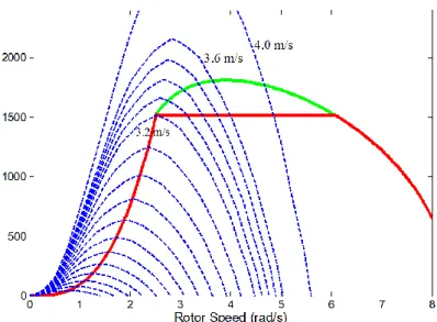
Figure 2 shows the Cp curve used in this paper, which is referenced from [18-19]. The maximum Cp
value is 0.45 which corresponds to a tip speed ratio of 6.3. This value is considered as the optimal tip speed ratio for realizing maximum power point tracking (MPPT) under the rated marine current speed. One 1.52 MW turbine is studied in this paper. The turbine maximum speed to follow MPPT is 24 rpm (2.52 rad/s) corresponding to a marine current of 3.2 m/s. When the marine current exceeds 3.2 m/s, the extracted power will be limited by operating the rotor speed over 2.52 rad/s as illustrated in Fig. 3.
B. Marine Current Generator Model
Surface-mounted PMSG (non-salient machine) is considered in this paper. Although salient PM machines can have wider flux-weakening range, non-salient PM machines are usually easier to
manufacture and are capable of achieve a smoother electromagnetic torque [20]. The PMSG model in the d-q frame is described by the equations (2).
Fig. 2. MCT Cp curve.
Fig. 3. The MCT power characteristic under different current speeds.
s s B d d ω dt ω ω ψ dt 3 ψ 2 dω ω dt d d d d e q q q q q q e d d e m e p m q m m e m i v R i L L i i v R i L L i T n i J T T f (2)
III. FLUX-WEAKENING FOR THE PMSG IN A MCT SYSTEM
A. Generator Operating Characteristics
In the synchronous rotation frame, the stator current is decomposed into a flux component id and a
torque component iq; and the following voltage and current limits should be guaranteed at any time.
2 2 2 d q max v v V (3) 2 2 2 d q max i i I (4)
Vmax is limited by the available DC-bus voltage Vdc and the converter modulation method. 1 / 3
max dc
V V for the sinusoidal wave model (linear space vector modulation) and Vmax 2 /Vdcfor the full six-step operation [10]. Imax is determined by machine torque and converter power ratings. For a
surface-mounted PM machine, the inductances in d-q axes are almost equal (Ld = Lq = Ls). By
neglecting stator resistance, the voltage limitation (3) in steady-state can then be expressed by
2 2 2 s s ψm max q d e V i i L L (5)
From (5), the voltage and current constrains can be drawn as circles shown in Fig. 4. The solid-line circle indicates the current limitation and the dotted-lines circles indicate voltage constraints which have a centre of (0, -ψm/Ls) and shrink with increased operating speeds.
The generator parameters are set to match the turbine characteristics: the generator nominal speed is set at the maximum turbine speed to realize the MPPT stage (24 rpm, 2.52 rad/s); the generator nominal active power is designed as the same value of the turbine nominal one (1.52 MW); the generator maximum torque is required at the base speed to obtain the nominal power as given by
ω ω eb N eN mN T max p P T K I n (6) where KT (3 / 2)npψm
It should be noted that if the generator maximum torque is set to a smaller value that will be required by the MPPT strategy below the nominal speed (this also means a smaller current rating of Imax), the
weakening operation range will be reduced; while a larger torque rating can result in a wider flux-weakening operation range but the generator weight and cost will be increased [29-30]. The typical control strategy for a non-salient PM machine under the base speed is to set id = 0 for maximizing the
torque per ampere ratio. When rotor speed is over the machine base speed, the voltage limitation circle will then shrink to the left side of the q-axis (as shown in Fig. 4). It indicates that negative d-axis current should be injected to decrease the total flux in the machine windings and to keep the operating points within the voltage and current limitation circles at flux-weakening operations.
Finite constant power speed ratio machine (ψm > LsImax) is considered in this paper. The maximum
torque in the flux-weakening operation is obtained when the machine operates at the intersection points of the voltage and current limitation circles. The intersection point (point A in Fig. 4) can be calculated when the equality sign is used in (4) and (5); and the corresponding id and the iq can be obtained as
follows. 2 2 2 s s s ψ 2ψ ω max m d max m e L V i I L L (7)
2 2
qmax max d
i I i (8)
If the generator output power is supposed to be limited to the nominal power at over-base speed operation (ωe > ωeb), the q-axis current reference should be calculated by
N ω (ω / ) ω eb q max qmax T T e p e T P i I i K K n (9) Figure 4 shows that for a given iq reference under iqmax, there exists a range for setting id reference
values (shown as the C-D line segment). It is not obvious to determine the optimal id reference due to
various optimization criteria. The copper loss is proportional to the square value of stator current, while the iron loss is approximately proportional to the square value of local flux density for a given speed [21-22]. So the point D corresponds to the lowest copper losses while the point C corresponds to the lowest iron losses. If the maximum torque per ampere (MTPA) strategy is applied, then the point D will be chosen as the operating point for the given iq reference.
Figure 5 illustrates the generator power characteristics in this paper. Under the base speed, the generator is supposed to operate in MPPT mode enabling the turbine to capture maximum energy from marine currents. Over the base speed, a demagnetizing current (negative id current) is injected and the
generator will operate in the flux weakening range. At the flux weakening stage, there exists a constant power range during which the generator power can be either over the nominal power with iqmax or
limited to the nominal power with iq given by (9). The id current curve in Fig. 5 is calculated by (7); the
two different iq current trajectories correspond to the coordinates described by points A and B in Fig. 4
when the rotor speed increases. However, when the rotor speed exceeds the constant power range, iq
will be limited to iqmax and the operating points of the two power control modes are the same. Over the
constant power range, the generator power will decrease rapidly below the nominal value with the increase of the rotor speed.
The flux-weakening range and constant power range depend on machine parameters. The maximum speed for the flux-weakening range can be obtained from Fig. 4 as
ω ψ max emax m s max V L I (10)
Fig. 5. Generator operating characteristics (corresponding to the Appendix data).
The flux-weakening range and constant power range depend on machine parameters. The maximum speed for the flux-weakening range can be obtained from Fig. 4 as
ω ψ max emax m s max V L I (10) The maximum speed for the constant power range can be calculated based on (7)~(9) with the equality sign in (9),
2 ω ω 1 2 eb econ pu x (11)where xpuωebL Is max/Vmax, and the parameter relationship at the base speed conforms to
2
2ω ψ ω
max eb m eb s max
V L I (12)
Then, the flux-weakening range and the constant power range can be described by the ratio of their maximum operational speeds with the base speed as follows
ω _ = ω ω ψ emax max eb eb m s max V Ratio fx L I (13)
2 ω 1 _ = ω 1 2 econ eb pu Ratio con x (14)In this paper, the generator (parameters illustrated in the Appendix) is able to have a flux-weakening range of Ratio_fx = 3.3 and constant power range of Ratio_con = 2.4 as shown in Fig. 5. This constant power range is sufficient for the generator to cope with the MCT and achieve both over-nominal power and nominal power modes during high marine current speeds. In the following, we will use the maximum active power (MAP) mode and the constant active power (CAP) mode to distinguish the two generator power control modes at the flux-weakening stage.
B. Impacts of Generator Parameters on the MCT Operation
It can be seen from Fig. 5 that both MAP and CAP modes are effective in the constant power range, while for a rotor speed over this range the generator output power will decrease rapidly below the nominal value. Therefore, it is important to study the requirements of the generator parameters for an expected constant power range. In this section, generator base speed ωeb, nominal torque TeN and the
maximum stator voltage Vmax are fixed and we therefore focus on the parameter requirements of stator
inductance and rotor permanent magnet flux. Figure 6 shows that the generator nominal power angle φ, defined at the base speed, is decided by the ratio between LsImax and ψm with the MTPA strategy.
From (13) and (14), it can be seen that the flux-weakening and constant power ranges strongly depend on LsImax and ψm. For an expected constant power speed ratio (CPSR), the required minimum
values for LsImax and Ls can be calculated as follows.
_ 1 ( ) ω 2 _ max s max eb V Ratio con L I Ratio con (15)
2 2 * 3 ( ) ω 3 ψ ( ) 2 2 max p s max s max eb p m s s max eN eN V n L I L I n L L I T T (16)Figure 7 shows the calculation results; the (LsImax)* and Ls* values in this figure are normalized by
LsImax and Ls (in the Appendix) respectively to illustrate the parameter change requirements according to
Fig. 7. Parameters corresponding to required CPSR.
different CPSRs. From (16) and Fig. 7, it can be seen that a wider CPSR requires smaller ψm and higher
Ls and Imax; these results are consistent with the studies in [31]. Although interior PM machines are
easier to realize wider flux-weakening range with their saliency, surface-mounted PM machines can also have wider flux-weakening range via proper machine design. For example, additional leakage inductance can be obtained by introducing additional cores enclosing end-windings, thus realizing a wider CPSR [32]. The generator parameters used in this paper enable the machine to have a CPSR of 2.4 with a nominal power factor of 0.84. A higher CPSR requires large stator inductance and LsImax
values thus reducing the nominal power factor. For example, stator inductance value should increase by 8.3% to obtain a CPSR of 5 but the resulted nominal power factor will be reduced to 0.77. Smaller stator inductance can improve the generator nominal power factor and then reduce the V-I rating of the
generator-side converter, however the CPSR will also be decreased and the system operable area will be limited.
For example if the inductance is designed with 1.0 mH (16.7 % smaller than Ls used in this paper),
the PMSG will have a nominal power factor of 0.9, but with a small CPSR of 1.6. Figure 8 shows the generator operating points with CPSR=1.6. The dotted-lines illustrate the turbine powers characteristics. In this case, both MAP and CAP modes can be applied when the marine current speed is between 3.2 m/s and 3.6 m/s. However, the MCT system can not produce power at a current speed of 4.0 m/s due to small CPSR and low flux-weakening capability of the generator.
Figure 9 shows the case with generator parameters chosen in this paper. It can be seen that with CPSR = 2.4, the generator enables the MCT system to produce power for a wide range of over-rated marine current speeds. At a high current speed of 4.0 m/s, the MCT system is still able to produce 1.77 MW under the MAP mode or 1.52 MW under the CAP mode.
It should be noticed that the flux-weakening operation is on the decreasing slope of the Cp (λ > λopt)
curve to reduce the turbine power coefficient during over-rated current speeds. Therefore, the turbine Cp
characteristic can also influence the expected generator CPSR for non-pitchable MCTs. The Cp curve
used in this paper has a common shape for three-blade turbines [18-19], [26]. Increasing turbine blade number could have sharper Cp and better stall performance at high current speeds. However, flatter Cp
can be found in two-blade turbines or when the blade chord and twist distribution is designed to keep high Cp values for a wide TSR range [27-28]. In this case, it would require large CPSR for the generator
to cope with the turbine at over-rated marine current speed.
Fig. 9. Generator power characteristics with CPSR = 2.4.
IV. SYSTEM SIMULATION AT HIGH MARINE CURRENT SPEED
A. Robust MCT Power Control Strategy
From (7) it can be seen that the model-based d-axis current reference requires accurate information about machine parameters and operating speed. Actually, robust flux-weakening methods are more favorable in real applications to overcome the parameter indeterminacy and variations. The flux-weakening method proposed in [13-14] is chosen in this paper for its robustness and high utilization of the DC-bus voltage. Figure 10 illustrates the generator-side control scheme with the flux-weakening algorithm for the MCT. The difference between the current controller output (voltage reference) and the converter output voltage is used to generate the id reference. The low-pass filter (LPF) is used to reject
voltage signals high-frequency components.
The torque-based MPPT strategy is applied when the generator speed is under the nominal value. This torque-based MPPT calculates the reference generator torque as a function of Cpmax, λopt and ωm.
When the rotor speed is gradually driven by the high marine current speed to be over the nominal speed, the generator will be accelerated to over-base speed operation points with the flux-weakening algorithm. The reference torque can be calculated by the constant power requirement. Equation (17) illustrates the torque control reference used in this paper.
Fig. 10. Generator-side control scheme with flux-weakening strategy. 5 2 3 if ω ω if ω > ω ω 1 ρπ ω 2 λ m m pmax m op N m mN m t N C R T P (17)
The MTPA strategy is embodied in this control scheme. Indeed, id* is generated to maintain the
operating points on the voltage constraints. Therefore, this control scheme is able to achieve the maximum active power (MAP) mode as at point A (in Fig. 4) and the constant active power (CAP) mode with minimum copper losses at point D (in Fig. 4). For the CAP mode, iq* is calculated from the
torque reference (second equation in (17)) to keep the generator output power at its nominal value; and for the MAP mode, iq* is set to
2 2
max d
I i for maximizing the generator torque and output power.
B. Under High Tidal Speed
The MCT is supposed to be installed at a proper depth under the sea-surface so that normal sea waves generated by local winds will have negligible influence on the MCT system. High speed marine currents would occur at large spring tides or under strong sea states (caused by swell waves or storms). In this section, the sea is supposed to be calm (without significant swell waves) and the high marine current speed driven by spring tides are considered.
Fig. 11. Tidal speed in the Raz de Sein for one month [3].
Figure 11 gives an example of tidal current speed in the Raz de Sein (potential site for MCT project off the coast of Brittany, France) during one month based on tidal current data from SHOM (French Navy Hydrographic and Oceanographic Service). It can be seen that the peak tidal speed can reach 3.6 m/s for this site at spring tides. Without power limitation control, the maximum extractable power at the peak tidal speed would be over 2 MW for the MCT.
In the simulation of this section, the marine current speed is set initially at 2.8 m/s and then rises to 3.6 m/s during 20 s to 70 s as shown in Fig. 12. After 47 s, the current speed rises over the rated value (3.2 m/s) and the power control mode with flux-weakening strategy will be applied. Although this current speed rising process is not very realistic (the tidal speed changes very slowly in reality because a tidal cycle may correspond to approximately half a day), it enables to test and compare the proposed control strategies at high spring tides. The turbine speed response, generator torque, generator output power, and generator losses under the MAP (green line) and CAP (red line) modes are illustrated from Figs. 13 to 17. The steady-state results at 3.6 m/s are then summarized in Table 1.
Fig. 13. Rotor speed responses at high tidal speed.
Fig. 14. Generator torque responses at high tidal speed.
It can be seen that when the tidal current speed rises to the rated value of 3.2 m/s at about 47 s (Fig. 12), the MCT rotor speed will reach the nominal value of 24 rpm (Fig. 13) and the generator torque will reach its maximum value about 600 kNm (Fig. 14). When the current speed rises over the rated value, the flux-weakening strategy will be triggered and the rotor speed will rise over the nominal speed. Both MAP and CAP modes are simulated. Figure 13 and 14 show that at over-rated marine current speeds, the CAP mode features lower generator torque to accelerate the turbine to a higher speed than the MAP mode. The reason is that the CAP mode requires reducing the turbine Cp value more than the MAP
mode in order to keep the generator output power at the nominal value for a given over-rated current speed. While MAP mode aims to generate maximum torque and then maximize the generator output power as shown in Fig.14 and Fig. 15.
Fig. 16. Copper losses of the generator.
Table 1. Steady-State Performance at Current Speed of 3.6 m/s. Control mode Rotor speed (rpm) Electromagnetic torque (kNm) Electromagnetic power (MW) Copper losses (kW) Iron losses (kW) MAP 34.5 505 1.82 21 7.8 CAP 38 381 1.52 14.8 7.3
The generator copper losses (Joule losses) are calculated by
2 2
copper s
3 2 d q
P i i R (18)
The specific iron losses (W/kg) can be calculated based on the following common relationship.
0 0 0 a b Fe Fe Fe Fe B f P P B f (19)
where BFe and f are respectively the flux density and the field frequency in the stator iron core, and PFe0
represents the iron losses per mass at the given frequency f0 and the flux densityBFe0. The typical value
of a and b can be set as 2.2 and 1.5, respectively [24]. In a simplified approach, the fundamental harmonic of the flux density BFe can be considered to be proportional to Vs/f and (19) can then be
rewritten as 2.2 0.7 0 0 0 s Fe Fe V f P P V f (20) In this paper, the typical point for calculating the iron losses is chosen at the base point (V0 = Vmax and f0
= ωeb/2π ) and the corresponding PFe0 is 2.5 W/kg. The total iron mass in the stator core of the 1.5 MW
generator is estimated to be about 4 tons [22]. The iron losses calculation results under both CAP and MAP modes are shown in Fig. 17.
As analyzed in the previous section, the MAP mode operates on the intersection points of voltage-current limitation circles and maintains the stator voltage-current at its maximum magnitude Imax, while the CAP
mode operates at a smaller stator current. The results from Fig. 16 confirm that the generator copper losses are kept at the maximum value by the MAP mode, and the CAP mode enables to greatly reduce the copper losses at over-rated marine currents. The iron losses difference is not very big because both modes operate at Vmax with the MTPA strategy during the flux weakening operation. The iron losses
under MAP mode are a little higher than under CAP mode. This indicates that CAP mode reduces more flux density in the stator core.
From the simulation results and Table 1, it can be seen that at steady-state with a marine current speed of 3.6 m/s, the MAP mode will accelerate the turbine to 1.45 times of the nominal speed and produce 19.7% power more than the nominal value; while the CAP mode will accelerate the turbine to 1.58 times of the nominal speed and limit the generator power to the nominal power of 1.52 MW. Compared to the MAP mode, the generator copper losses are reduced by 29.5% and the iron losses are reduced by 6.4% with the CAP mode at steady-state under a marine current speed of 3.6m/s.
C. Under Swell Effect
Swell refers to long-length ocean waves (usually over 150 m) generated by distant storms [25]. Long distance dispersion makes the swell energy more accumulated than local wind-generated waves. Swells can propagate very deep below the sea surface and therefore have a non-negligible effect on the MCT system. Indeed, swell effect can lead to marine current speed fluctuations on a period of about 10 to 20 s. In this paper, a medium-strong sea state with significant wave height Hs = 3 m and typical wave
period Tp = 13.2 s is considered (it corresponds to typical sea state in the winter off the western coast of
Europe). Details of the swell modeling can be found in [23]. The total marine current speed is calculated as the sum of tidal current speed and swell-induced current speed variations. It should be noticed that the tidal current speed can be considered as a constant during a short-time period due to tidal phenomenon. Figure 18 shows the marine current speed under swell effect: it can be seen that even the tidal current speed is fixed at 2.8 m/s, the total marine current speed will exceed the rated value of 3.2 m/s during some short periods caused by the swell-induced current variations.
Figures 19 and 20 show the rotor speed and generator power responses in MAP and CAP modes respectively. It should be noticed that under swell effect, the marine current speed is fluctuating and there is no steady-state for the turbine. The turbine will not be accelerated to the same operating points as in steady-state cases, but the CAP mode will still accelerate the rotor speed a little higher than in the MAP mode to limit the generator power to its nominal value. In this case, the MAP can produce about
4% power more than the CAP mode during the main flux-weakening stages (40-45 s, 78-83 s and 93-98 s) as shown in Fig. 20.
Fig. 18. Marine current speed under swell effect.
Fig. 19. Rotor speed responses under swell effect.
Fig. 21. Generator stator currents in the d-q axis.
Fig. 22. Torque responses under swell effect (CAP mode).
Figure 21 compares the d-q currents with the MAP and CAP modes under swell effect. Lower iq (and
generator torque) can be noticed in the CAP mode than in the MAP mode. The difference of d-axis currents is very small because the CAP mode operates at a little higher speed than the MAP mode. In this case, the CAP mode has about 8% less copper losses than the MAP during the main flux-weakening stages. Figure 22 shows the turbine and generator torques under the CAP mode and this points out that for a large MCT system (with large total inertia), a big difference between the turbine and generator torques is required to accelerate or decelerate the system in dynamic stages.
This paper has investigated power control strategies for a PMSG-based MCT with non-pitchable blades at over-rated current speed. Flux-weakening control strategy has been proposed to accelerate the turbine and generator system over the nominal speed for power limitation control at high marine current speed. Two power control modes (the maximum active power mode and the constant active power mode) on the generator constant power range have been investigated. In this context, a torque control scheme with a robust flux-weakening algorithm has been applied. High speed marine currents caused by high tidal current speed and swell effect have been both considered.
The achieved simulation results have confirmed that at over-rated current speed, the constant active power mode enables to limit the generator output power to the nominal value with lower losses while the maximum active power mode enables to produce over-nominal power (better use the generator-side converter V-I rating) but with high copper losses. The parameter requirements of the non-salient PM machine for expected constant power speed ratio are provided in this paper. The compromise between high power factor and large constant power range should be noticed for appropriate generator parameter design.
APPENDIX
TABLE 2. SYSTEM PARAMETER LIST
Sea water density 1027 kg/m3 Turbine blade radius 8 m
System total inertia 1.3131×10⁶ kg.m2 Maximum Cp value 0.45
Optimal TSR for MPPT 6.3 Rated marine current speed 3.2 m/s
MCT nominal power 1.52 MW Generator nominal phase voltage 649 V (RMS) Generator nominal phase current 928 A (RMS)
DC-bus voltage 1500 V Rotor nominal speed 24 rpm
Pole pair number 125
Permanent magnet flux 2.458 Wb Generator stator resistance 0.0081Ω Generator d-q axis inductance 1.2 mH
REFERENCES
[1] A.S. Bahaj, “Generating electricity from the oceans,” Renewable and Sustainable Energy Review, vol. 15, n°7, pp.3399-3416, Sept. 2011.
[2] S. Benelghali, M.E.H. Benbouzid and J. F. Charpentier, “Marine tidal current electric power generation technology: State of the art and current status,” in Proceedings of the 2007 IEEE IEMDC, Antalya (Turkey), vol. 2, pp. 1407-1412, May 2007.
[3] S. Benelghali, R. Balme, K. Le Saux, M.E.H. Benbouzid, J.F. Charpentier and F. Hauville, “A simulation model for the evaluation of the electrical power potential harnessed by a marine current turbine,” IEEE Journal on
Oceanic Engineering, vol. 32, n°4, pp. 786-797, Oct. 2007.
[4] H. Polinder, “Overview of and trends in wind turbine generator systems,” in Proceedings of the 2011 IEEE
Power and Energy Society General Meeting, San Diego (USA), pp. 1-8, Jul. 2011.
[5] T. Thiringer, J. MacEnri, and M. Reed, “Flicker evaluation of the SeaGen tidal power plant,” IEEE Trans.
Sustainable Energy, vol. 2, n°4, pp. 414-422, Oct. 2011.
[6] S. Morimoto, M. Sanada, and Y. Takeda, “Effects and compensation of magnetic saturation in flux-weakening controlled permanent magnet synchronous motor drives,” IEEE Trans. Industry Applications, vol. 30, n°6, pp. 1632-1637, Nov./Dec. 1994.
[7] D. Lu, and N. C. Kar, “A review of flux-weakening control in permanent magnet synchronous machines,” in
Proceedings of the 2010 IEEE VPPC, Lille (France), pp. 1-6, Sept. 2010.
[8] M. Tursini, E. Chiricozzi and R. Petrella, “Feedforward flux-weakening control of surface-mounted permanent-magnet synchronous motors accounting for resistive voltage drop,” IEEE Trans. Industrial Electronics, vol. 57, n°1, pp. 440-448, Jan. 2010.
[9] J. H. Song, J. M. Kim, and S. K. Sul, “A new robust SPMSM control to parameter variations in flux weakening region,” in Proceedings of the 1996 IEEE IECON, Taipei (China), vol. 2, pp. 1193–1198, Aug. 1996.
[10] D. S. Maric, S. Hiti, C. C. Stancu, J. M. Nagashima, and D. B. Rutledge “Two flux weakening schemes for surface-mounted permanent-magnet synchronous drives - Design and transient response considerations”, in
Proceedings of the 1999 IEEE ISIE, Bled (Slovenia), vol. 2, pp. 673-678, Jul. 1999.
[11] H. Liu, Z. Q. Zhu, E. Mohamed, Y. Fu and X. Qi, “Comparison of drive performance of PM synchronous machine fed by inverters with different PWM strategies in constant torque and constant power regions,” in
Proceedings of the 2011 IEEE IEMDC, Niagara Falls (Canada), pp. 1334-1339, May 2011.
[12] P.Y. Lin, and Y. S. Lai, “Voltage control technique for the extension of dc-link voltage utilization of finite-speed SPMSM drives,” IEEE Trans. Industrial Electronics, vol. 59, n°9, pp.3392-3402, Sept. 2012.
[13] T. S. Kwon, and S. K. Sul, “Novel antiwindup of a current regulator of a surface-mounted permanent-magnet motor for flux-weakening control,” IEEE Trans. Industry Applications, vol. 42, n°5, pp.1293-1300, Sep./Oct. 2006.
[14] T. S. Kwon, and S. K. Sul, “A novel flux weakening algorithm for surface mounted permanent magnet synchronous machines with infinite constant power speed ratio,” in Proceedings of the 2007 IEEE ICEMS, Seoul (Korea), pp. 440-445, Oct. 2007.
[15] H. Liu, Z. Q. Zhu, E. Mohamed, Y. Fu, and X. Qi, “Flux-weakening control of nonsalient pole PMSM having large winding inductance, accounting for resistive voltage drop and inverter nonlinearities ,” IEEE Trans. Power
Electronics, vol. 27, n°2, pp.942-952, Feb. 2012.
[16] Z. Zhou, F. Scuiller, J.F. Charpentier, M.E.H. Benbouzid and T. Tang, “Power limitation control for a PMSG-based marine current turbine at high tidal speed and strong sea state,” in Proceedings of the 2013 IEEE IEMDC, Chicago (USA), pp.75-80, May 2013.
[17] J.G. Slootweg, S.W.H. de Haan, H. Polinder and W.L. Kling, “General model for representing variable speed wind turbines in power system dynamics simulations,” IEEE Trans. Power Systems, vol. 18, n°1, pp.144-151, February 2003.
[18] L. Myers and A. S. Bahaj, “Power output performance characteristics of a horizontal axis marine current turbine,” Renewable Energy, vol. 31, n°2, pp.197–208, Feb. 2006.
[19] W. M. J. Batten, A. S. Bahaj, A. F. Molland, and J. R. Chaplin, “The prediction of the hydrodynamic performance of marine current turbines,” Renewable Energy, vol. 33, n°5, pp.1085-1096, May 2008.
[20] S. Chaithongsuk, B. Nahid-Mobarakeh, J.P. Caron, N. Takorabet, and F. Meibody-Tabar, “Optimal design of permanent magnet motors to improve field-weakening performances in variable speed drives,” IEEE Trans.
Industrial Electronics, vol. 59, n°6, pp. 2484-2494, Jun. 2012.
[21] J. Aubry, H. B. Ahmed, B. Multon, “Sizing optimization methodology of a surface permanent magnet machine-converter system over a torque-speed operating profile: application to a wave energy machine-converter,” IEEE Trans.
Industrial Electronics, vol. 59, n°5, pp. 2116-2125, May 2012.
[22] H. Li, Z. Chen, H. Polinder, “Optimization of multibrid permanent-magnet wind generator systems,” IEEE Trans.
Energy Conversion, vol. 24, n°1, pp. 82-92, Mar. 2009.
[23] Z. Zhou, F. Scuiller, J.F. Charpentier, M.E.H. Benbouzid and T. Tang, “Power smoothing control in a grid-connected marine current turbine system for compensating swell effect,” IEEE Trans. Sustainable Energy, vol. 4, n°3, pp. 816-826, Jul. 2013.
[24] L. Drouen, J.F. Charpentier, E. Semail, and S. Clenet, “Study of an innovative electrical machine fitted to marine current turbine,” in Proceedings of the 2007 IEEE OCEANS, Aberdeen (UK), pp. 1-6, Jun. 2007.
[25] Y. Goda, Random Seas and Design of Maritime Structures. Advanced Series on Ocean Engineering, vol.33, World Scientific: Singapore, 2010.
[26] A. M. Eltamaly, “Modeling of wind turbine driving permanent magnet generator with maximum power point tracking system,” J. King Saud Univ., vol. 19, Eng. Sci. (2), pp. 223-237, 2007.
[27] D. P. Coiro, F. Scherillo, R. Familio, U. Maisto and G. Troise, “Experimental test campaign on an innovative device to harness clean energy from tidal and river current,” in Proceedings of the 2009 IEEE ICCEP, Capri (Italy), pp. 87-92, Jun. 2009.
[28] F. Scherillo, U. Maisto, G. Troise, D. P. Coiro and S. Miranda, “Numerical and experimental analysis of a shrouded hydroturbine,” in Proceedings of the 2011 IEEE ICCEP, Ischia (Italy), pp. 216-222, Jun. 2011.
[29] R.H. Moncada, R.A. Rodriguez, J.A. Tapia, and T.M. Jahns, “Axial flux permanent-magnet machine under optimum control strategy for wind power generation,” in Proceedings of the 2009 IEEE IEMDC, Miami (USA), pp. 1065-1071, May 2009.
[30] M. Morandin, E. Fornasiero, S. Bolognani, and N. Bianchi, “Torque and power rating of a wind-power PM generator drive for maximum profit-to-cost ratio,” IEEE Trans. Industrial Applications, vol. 49, n°2, pp.866-872, Mar./Apr. 2013.
[31] N. Bianchi and S. Bolognani, “Parameters and volt-ampere ratings of a synchronous motor drive for flux-weakening applications,” IEEE Trans. Power Electronics, vol. 12, no5, pp.895-903, Sep. 1997.
[32] T.S. Kwon, S.K. Sul, L. Alberti, and N. Bianchi, “Design and control of an axial-flux machine for a wide flux-weakening operation region,” IEEE Trans. Industrial Applications, vol. 45, n°4, pp.1258-1266, Jul./Aug. 2009.
Zhibin Zhou (M’13) was born in Shanghai, China, in 1983. He received the B.Sc. degree in electrical engineering in 2006 from Shanghai Maritime University, Shanghai, China, the M.Sc. degree in electronics system in 2008 from Polytech’Nantes, Saint-Nazaire, France, a second M.Sc. degree in power electronics and electric drive in 2009 from Shanghai Maritime University, China.
Currently he is working toward Ph.D. degree in Electrical Engineering in the University of Brest and in the French Naval Academy, Brest, France. His current research interests include modeling and control of marine renewable energy systems, power electronics and energy storage systems.
Franck Scuiller (M’11) was born in Brest, France, in 1977. He received the electrical engineer degree (M.Sc. degree) from ENSIEG, INPG (Grenoble National Polytechnic Institute) in 2001 and the Ph.D. degree from “Arts et Métiers ParisTech” in 2006.
In 2007, he worked as a lecturer in French Naval Academy. From 2008 to 2011, he was a technical project manager in warship electric power system for French DCNS Company. Since September 2011, he has been an Associate Professor in the French Naval Academy in Brest, France. His research interesting include marine current turbine and ship propulsion with multi-phase machine, ship grid modeling and simulation, new grid topologies for improving the electrical energy availability and quality.
Jean Frédéric Charpentier (M’02) was born in Tananarive, Madagascar, in 1969. He received the M.Sc. and PhD degrees in electrical engineering from the National Polytechnic Institute of Toulouse, Toulouse, France in 1993 and 1996 respectively. From 1996 to 1997 he was a post doctoral fellow at Laval University, Québec, Canada. From 1997 to 2002 he was an Assistant
Professor at the Institut Universitaire de Technologie of Brest, University of Brest, Brest, France. Since 2002, he has been an Associate Professor in the French Naval Academy in Brest, France. His current research interests include design aspects on electrical machines and drives, electrical naval propulsion systems and marine renewable energy.
Mohamed El Hachemi Benbouzid was born in Batna, Algeria, in 1968. He received the B.Sc. degree in electrical engineering from the University of Batna, Batna, Algeria, in 1990, the M.Sc. and Ph.D. degrees in electrical and computer engineering from the National Polytechnic Institute of Grenoble, Grenoble, France, in 1991 and 1994, respectively, and the Habilitation à Diriger des Recherches degree from the University of Picardie “Jules Verne,” Amiens, France, in 2000.
After receiving the Ph.D. degree, he joined the Professional Institute of Amiens, University of Picardie “Jules Verne,” where he was an Associate Professor of electrical and computer engineering. Since September 2004, he has been with the Institut Universitaire de Technologie of Brest, University of Brest, Brest, France, where he is a Professor of electrical engineering. His main research interests and experience include analysis, design, and control of electric machines, variable-speed drives for traction, propulsion, and renewable energy applications, and fault diagnosis of electric machines. Prof. Benbouzid is an IEEE Senior Member. He is an Associate Editor of the IEEE TRANSACTIONS ON ENERGY CONVERSION, the IEEE TRANSACTIONS ON INDUSTRIAL ELECTRONICS, the IEEE TRANSACTIONS ON SUSTAINABLE ENERGY, and the IEEE TRANSACTIONS ON VEHICULAR TECHNOLOGY. He was an Associate Editor of the IEEE/ASMETRANSACTIONS ON MECHATRONICS from 2006 to 2009.
Tianhao Tang (SM’01) was born in Jiangsu, China, in 1955. He received the B.Sc. and the M.Sc. degrees in electrical engineering from the Shanghai University of Technology, Shanghai, China, in 1982 and 1987 respectively, the Ph.D. degree in control engineering from the Shanghai University, Shanghai, China in 1998.
From 1988 to 1991 he was a Lecturer at the Shanghai Maritime University Shanghai, China, where he became an Associate Professor and a Professor in 1992 and 1998 respectively. He is currently the Director of the Department of Electric Drives and Control Systems in the Shanghai Maritime University, Shanghai, China, and the vice-Director of the Sino-French Joint Research Institute of Galileo & Maritime ITS for Safer Seas. His main research interests are intelligent control, electrical propulsion systems and power electronics in renewable applications.
![Figure 2 shows the C p curve used in this paper, which is referenced from [18-19]. The maximum C p](https://thumb-eu.123doks.com/thumbv2/123doknet/7314761.210289/5.892.197.699.113.272/figure-shows-c-curve-used-paper-referenced-maximum.webp)


![Fig. 11. Tidal speed in the Raz de Sein for one month [3].](https://thumb-eu.123doks.com/thumbv2/123doknet/7314761.210289/16.892.241.655.104.355/fig-tidal-speed-raz-sein-month.webp)
