HAL Id: hal-00472314
https://hal.archives-ouvertes.fr/hal-00472314
Submitted on 21 Apr 2021HAL is a multi-disciplinary open access archive for the deposit and dissemination of sci-entific research documents, whether they are pub-lished or not. The documents may come from teaching and research institutions in France or
L’archive ouverte pluridisciplinaire HAL, est destinée au dépôt et à la diffusion de documents scientifiques de niveau recherche, publiés ou non, émanant des établissements d’enseignement et de recherche français ou étrangers, des laboratoires
Effect of depth etching on Bragg reflectors realized by
focused ion beam in Ti:LiNbO3 waveguide
K. Ghoumid, R. Ferriere, Badr-Eddine Benkelfat, G. Ulliac, R. Salut, J.-Y.
Rauch, T. Gharbi
To cite this version:
K. Ghoumid, R. Ferriere, Badr-Eddine Benkelfat, G. Ulliac, R. Salut, et al.. Effect of depth etching on Bragg reflectors realized by focused ion beam in Ti:LiNbO3 waveguide. Photonics North 2009, May 2009, Quebec, Canada. pp.738613, �10.1117/12.839692�. �hal-00472314�
Effect of depth etching on Bragg reflectors realized by
Focused Ion Beam in Ti:LiNbO3 waveguide
K. GHOUMID
1, R. FERRIERE
1, B.-E BENKELFAT
2, G.ULLIAC
1,
R. SALUT
1,J.-Y. RAUCH
1and T. GHARBI
11
Femto-St Département d'optique P.M. Duffieux -UMR 6174, Université de Franche-Comte,
16 route de Gray, 25030 Besançon Cedex (France).
2
Institut TELECOM, Telecom & Management Sud-Paris; Samovar UMR CNRS 5157;
9 rue Charles Fourier, 91011 Evry Cedex (France).
email : kamal.ghoumid@univ-fcomte.fr
ABSTRACT
In this paper we have studied effect of depth etching on the Bragg gratings (BGs) realized by Focused Ions Beam. This technique has the advantage to induce a direct waveguide structuring without intermediate media, comparing to traditional methods. A reflectivity of 96% within a window centred at 1550 nm is obtained. The effect of the depth etching on the transmittance and the bandwidth at half maximum is demonstrated.
Keywords: Bragg grating, Lithium niobate, Transmittance, Focused Ions Beam.
1. INTRODUCTION
A Bragg grating is a periodic or aperiodic perturbation of the effective refractive index in the waveguide or in the core of an optical fiber. This leads to the reflection of light in a narrow/wide range of wavelengths, for which a Bragg condition is satisfied. This basically means that the wavenumber of the grating matches the difference of the wavenumbers of the incident and reflected waves, In other words, the complex amplitudes corresponding to reflected field contributions from different parts of the grating are all in phase so that can add up constructively; this is a kind of phase matching. Other wavelengths are nearly not affected by the BG.
The reflection bandwidth of a BG depends on the length, the depth and the strength of the refractive index modulation. The narrowest bandwidth values, as are desirable e.g. for the construction of single-frequency fiber lasers or for certain optical filters, are obtained for long gratings with weak index modulation. Large bandwidths may be achieved with short and strong gratings, but also with aperiodic designs. One of the key parameters to increase the reflectivity is the depth of modulation index.
Bragg grating inscription is commonly used in integrated optics applications for the realization of wavelength-dependent resonators, distributed Bragg reflectors (DBR) and fiber lasers [1], and there continues to be significant interest in studying convenient and reproducible fabrication technologies. Fabrication methods are usually based on the photorefractive [2], effect and dry etching [3], and ultraviolet (UV) induced surface-relief gratings on LiNbO3 channel waveguides have also been reported [4, 5], a photorefractive-index difference induced by femtosecond laser pulses has been employed to realize gratings in oxides [6].
In this paper, we propose an efficacy method for the design of BGs in a Ti-indiffused waveguide by Focused Ions Beam [7, 8]. Because of the sputtering capability, the FIB is used as a micro-machining tool, to modify or machine materials at the micro- and nanoscale, FIB micro machining has become a broad field of its own. The milling of samples using FIB is different from the other "traditional" techniques involving lithography and subsequent etching. The essential difference comes from the fact that it uses a direct etching without other additional technological steps. The ion beam processing on a solid target induces a significant transformation of its structure and its physical properties.
Thus, using this technique, we study the effect of the depth etching of corrugation on the reflectivity and bandwidth.
2. THEORY AND SIMULATIONS
Fig. 1 shows the basic structure considered, consisting of a waveguide of index n2 indiffused in a substrate of index n1 and the whole structure is embedded in air with index n3 = 1. A grating is formed as a result of periodic index modulations
Δ
n
=
n
2−
n
3. The substrate index is n1 = 2.2121, and the grating period isΛ
(L = N.Λ
is length of BG, where N is number of periods).Fig 1: Basic scheme of a Bragg grating etched in a Ti:LiNbO3
With index modulation given above and according to the principle of a BG, the reflected wavelength (λB), called the Bragg wavelength, is defined by the following relation
λ
=
Λ
Where neff is the effective index of the propagating mode, m the Bragg order,
Λ
andλ
B are defined before. Ifκ
is the coupling coefficient that quantifies the strength of the grating,Λ
−
=
Δ
π
λ
π
β
2
is the mismatching parameter, whereλ
π
β
=
2
is the propagation constant of the waveguide,λ
is wavelength, and the decouplingδ
=
κ
2−
Δ
β
2 , then the spectral response of the reflection coefficient and its bandwidth at half maximumΔ
λ
given respectively by following equations [9]:( )
( )
( )
( )
L
sh
j
L
ch
L
sh
δ
β
δ
δ
δ
κ
λ
Δ
+
=
ℜ
(2) 2 2.
1
.
⎟
⎠
⎞
⎜
⎝
⎛
−
=
Δ
π
κ
λ
λ
L
L
n
eff (3) The transmittance is defined byT
(
λ
)
=
1
−
R
(
λ
)
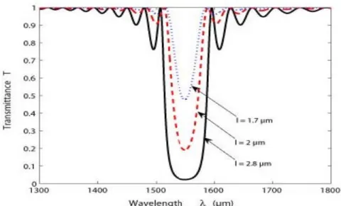
(losses are neglected)Any increase in the depth l of the modulation index, an increased coupling coefficient
κ
, therefore an increase in reflectivityℜ
(T decrease), and the bandwidth at half maximumΔ
λ
.The curves of simulation of the transmittance versus wavelength for various values etching depth are given in figure 2. In these simulations, neff = 2.2184, m = 5 (fifth order) and
Λ
=
1
.
8
µm
.These curves show the relationship between the etching depth, the reflectivity and bandwidth; if l increases, then
ℜ
andλ
Δ
also increase (T decrease).3. FABRICATION PROCESS AND RESULTS
The single-mode optical waveguides in the 1550 nm window were fabricated by standard indiffusion of 80 nm thick and 7 μm wide titanium layers at 1020°C during 10 h, on a sample of lithium niobate of type X-cut, Z-propagation and TM polarization. The next step, is etching BG. The ion beam processing on a solid target induces a significant transformation of its structure and its physical properties. However, for a sufficient amount of ions, it produces a sputtering of the target material. For the experiments, we use a dual beam Orsay Physics Canion 31 / LEO 4400 FIB, the command of the beam deflection is realized by a Raith Elphy Quantum 4.0 driver. The current and ions energy values used for the LiNbO3 sputtering are respectively 300 pA and 30 keV.
We get then a BG one whose parameters are: period Λ = 1.8 μm, m = 5, N = 80, it is given in Figure 3.
Fig 3: Bragg grating etched in TiLiNbO3 waveguide
The experimental setup for visualization of the transmittance is given in Figure 4. It consists of a continuous spectrum source in the wavelength range of {850 – 1750} nm; focusing lenses; P is a Glan polarizer to selectively probe TM mode and an optical spectrum analyser (OSA).
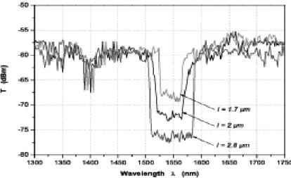
Experimental results of the transmittance and the bandwidth versus wavelength for various etching depths are given in figures 5, and compared to the reference curve for which l = 0. We can see that the reflectivity increases with the etching depth, indeed reflectivity greater than 70%, 90% and 96% are achieved for l = 1.7 μm, 2 μm and 2.8 μm respectively. At the same time, the bandwidth at half maximum Dn decreases from 60 to 28 nm.
The realization of the BG based on Ti:LiNbO3 optical waveguide has been demonstrated and the experimental results confirm well the theoretical results.
Fig 4: Measurement setup to characterize Bragg grating transmittance.
Fig 5: Transmittance versus wavelength for various etching depths.
4. CONCLUSION
We have demonstrated that using a FIB to etch Bragg gratings in a titanium-diffused optical waveguide in lithium niobate allows to achieve very high reflectance ($96\%$). We have studied the influence of the depth etching l on the transmittance and the bandwidth at half maximum. Thus, any increase in the depth of the index modulation, leads to a decrease in transmittance and increased bandwidth at half maximum.
This method of machining lithium niobate opened the voice on several applications.
REFERENCES
[1] A. Yariv, M. Nakamura " Periodic structure for integrated optics", IEEE-JQE vol 13 4 pp 233-251 (1977).
[2] B.K. Das, R.Ricken, W. Sohler, "Integrated optical distributed feedback laser with Ti:Fe:LiNbO3 waveguide", Appl.Phys. Lett vol 82, 10, pp 1515-1517 (2003).
[3] J. Söchtig, "Ti:LiNbO3 stripe waveguide Bragg reflector gratings", Electron. Lett., vol. 24, no. 14, pp. 844-845,(1988).
[4] B. Wu, P. L. Chu, H. Hu, and Z. Xiong, "UV-induced surface-relief gratings on LiNbO3 channel waveguides", IEEE J. Quantum Electron., vol. 35, pp. 1369-1373 (1999).
[5] Y. Sidorin and A. Cheng, "Integration of Bragg gratings on LiNbO3 channel waveguides using laser ablation", Electron. Lett., vol. 17, no. 5, pp. 312-314 (2001).
[6] N. Takeshima, Y. Kuroiwa, Y. Narita, S. Tanaka, K. Hirao, "Fabrication of a periodic structure wit a high refractive-index difference by femtosecond laser pulses", Optics Express, vol 14, n°17 pp 4019-4021 (2004).
[7] K. Chaganti, I. Salakhutdinov, I. Avrutsky, G.-W. Auner, and J. Mansfield, "Sub-micron grating fabrication on hafnium oxide thin-film waveguides with focused ion beam milling", Opt. Express, vol 14, pp 1505-1511 (2006).
[8] F. Lacour, N. Courjal, M.-P. Bernal, A. Sabac, C. Bainier, and M. Spajer, "Nanostructuring lithium niobate substrates by focused ion beam milling", Opt. Materials, vol 27, pp 1421–1425 (2005).
[9] B.-E. Benkelfat, R. Ferriere, B. Wacogne, and P. Mollier, "Technological Implementation of Bragg Grating reflectors in Ti:LiNbO3 Waveguides by Proton Exchange", IEEE Photonics Technology Letters, vol 14, pp 1430-1432 (2002).