HAL Id: hal-00492786
https://hal.univ-brest.fr/hal-00492786
Submitted on 17 Jun 2010HAL is a multi-disciplinary open access archive for the deposit and dissemination of sci-entific research documents, whether they are pub-lished or not. The documents may come from teaching and research institutions in France or abroad, or from public or private research centers.
L’archive ouverte pluridisciplinaire HAL, est destinée au dépôt et à la diffusion de documents scientifiques de niveau recherche, publiés ou non, émanant des établissements d’enseignement et de recherche français ou étrangers, des laboratoires publics ou privés.
On-Chip Interconnects
Yves Quéré, Thierry Le Gouguec, Pierre-Marie Martin, Denis Le Berre,
Fabrice Huret
To cite this version:
Yves Quéré, Thierry Le Gouguec, Pierre-Marie Martin, Denis Le Berre, Fabrice Huret. Simulation, Measurement and Modeling of Orthogonal On-Chip Interconnects. 15th Topical Meeting on Electrical Performance of Electronic Packaging, EPEP, Oct 2006, Scottsdale, United States. pp.153-156. �hal-00492786�
Simulation, Measurement and Modeling of Orthogonal On-Chip
Interconnects
Yves Quere, Thierry Le Gouguec, Pierre-Marie Martin, Denis Le Berre,and Fabrice Huret
LEST-UMR CNRS n°6165-CS 93837-29238 BrestCedex 3-France
Phone: +33 (0)2-98-01-82-73; Fax: +33(0)2-98-01-63-95; Email:
yves.quereOuniv-brest.fr
Abstract - This paper explains the appearance of resonant frequency due to underlayer orthogonal metal grid in microstrip line structures. Inthe contextof global interconnects, this resonant frequency may lead to noise and has to be estimate. A model, which allowsone toapproximate thisresonantfrequency, is validated bymeasurement.
I.INTRODUCTION
Afeature of evolution in Microelectronics is the marked enhancement of integration- andcircuits-running speeds.A trend in modernhigh speed CMOS VLSIcircuits is the reduction of features sizes togetherwith the increase ofchip dimensions. Today, the race towards integration is slowed down by the problem of global interconnects, which constitutes one of the blocking points in the improvement of circuits performances. Further to the elevation of operating frequencies inhigh-speed digital circuits, propagation delaysare affectedby couplingnoise [1]-[2].
In CMOS technology circuits, the transistors are connected by copper lines at various metal levels. Generally, all the copper conductorsplaced on a samelevel areparallel,whereas the lines are orthogonally built on the closer level. On-chip high-speed interconnects with underlayer orthogonal metal grids, including grid-backed lines (GBLs) and grid-backed coplanar waveguide(GBCPWs), have been studied in recent papers [3]-[8]. Asignificantenhancement of transmission characteristics due to the presence ofunderlayer orthogonal metal grid have been demonstrated in the case of GBLs [7]-[8] and a weaker effect has been observed for coplanar interconnects [7]. Moreover, a resonant frequencyhas been observed in the case ofcoplanarandmicrostriplines [7].
In this paper, we explain the appearance of resonant frequency due to orthogonal metal grids in coplanar and microstrip line structures. Simulations and measurements, which illustrate these frequencies, are presented in section II. Amodel which allows one to approximatethe resonant frequencyisproposedand validated in sectionIII.
II.SIMULATIONANDEXPERIMENTAL VALIDATION
In this part, microstrip and coplanar structure with underlayer metal grid are presented. The simulation of these structures has been made with the electromagnetic solver Momentum (Agilent) in the 1-50 GHz frequency range. TRL calibration has been used for measurements. Structures with various griddensities have been realized. We study two different cases ofgrid, floating or connected to the ground. Inthis paper, we only presentthe study results of microstripline structures. A measurement result ofcoplanarlines will be illustrated in the conclusion.
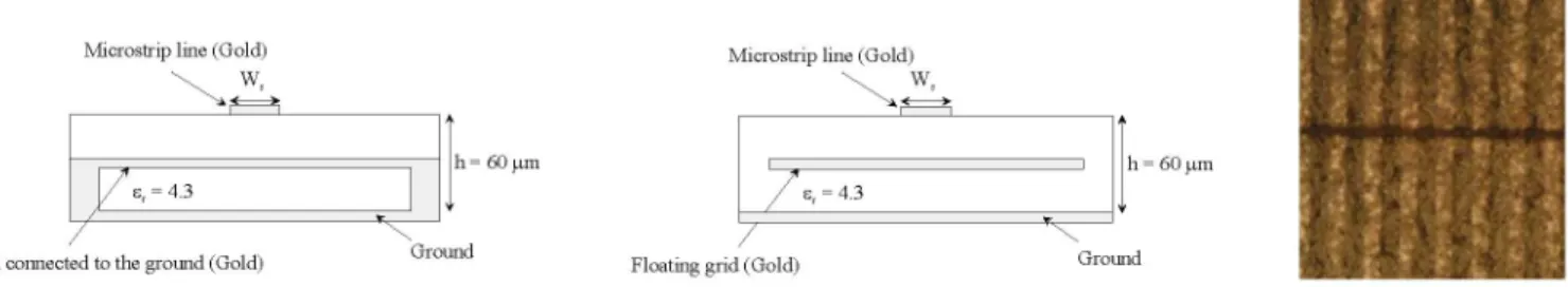
Microstripline(Gold) Microstripline(Gold)
43.K 60 tn {h 60Sun
Grid connectedtotheground (Gold) Ground Floatinggnrd(Gold)Ground
Fig. 1. Cross-section ofmicrostriplinestructurewith connectedgrid (ontheleft)andfloating grid(onthemiddle) topviewpictureof the realizedmicrostripstructure(ontheRight). (W =30tm)
C Coplanarline(Gold)
< > <--- < >
Sc Sc
h= 60 utm e =4.3
Connected g -d(Gold) Bulk(F, 9.6)
WCoplanar
line(Gold)< > <--> < >
Sc Sc
, h=60utm t gi 4.3B
Floating grid (Gold) Bulk(F, 9.6)
Fig. 2. Cross-section of coplanar line structure with connected grid (on the left) andfloating grid (on themiddle);topviewpicture of the realized coplanar structure (on the Right).(W,=30tm, W,=170tm,S=70tm)
The line length is equal to 1.5 mm, the thickness of metallization is equal to 4
prm
and the grid is placed on the middle of the substrate. Thegrid linelengthisequalto 3.285 mmwhen the spacingand width vary in the 50-100 pim range. In the presented results, grid line width and space are equal to 50prm.
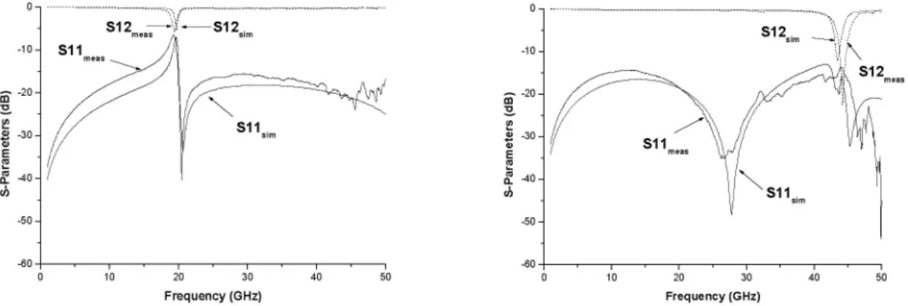
The simulated and measured S-parameters, inthe case ofmicrostrip lines with connected andfloatingunderlayermetalgrid, arepresentedinfigure3. We note agoodagreementbetween simulations and measures and the presence, in each cases of a resonantfrequency. Inthe case of connected grid,the resonantfrequency is equalto 20 GHz,andequalto 45 GHzinthe case offloating grid. The set of measures and simulations shows that the resonant frequency value is weakly dependent on grid density, number ofgrid line and space between grid andmicrostrip line. The resonant frequency especially depends on gridlines length, substrate relativepermittivity andgridlines termination.0-S12 > - S12. S11 meas X Sim SIImeas~ S1im 10 20 30 Frequency(GHz) -10-- -20 -a 0 30-E 4-5 -40 -U) -50 -40 50 10 20 30 Frequency(GHz)
Fig.3. Simulated and measuredS-parametersformicrostriplinestructurewith connectedgrid (ontheleft)andfloating grid (ontheright). The S-parameters evolution and the two different values of the resonant frequency (in the case of connected or
floating grid) areindications that the structurecould becomparedtoastub filter usedinmicrowavedomain, naturally
connectedby acapacitance. Inthecase of stubfilters, theresonantfrequency of short-circuit stub is twicelargerthan an open-circuit one. The underlayermetal gridbehavior is then oppositetothe stub one. Inthenextsection, wewill
model the metal grid by comparison withthe stub in ordertofind theresonantfrequencyvalue.
III.MODELINGANDTHEORETICAL VALIDATION
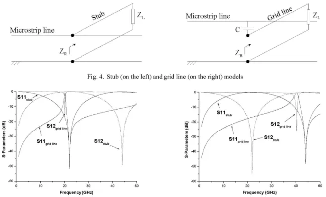
Figure 4presents themicrostrip structure model withaconnected stub and with anunderlayer metal line. ZR is the
stub or grid line input impedance, ZL the termination impedance and C the capacitance between the grid and the
microstrip line. Circuit simulations, using geometricvalues of the structure, show (Fig. 5)that considering only one
grid line permits to find the measured resonant frequency in the both cases, connected and floating grid line.
Moreover, a comparison between the simulatedS-parameters of the model with stub and the grid line one show an
oppositebehavior. Indeed,theresonantfrequency ofaparallel short-circuit stub(Fig. 4) is closedtothe floating grid one.Reciprocally, theresonantfrequencyofaparallel open-circuitstub is closedtoaconnectedgridline one.
154 0- -10-s-20 - 20--30 -E o -40 --50 -S12sim S12..as S11
\S1i
40 50 l6 -60ZL Microstrip line
Microstrin line
ZR /
Fig.4. Stub (on theleft) andgrid line (on the right)models
0- -10-a-20 -m 30-E L -40 --0) -50 0-
-10-Slgrid line SI2stub
a -20-a 0 -30 -E L -40 -U) -50 -0 1F020 30 Frequency(GHz) I gridline 0 10 S12gridline S12 40 50 Frequency(GHz)
Fig. 5. Simulated S-parameters withstuborunderlayer grid line terminated by short-circuit (on the left) and open-circuit (on the right).
Input stub impedance calculation permits to obtain theresonant frequency fR ofa stub. Input stub impedances and
associated resonant frequencies are given in equations (1)-(2) and (3)-(4) for short- and open-circuit termination
respectively. The input stub impedance is called ZR, ZC is the stub characteristic impedance, ,6 the phase factor, Ithe
stublength, creff the effectiverelative permittivity of the substrate andcthe lightvelocity. (1) ZR =
jZ'tg(/81)
2 (2) JR = ,_ ;_ 2/ 8re,ff (3)Z =~R2jtg(/81)
(4)fR
In the case of perpendicular grid line, the input impedance ZR has to be added to the capacitance C. This new
impedance is called
Zp
in equations (5) and (6) where equation (5) corresponds to a connected grid structure andequation (6)afloatingone.
Z ZR+ ct(8)
(5) 2 = _ + c R jZctg(/)
jCw 2
Zc
+ZRtg(/8l)
(6)Z =j(2
] +Theresonantfrequencyappearswhen the impedance
Zp
isequaltozero, iewhen relations (7)and(8)arerespected.(7) =arctg( )
zCc (8) /3/ =arctg(- C2 )
The capacitance C is, generally, very weak (near to 20 fF in our case of concern). Then, it is possible to
approximate in afirst order the resonant frequency fR by equation (9) for a connected grid and equation (10) for a
floatingone.
ZL
cZ
ZR
These resonant frequencies depend on the grid line length and on the effective relative permittivity. In deed, any
decrease in effective relative permittivity and grid line length involves an increase in resonant frequency value.
Consequently, the noise caused by underlayer orthogonal metal grid is reduced.
(9)
jR
=41
(10) R21/
IV. CONCLUSION
In this paper, we evidenced by simulation andmeasurement, in the case of microstrip line, aresonant frequency due
to orthogonal metal layer. We showed that this resonant frequency can be easily approximate and we demonstrated
that connected grid involves in a resonant frequency twice weakly than a floating grid. Moreover, the resonant
frequency value especially depends onthe length of orthogonal lines and on the relative permittivity of the substrate.
Its also depends on the capacity between the grid and the microstrip or coplanar lines, but its effect is weaker dueto
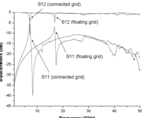
its low value. We also measured the S-parameters ofa coplanar structure with an underlayer orthogonal metal grid
(Fig. 6). These measures also show the appearance ofresonant frequencies due to this orthogonal layer, but which
appears at lower frequencies due to a different equivalent model. The later has been also found and permits to approximatetheresonant frequency ofa coplanar linestructure.
A work prospect is the evaluation of the resonant frequency influence on the transmission of high-speed digital
signals. S12(connected grid) 0 m 5 S12(floating grid) 100 -15-20 Sl 1i(floatinggrid) E 25 C 30
-51l1
(connected grid) Ch -35- -40--45 I 10 20 30 40 50 Frequency(GHz)Fig. 6. MeasuredS-parameterswithunderlayer orthogonalmetalgridconnected andfloatingfor thecoplanarstructure.
REFERENCES
[1] A. Deutsch, P. W. Coteus, andG. V. Kopscay, "On-chipwiring design challenges for gigahertz operation,"Proc. IEEE,vol. 89,no. 4,pp.
529-555,Apr. 2001.
[2]S. Morton, "On-chipinductance issues in multiconductorsystems," Proc. DesignAutomationConference, pp. 921-926, Jun. 1999.
[3] Y.
Quere,
T. Le Gouguec, P.M. Martin, andF. Huret,"InterconnectMode Conversion In High-Speed VLSI Circuits," IEEEInternationalSymposium on QualityElectronic Design(ISQED), San Jose(USA),pp. 265-270, Mar.2004.
[4] L. David, C.
Cregut,
F. Huret, Y.Quere,
F. Nyer"ReturnPath Assumption Validation for Inductance Modeling in Digital Design" IEEEworkshopon Signal PropagationonInterconnects, May 2005.
[5] Y.
Quere,
T. Le Gouguec, P.M. Martin, D. Le Berre, F. Huret, L. David, and C. Cregut,"3-D Frequency-Dependent RLC ElementsExtraction by Full Wave Analysis Identification of the Return Current Paths in Complex Power Ground Grids of High Speed VLSI
Circuits" IEEEworkshopon Signal PropagationonInterconnects, May2005.
[6] Y.Quere,T. Le Gouguec,N.Tanguy,P.M.Martin, D. Le Berre, F. Huret,"High-Frequency Effects of OrthogonalInterconnect Layers On
Inductance in High-SpeedVLSICircuits". IEEE workshoponSignalPropagationonInterconnects, May2006.
[7] P. Wang, and E. Chich-Chuan Kan, "High-Speed Interconnects With Underlayer Orthogonal Metal Grids," IEEE Trans. on Advanced
Packaging,vol. 27,no. 3,pp.497-507, Aug. 2004.
[8] D. Lutz, V. K. Tripathi, and A. Weisshaar, "Enhanced Transmission Characteristics of On-Chip Interconnects with Othogonal Gridded
Shield," IEEETrans. On Advanced Packaging, vol. 27,no. 3,pp. 497-507, Aug.2004.